 Products Home / Motorized Stages / Motorized Vertical Stages / Linear Z-Axis Stage Driven by an Amplified Piezo Motor
Linear Z-Axis Stage Driven by an Amplified Piezo Motor
- 2 nm Resolution in Open Loop Operation
- Travel Range: 1100 µm in Open Loop; 800 µm in Closed Loop
- 300 g Load Capacity
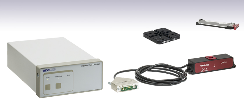
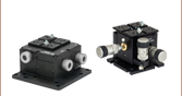
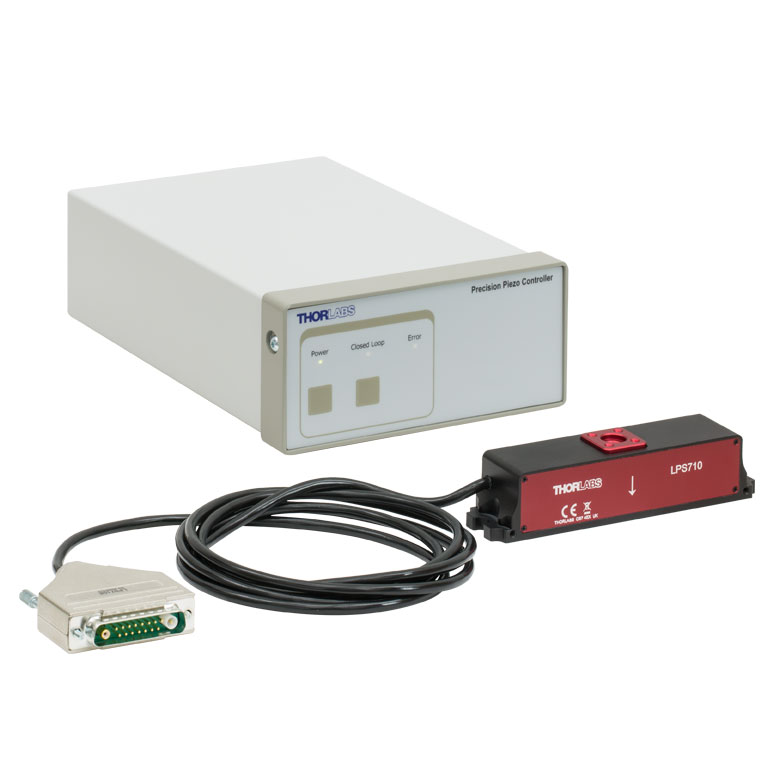
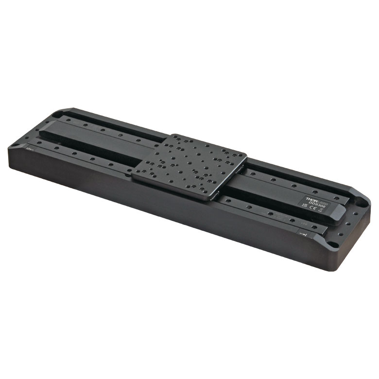
LPSA1
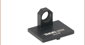
Optional Microscope Slide Holder
(Slide Not Included)
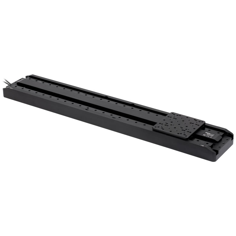
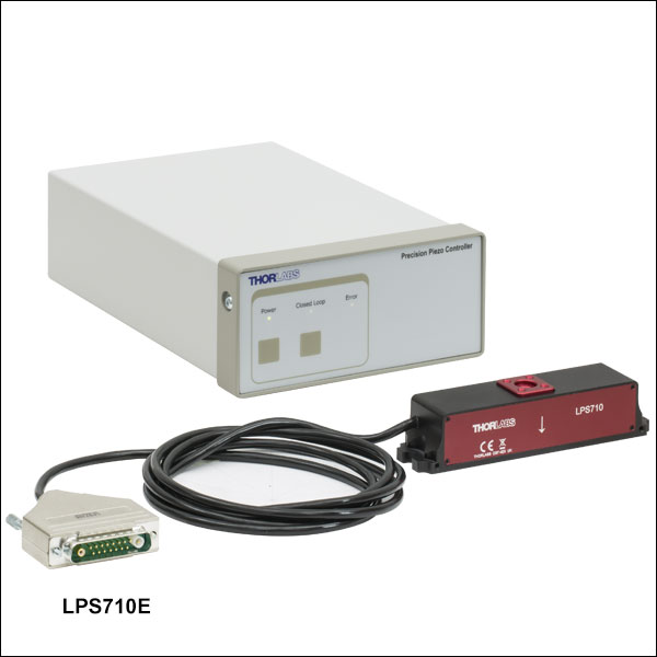
LPS710E
Linear Piezo Stage
with Included Controller
Engraved Arrow Indicates
Direction of Travel
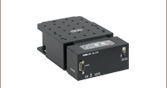
LPSA4
Optional Mounting Plate


Please Wait
| Key Specificationsa | ||
|---|---|---|
| Drive Voltage Range (Max) | -25 V to 150 V | |
| Travel | Open Loop | 1100 µm ± 10% |
| Closed Loop | 800 µm | |
| Resolution | Open Loop | 2 nm |
| Closed Loop | 6 nm | |
| Accuracy | Closed Loop | ±0.06% (Over Full Travel Range) |
| Bidirectional Repeatability | Closed Loop | ±0.03% (Over Full Travel Range) |
| Maximum Loadb | 300 g (0.66 lbs) | |
| Outer Dimensions (L x W x H) |
130 mm x 28 mm x 30 mm (5.1" x 1.1" x 1.2") |
|
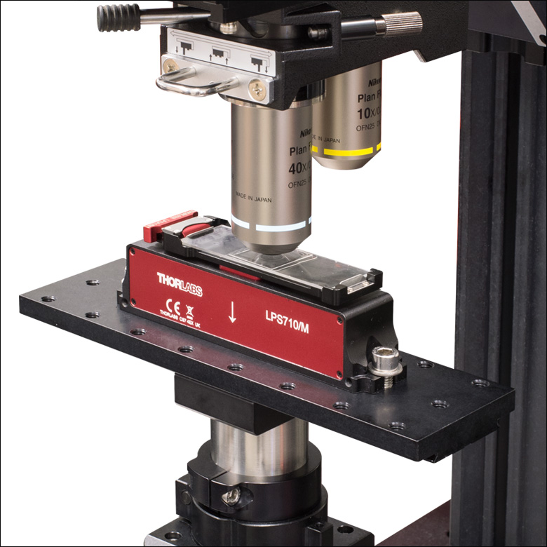
Click to Enlarge
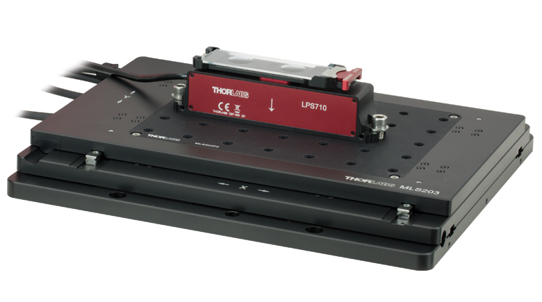
Figure 1.2 LPS710(/M) Piezo Stage with LPSA1 Slide Holder Mounted on a Rigid Stand Within a Custom Cerna® Microscope
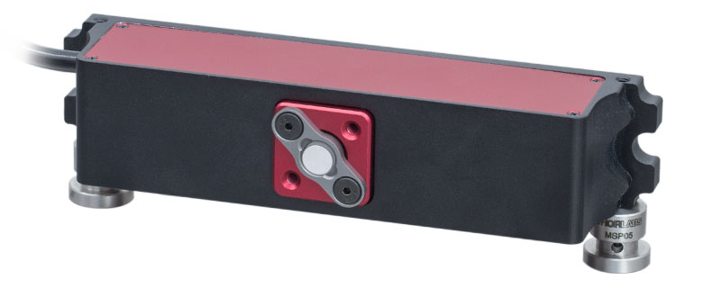
Click to Enlarge
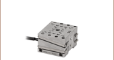
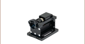
Figure 1.1 Two MSP05 Pedestal Posts Used to Horizontally Mount the LPS710 Stage and Fixed Mirror Mount Accessory
Features
- Long, Piezo-Driven Travel Range
- 1100 µm When in Open Loop
- 800 µm When in Closed Loop
- Paired, High-Precision Controller and Capacitive Feedback Sensors Provide High-Resolution Positioning
- 2 nm Resolution in Open Loop
- 6 nm Resolution in Closed Loop
- Standalone Kinesis® Interface, ThorImage®LS Integration, and Control via External Voltage
- Optional Accessories Available for Increased Versatility
- Microscope Slide Holder for Sample Positioning and Z-Stack Acquisitions
- Ø7 mm Mirror Mount for Use in Laser Cavities, Interferometers, or Spectrometers
- Mounting Plate with 3.0 mm Keyway and 8-32 (M4) and 6-32 (M3) Taps
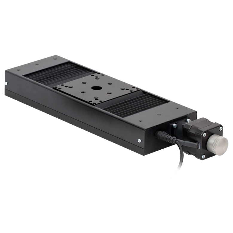
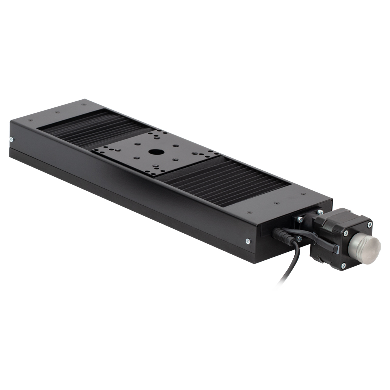
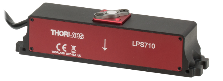
The LPS710E(/M) is a linear, Z-axis stage driven by a mechanically amplified piezo actuator with integrated capacitive position feedback sensor. It is bundled with a matched, factory-calibrated high-precision piezo controller to maximize positioning accuracy. This design is ideal for applications requiring a long, piezo-controlled travel range with submicron repeatability, nanometer positioning resolution, and fast millisecond response and settling times. This includes laser scanning microscopy, spectroscopy, or interferometry. Additionally, an optional slide holder, mirror mount, and mounting plate are available below to increase the versatility of the stage.
The stage is driven by a discrete piezo stack housed within a hardened steel flexure structure that preloads the piezo stack and amplifies its displacement by a factor of approximately 10. This leads to an overall displacement of 800 µm and 1100 µm when in operated in closed and open loop, respectively, and a maximum load capacity of 300 g (0.66 lbs). Built-in capacitive feedback sensors along with our high-precision piezo controller provide 6 nm resolution in closed-loop operation, enabling active compensation for short- and long-term drifts. When used in open loop, the controller will provide an accurate readout of the stage position with a resolution of 2 nm. An engraved arrow on the side of the unit indicates the direction of travel.
The 21.0 mm x 21.0 mm mounting surface on the top of the stage is equipped with four 4-40 (M3) blind mounting holes that are 4.8 mm deep. They can be used to mount our optional slide holder, fixed optic mount accessories, or mounting plate, all seen below, as well as other 4-40 (M3) equipped components.
The base of the stage includes two slots for 1/4"-20 (M6) cap screws and four slots for 4-40 (M3) cap screws that can be used to secure the stage to an optical table or breadboard. In addition, the stage has two bottom- and side-located 4-40 (M3) mounting holes that can be used to secure the stage using our line of mini-series components, as shown in Figure 1.1.
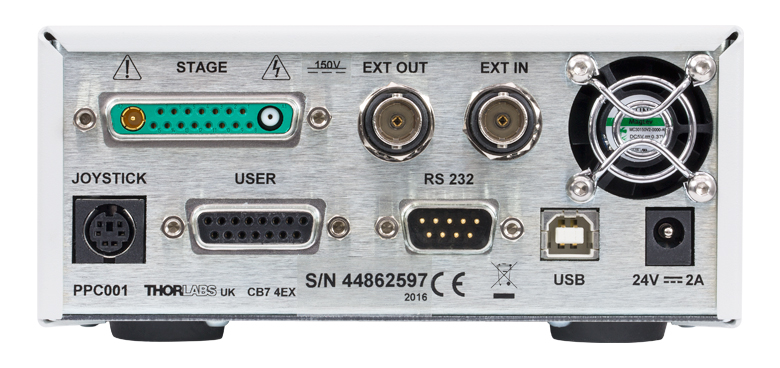
Each stage is shipped with a piezo controller that has been factory calibrated to the specific stage. Piezo control is supported through the included Kinesis GUI, our ThorImage®LS image acquisition software, or an externally supplied control voltage. See the Software & External Control tab for more details. The controller offers USB and RS-232 interfaces for computer control; a BNC input for the addition of sine, sawtooth, and square wave drive signals; and a BNC output that gives either positioning feedback from the scanner's built-in capacitive sensors or a signal proportional to the piezo drive voltage. In addition, a DB15 connector provides signals that can be used for synchronization with external equipment.
| Piezo Stage Specifications | |
|---|---|
| Open-Loop Travel Range (-25 V to 150 V) | 1100 µm ± 10% |
| Closed-Loop Travel Range | 800 µm |
| Open-Loop Resolution | 2 nm |
| Closed-Loop Resolution | 6 nm |
| Maximum Loada | 300 g (0.66 lbs) |
| Feedback Transducer Type | Capacitive |
| Resonant Frequency (15 g Load) | Primary: 185 Hz ± 15% Secondary: 115 Hz ± 15% |
| Pull Force (Increasing Voltage) | 55 N ±15% |
| Push Force (Decreasing Voltage) | 45 N ±15% |
| Accuracy (Closed Loop - Over Full Travel Range) |
±0.06% |
| Bidirectional Repeatability (Closed Loop - Over Full Travel Range) |
±0.03% |
| Angular Error (Closed Loop - Over Full Travel Range) |
±40 µrad |
| Stiffness | 0.1 N/µm ±20% |
| Capacitance | 16 µF ± 15% |
| Cable Length | 2 m (6' 7") |
| Connector | Male 15-Way Mixed Signal Combination D-Sub |
| Dimensionsb | 130 mm x 28 mm x 30 mm (5.1" x 1.1" x 1.2") |
| Dimensions (Excluding Mounting Plate) | 130 mm x 28 mm x 28.5 mm (5.1" x 1.1" x 1.12") |
| Weightc | 180 g (0.40 lbs) |
| Operating Temperature Range | 5 to 40 °C |
| Controller Specifications | ||
|---|---|---|
| Piezoelectric Output | ||
| Drive Voltage Range | -25 V to +150 V | |
| Drive Voltage Stability | 100 ppm over 24 Hours (After 30-Minute Warm-Up) |
|
| Drive Voltage Noise | <0.5 mV (RMS)a | |
| Output Current | 150 mA | |
| External Input (BNC) | ||
| Input Voltage Rangeb | -10 V to +10 V | |
| Input Voltage for Full Range | 10 V DC ± 2% | |
| Input Impedance | 10 kΩ | |
| Absolute Maximum Input Voltage | ±20 VDC | |
| External Output (BNC) | ||
| Output Voltage Range | 0 V to +10 V Nominal for Full Range (Output can Swing Negative in Certain Scenarios) |
|
| Output Impedance | 100 Ω | |
| Minimum Recommended Output Impedance | 10 kΩ | |
| Physical Specifications | ||
| Input Powerc | Input Voltage | 24 VDC ± 5% |
| Input Current | <2 A | |
| Dimensions | 205.0 mm x 147.0 mm x 68.3 mm (8.07" x 5.79" x 2.69") |
|
| Weight | 1.65 kg (3.63 lbs) | |
| Operating Temperature Range | 5 to 40 °C | |
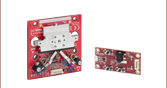
Click to Enlarge
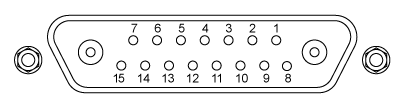
Figure 2.2 Back Panel of PPC001 Piezo Controller
Information on the connectors is available in the Pin Diagrams tab.
Click to Enlarge
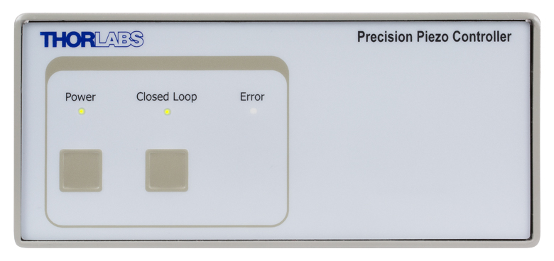
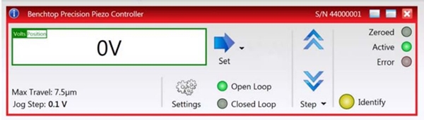
Figure 2.1 Front Panel of PPC001 Piezo Controller
In the software, the front panel LEDs can be set to three intensities: full, dim, or off. The dim mode, shown here, is the default setting.

Click to Enlarge
Click for Raw Data
The positioning accuracy of the LPS710E piezo stage is provided over a range of target positions. In this test the stage is being operated in closed loop. A target position is set and a position error is found. Both forward and backward directional movements are measured. A Renishaw XL-80 laser interferometer was used to obtain this data.

Click to Enlarge
Click for Raw Data
The displacement response of the LPS710E piezo stage to applied voltage is plotted above. In these tests, the voltage was first increased from 0 V to 150 V, then decreased to -25 V, and finally returned to 0 V. The initial and final positions are offset slightly due to hysteresis. A Renishaw XL-80 laser interferometer was used to obtain this data.
Click to Enlarge
Click for Raw Data
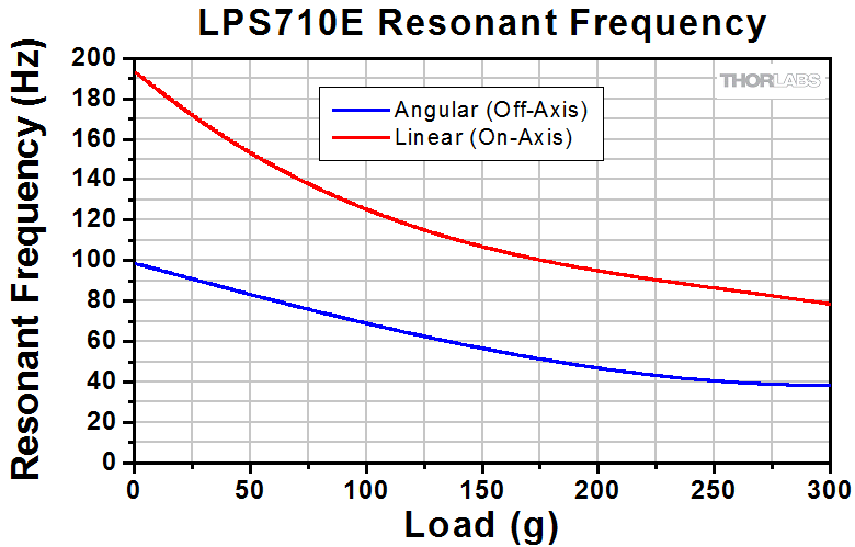
The resonant frequency of the LPS710E piezo stage as a function of the applied load is plotted above. Linear resonance occurs when the mounted load is symmetric with respect to the top mounting hole, or "on-axis". Angular resonance occurs when a load is mounted asymmetrically with respect to the top mounting hole, or "off-axis." To minimize angular resonance modes, keep the load's center of mass as close to the top mounting hole as possible.
Click to Enlarge
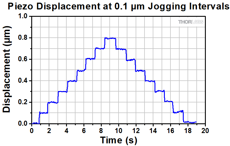
The positioning behavior of the LPS710E was measured over time. In this test the stage is set to Jog at 0.1 µm intervals. The stage is being operated in closed loop, around the mid-range of travel (400 µm), and with a 14 g load mounted. A Renishaw XL-80 laser interferometer was used to obtain this data.
Software
Kinesis Version 1.14.58
The Kinesis Software Package includes a GUI for control of the stage.
Also Available:
- Communications Protocol
![]()
Click to Enlarge
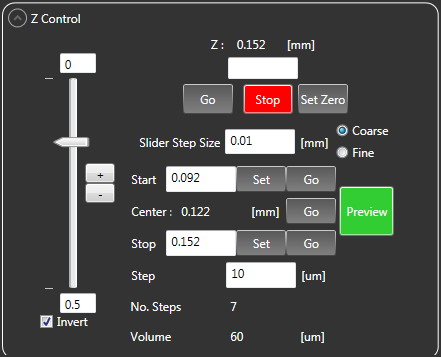
Figure 4.2 Z Control Panel from ThorImage®LS Capture Setup Tab
Click to Enlarge
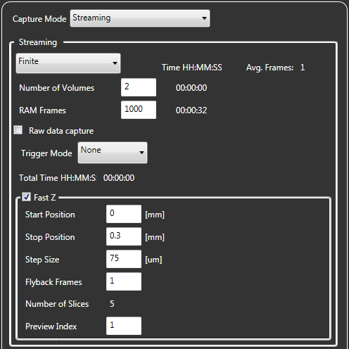
Figure 4.3 Fast Z Panel from ThorImageLS Capture Tab
The stage can be driven using the included standalone Kinesis® GUI, our ThorImage®LS software for Bergamo® III and confocal microscopes, or an externally supplied control voltage. In addition, a DB15 connector provides signals that can be used for synchronization with external equipment. Complete details on control are available in the LPS710E Kinesis manual (PDF link).
Open-Loop Operation vs. Closed-Loop Operation
There are two operating modes for positioning the stage: open loop and closed loop. In open-loop operation, which supports a travel range of 1100 µm ± 10%, the user controls the piezo drive voltage (in V). The applied drive voltage corresponds to some amount of stage displacement. For piezoelectric materials, this displacement does not depend linearly on the applied voltage: it exhibits nonlinearity and hysteresis. It is therefore not straightforward to position the stage by choosing the drive voltage. The stage's controller and built-in capacitive feedback sensors measure the stage displacement with
2 nm resolution in open-loop operation.
In closed-loop operation, which supports a travel range of 800 µm, the user directly controls the stage displacement (in µm). The built-in capacitive feedback sensors measure the stage displacement with 6 nm resolution in closed-loop operation.
Standalone Kinesis GUI
The Kinesis GUI supports both open- and closed-loop operation. The piezo drive voltage or stage displacement can be directly typed in or incremented or decremented in fixed, user-defined amounts.
In addition, the GUI enables manual PID loop tuning. The default settings are designed to provide stable operation, but manually fine tuning the PID loop and notch filters helps account for the specific objects mass in use in the experiment, reducing positional overshoots and ringing about the commanded objective position.
A screenshot is shown in Figure 4.1.
ThorImageLS Image Acquisition Software
ThorImageLS supports closed-loop operation. It allows the movement of the stage to be controlled from the same interface as Thorlabs' Bergamo II and confocal microscopes, greatly simplifying experimental integration. For convenience, controls for the stage are found in both the Capture Setup and Capture tabs. Screenshots are shown in Figures 4.2 and 4.3.
The ThorImageLS software works in conjunction with the Kinesis GUI, so the settings for the IO Control Mode should be set to 'Software + External BNC' before controlling the stage.
Externally Supplied Control Voltage
In this mode, the stage supports both open- and closed-loop operation. The voltage is applied using the external input BNC connector on the controller. The drive voltage or stage displacement that is determined by the input voltage is added to the value that is set in the GUI. If this sum would result in a drive voltage outside the -25 V to +150 V range, those limits will not be exceeded.
The external input BNC connector is typically used with sine, sawtooth, or square drive signals. The maximum frequency of the signal that should be applied depends upon the waveform. For large periodic waveforms (i.e., sine waves that provide >200 µm of total displacement), the recommended drive frequencies are:
- ≤40 Hz for Loads up to 50 g
- ≤30 Hz for Loads from 50 g to 150 g
- ≤20 Hz for Loads from 150 g to 300 g
For staircase waveforms with step sizes up to 50 µm, the minimum time between steps can be as small as the 25 ms typical settling time.
DB15 Connector
For photostimulation, electrophysiology, and optogenetics applications, the DB15 connector on the controller provides several electrical signals that can be used to synchronize the movement of the piezo stage with other equipment, such as multiphoton imaging lasers, patch clamp electrodes, and LED light sources. Details on this connector are available in Appendix A.2 of the Kinesis manual (PDF link).
Piezo Controller Pin Diagrams
Stage Connector
| Pin | Description | Pin | Description |
|---|---|---|---|
| 1 | HV Ground (Return) | 8 | HV Ground (Return) |
| 2 | Not Used | 9 | Not Used |
| 3 | Not Used | 10 | Stage IDb |
| 4 | Sine Wave Drive Output | 11 | Low Voltage Ground |
| 5 | Not Used | 12 | Low Voltage Ground |
| 6 | +15 V (Preamp Supply)a | 13 | Piezo ID (Legacy Stages)b |
| 7 | Low Voltage Ground | 14 | Position Sense Input (Strain Gauge) |
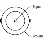
| Coaxial Male |
Position Sense Input (Capacitive) |
15 | -15 V (Preamp Supply)a |
| Coaxial Female |
HV Output |
User Connectora
Female DB15
| Pin | Description | Return | Pin | Description | Return |
|---|---|---|---|---|---|
| 1 | Digital Output 1 | 5, 9, 10 | 9 | Digital Ground | - |
| 2 | Digital Output 2 | 5, 9, 10 | 10 | Digital Ground | - |
| 3 | Digital Output 3 | 5, 9, 10 | 11 | For Future Use (Trigger Out) |
5, 9, 10 |
| 4 | Digital Output 4 | 5, 9, 10 | 12 | For Future Use (Trigger In)b |
5, 9, 10 |
| 5 | Digital Ground | - | 13 | Digital Input 4 | 5, 9, 10 |
| 6 | Digital Input 1 | 5, 9, 10 | 14 | 5 V Supply Output | 5, 9, 10 |
| 7 | Digital Input 2 | 5, 9, 10 | 15 | 5 V Supply Output | 5, 9, 10 |
| 8 | Digital Input 3 | 5, 9, 10 |
Computer Control via RS-232
Male DB9
| Pin | Description | Pin | Description |
|---|---|---|---|
| 1 | Not Connected | 6 | Not Connected |
| 2 | RX (Controller Input) | 7 | Not Connected |
| 3 | TX (Controller Output) | 8 | Not Connected |
| 4 | Not Connected | 9 | Not Connected |
| 5 | Ground |
Computer Control via USB
Female Type B USB

External Input
BNC Female
Input Voltage: -10 V to +10 V
Input Impedance: 10 kΩ
External Output
BNC Female
Output Voltage: 0 V to +10 V
Output Impedance: 100 Ω
Minimum Recommended
Output Impedance: 10 kΩ
Joystick Connector
Female Mini DIN
| Pin | Description | Pin | Description |
|---|---|---|---|
| 1 | RX (Controller Input) | 4 | +5 V, 100 mA Supply for Joystick |
| 2 | Ground | 5 | TX (Controller Output) |
| 3 | Ground | 6 | Ground |

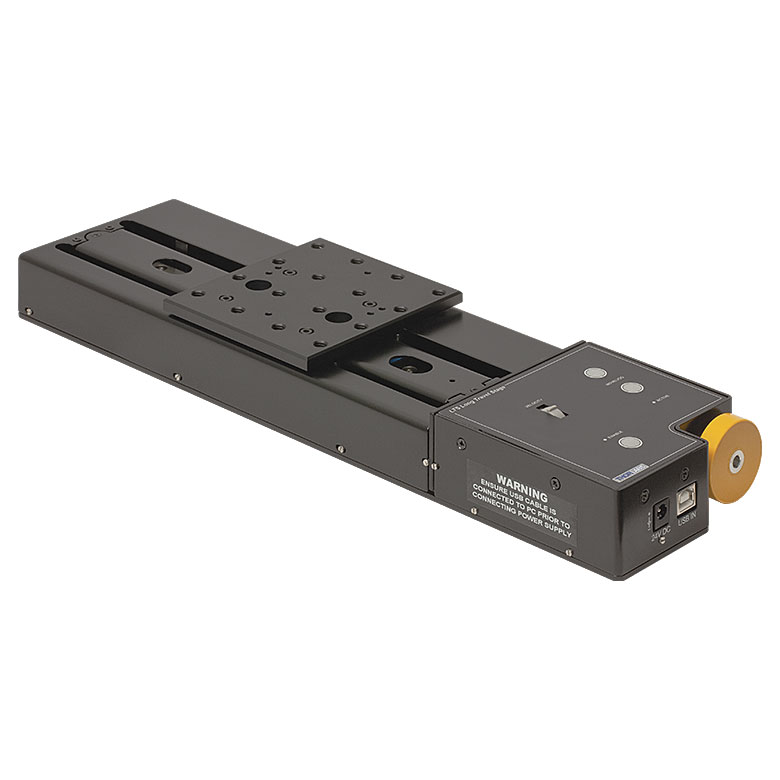
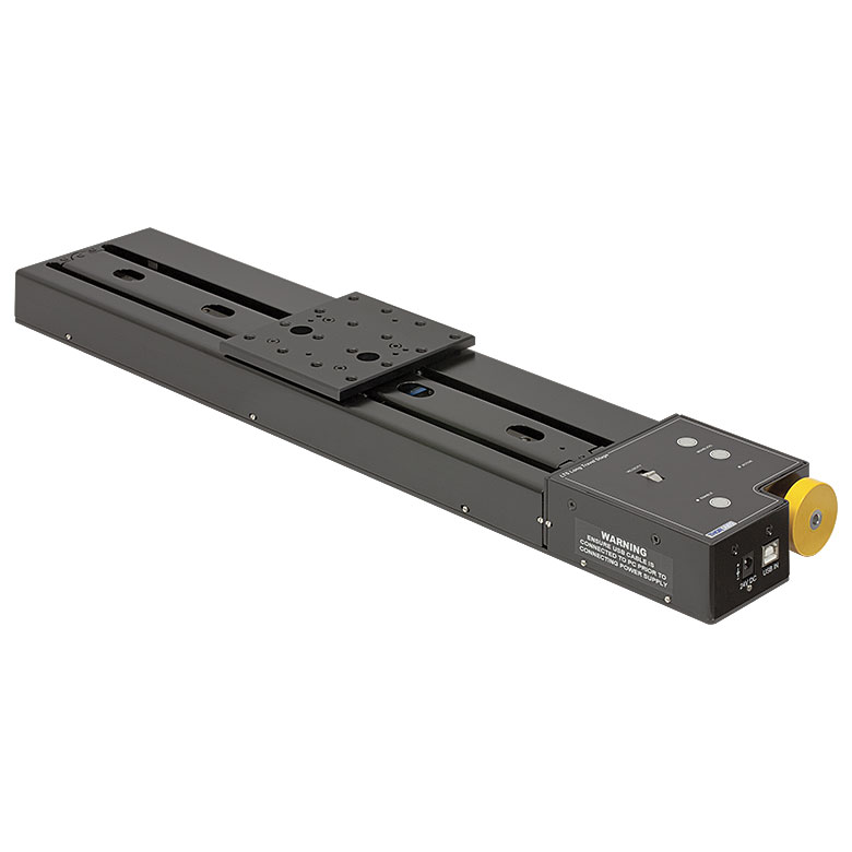
Item # LPS710E(/M) consists of the following:
- LPS710 or LPS710/M Stage
- PPC001 Piezo Controller
- Power Supply with Region-Specific Power Cord
- USB Cable for Computer Connections
- Storage Case with Slots for Stage and All Optional Accessories
A microscope slide holder, mirror mount, and mounting plate are available separately. The box that houses the LPS710 stage has an insert to hold these optional accessories.
| Posted Comments: | |
Wesley Browne
(posted 2025-08-18 17:29:07.96) All of a sudden we are getting an error message when we run a sequence in kinesis "Command error: Command failed to complete in time (Function Name - Invoke)" (was working fine up to then). Its seems like it is still moving and it works when controlling position manually with the up and down buttons. Can't find the error in the manual. spolineni
(posted 2025-08-26 12:08:46.0) Thank you for contacting us about the error message you’ve encountered in Kinesis. I will personally get in touch with you to assist with troubleshooting and resolve this issue. Fred Couweleers
(posted 2025-07-08 12:00:32.383) is it possible to use this stage "upside-down" (so the white arrow on the side of the housing points against the gravity vector)? tschofield
(posted 2025-07-16 06:42:03.0) Thank you for reaching out. We don't have any test data or records to draw upon regarding the use of the LPS710E upside-down. However, whilst it might not perform to specification, it would likely function to some extent that may be sufficient for your application. I will contact you directly to discuss your application in more detail. Bas Klement
(posted 2025-04-30 14:22:10.97) Dear sir/madam,
On the manual, A.2.4 Trigger Output; it is stated that the controller can provide a trigger output. Via the USER connector I could access this functionality using pins 5, 9 or 10 as ground and pin 11 as the trigger signal if I understand correctly.
I want to connect this controller to an Andor CCD to use this trigger, as a trigger for the camera for recording spectra after movement of the stage. The CCD requires a TTL trigger for triggering the camera so this could work.
I'm inquiring about this as it states on the page of this controller + stage, under 'pin diagrams' and in the manual that this functionality is 'for future use'.
Alternatively, is there perhaps already a python script in your possession or that you know of, which can control this piezo stage controller directly, or which can connect to the Kinesis software in order to control motion of the stage? Then a script could be written which moves the stage and thereafter triggers the camera, all through python.
I'm also open to hearing about other methods people use to do such experiments.
Thanks in advance and I look forward to hearing from you.
Kind regards,
Bas cstroud
(posted 2025-07-11 10:21:01.0) Thanks for reaching out. We have contacted you directly to discuss this further. user
(posted 2025-03-25 14:24:54.103) Hello, the stage appears to be designed to mount vertically and for the piezo to drive a vertical displacement. I am wondering if there are any issues with mounting this horizontally so that I can have horizontal displacement. spolineni
(posted 2025-04-02 06:18:54.0) Thank you for contacting us. I will personally reach out to discuss your requirements and offer further guidance and assistance. Gilbert Schuurman
(posted 2024-11-04 14:28:16.11) Hello,
I was wondering if this controller LPS710E/M also has a programmable waveform generation capability. I remember I saw this on your website in combination with another piezo controller but I can't seem to find anything about this anymore.
I see that the Kinesis API has functions for it (e.g. StartLUTwave). I also remember there were limitation in waveform length and temporal resolution but, again, I can't find it anymore.
Thank you for your assistance. dnewnham
(posted 2024-11-07 06:04:05.0) Thank you for your inquiry, I will reach out to you directly to discuss your application user
(posted 2023-06-08 21:44:09.553) Hi, is it compatible with rough vacuum (~0.1 Torr)? do'neill
(posted 2023-06-12 08:50:27.0) Response from Daniel at Thorlabs. No part of this stage has been tested for vacuum compatibility and unfortunately we can not say if it will work at any vacuum as there are several components that will outgas. petermarkwell
(posted 2018-03-29 12:21:33.01) Hi I'm looking to possibly purchase this as part of uni project. I want to know if travel distance can be lowered to for example 250um and resonant frequency can be lowered to for example 10Hz? YLohia
(posted 2018-03-30 05:13:52.0) Response from Yashasvi at Thorlabs USA: Hello, thank you for contacting Thorlabs. The travel distance can be chosen in the GUI settings to values much lower than 250µm, so you will be able to select your positioning with very high precision. The resonance frequency of a piezo is a physical value that cannot controlled by software setting; it requires changing the dimensions and layer design of the piezo stack. The value can be changed by adjusting the load on the piezo, with an increase in weight equating to a lower resonance frequency. We suggest limiting the weight to a maximum of roughly 3N for this stage (LPS710E). Please note that we do not recommend operating piezos at resonance as this produces significant heat build-up, which can quickly destroy the piezo. |
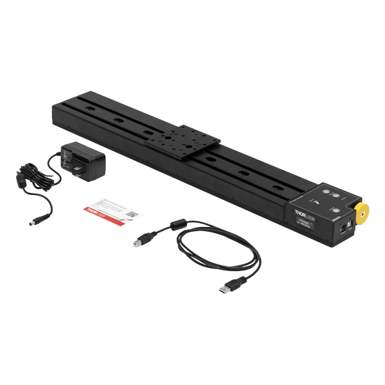
Motorized Linear Translation Stages
Thorlabs' motorized linear translation stages are offered in a range of maximum travel distances, from a stage with 20 µm of piezo translation to our 600 mm direct drive stage. Many of these stages can be assembled in multi-axis configurations, providing XY or XYZ translation. For fiber coupling applications, please see our multi-axis stages, which offer finer adjustment than our standard motorized translation stages. In addition to motorized linear translation stages, we offer motorized rotation stages and goniometers. We also offer manual translation stages.
Piezo Stages
These stages incorporate piezoelectric elements in a variety of drive mechanisms. ORIC® stages incorporate piezo inertia drives that use "stick-slip" friction properties to obtain extended travel ranges. Our Nanoflex™ translation stages use standard piezo chips along with manual actuators. Elliptec® stages use resonant piezo motors to push and pull the moving platform through resonant elliptical motion. Our LPS710E z-axis stage features a mechanically amplified piezo design and includes a matched controller.
| Piezoelectric Stages | ||||||
|---|---|---|---|---|---|---|
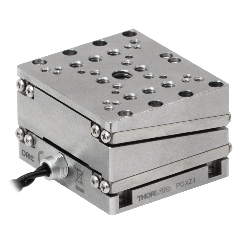
| Product Family | ORIC® PDXZ1 Closed-Loop 4.5 mm Vertical Stage |
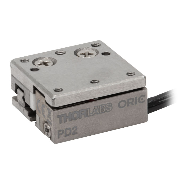
ORIC® PD2 Open-Loop 5 mm Stage |
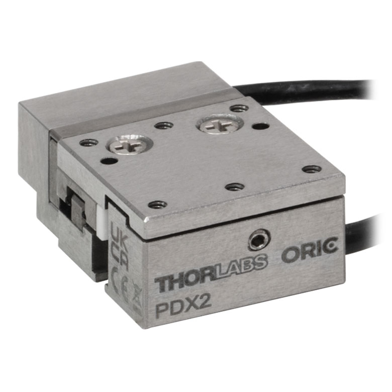
ORIC® PDX2 Closed-Loop 5 mm Stage |
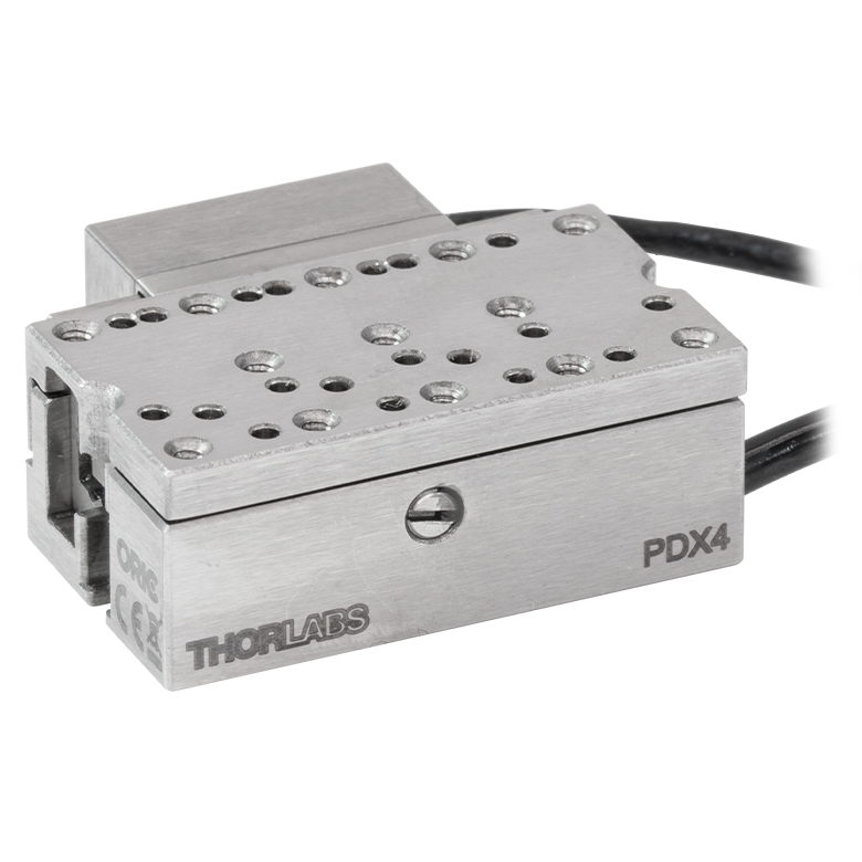
ORIC® PDX4 Closed-Loop 12 mm Stage |
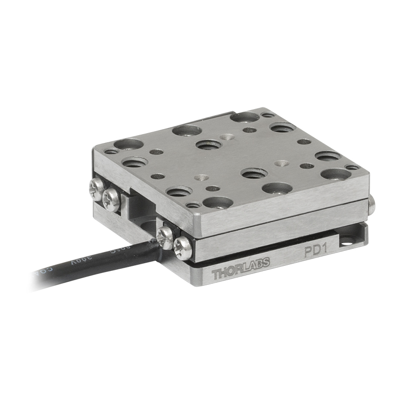
ORIC® PD1 Open-Loop 20 mm Stage |
ORIC® PD1D Open-Loop 20 mm Monolithic XY Stage |
| Click Photo to Enlarge |
 |
 |
 |
 |
 |
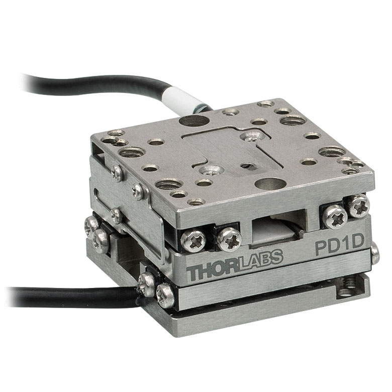 |
| Travel | 4.5 mm | 5 mm | 12 mm | 20 mm | ||
| Speed | 1 mm/s (Typ.)a | 10 mm/s (Typ. Max)b | 8 mm/s (Typ.)c | 15 mm/s (Typ.)a,c | 3 mm/s (Typ. Max)d | |
| Drive Type | Piezoelectric Inertia Drive | |||||
| Possible Axis Configurations | Z | X, XY, XYZ | XY, XYZ | |||
| Mounting Surface Size |
45.0 mm x 42.0 mm | 13.0 mm x 13.0 mm | 13.0 mm x 23.0 mm | 30.0 mm x 30.0 mm | ||
| Additional Details | ||||||
| Piezoelectric Stages | ||||||
|---|---|---|---|---|---|---|
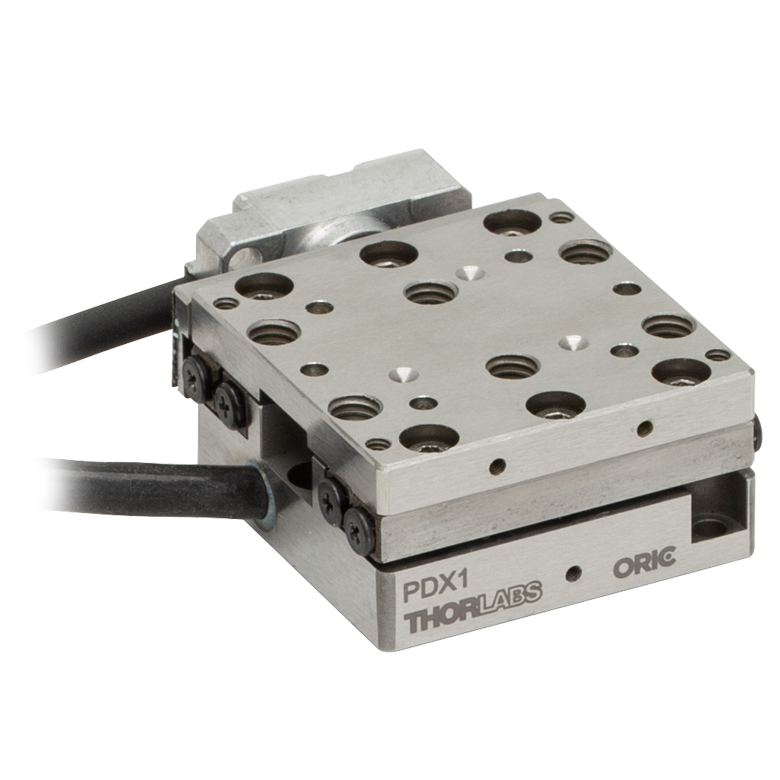
| Product Family | ORIC® PDX1 Closed-Loop 20 mm Stage |
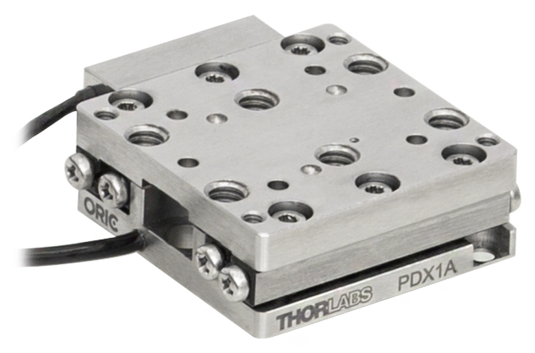
ORIC® PDX1A Closed-Loop 20 mm Stage Low-Profile |
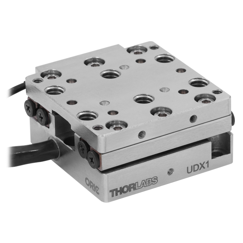
ORIC® UDX1 Ultrasonic Closed-Loop 20 mm Stage |
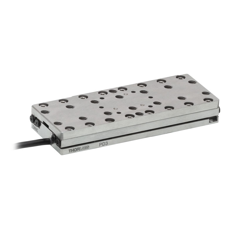
ORIC® PD3 Open-Loop 50 mm Stage |
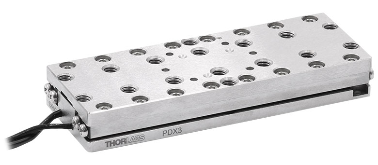
ORIC® PDX3 Closed-Loop 50 mm Stage |
|
| Click Photo to Enlarge |
 |
 |
 |
 |
 |
|
| Travel | 20 mm | 50 mm | ||||
| Speed | 20 mm/s (Typ. Max)a | 10 mm/s (Typ.)b | 100 mm/s (Typ. Max)c | 10 mm/sd | 10 mm/s (Typ. Max)b | |
| Drive Type | Piezoelectric Inertia Drive | Ultrasonic Piezoelectric Drive | Piezoelectric Inertia Drive | |||
| Possible Axis Configurations | X, XY, XYZ | |||||
| Mounting Surface Size |
30.0 mm x 30.0 mm | 80.0 mm x 30.0 mm | ||||
| Additional Details | ||||||
| Piezoelectric Stages | |||||||
|---|---|---|---|---|---|---|---|
| Product Family | Nanoflex™ 20 µm Stage with 5 mm Actuator |
Nanoflex™ 25 µm Stage with 1.5 mm Actuator |
Compact Modular XRN25X 25 mm Stage |
Modular XR25X 25 mm Stage |
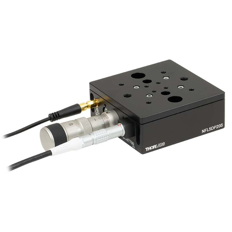
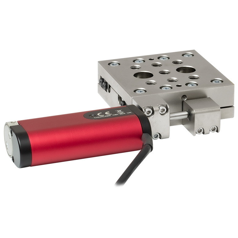
Elliptec® 28 mm Stage | Elliptec® 60 mm Stage | LPS710E 1.1 mm Vertical Stage |
| Click Photo to Enlarge |
 |
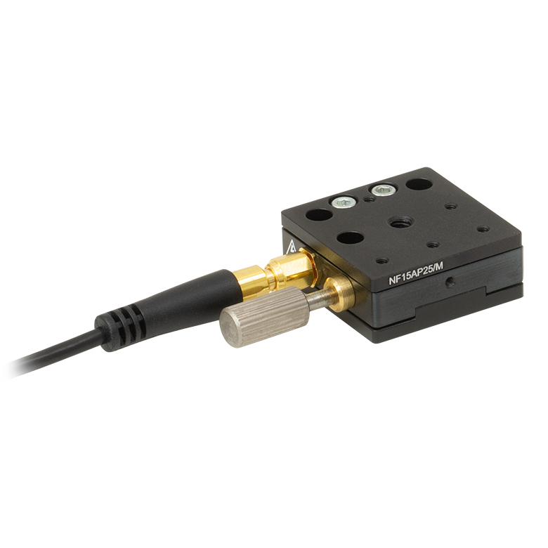 |
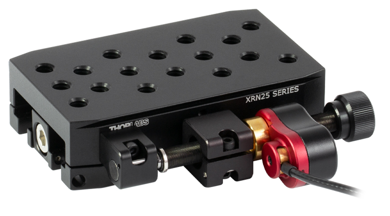 |
 |
 |
 |
 |
| Travel | 20 µm + 5 mm Manual | 25 µm + 1.5 mm Manual | 25 mm | 28 mm | 60.0 mm | 1.1 mm | |
| Maximum Velocity | - | ≤3.6 mm/mina | 180 mm/s | 90 mm/s | - | ||
| Drive Type | Piezo with Manual Actuator | Piezoelectric Inertia Drive | Resonant Piezoelectric Motor | Amplified Piezo | |||
| Possible Axis Configurations | X, XY, XYZ | X, XY, YZ, XZ, XYZ | X | Z | |||
| Mounting Surface Size | 75 mm x 75 mm | 30 mm x 30 mm | 85.0 mm x 50.7 mm | 110.0 mm x 75.7 mm | 15 mm x 15 mm | 21 mm x 21 mm | |
| Additional Details | |||||||
Stepper Motor Stages
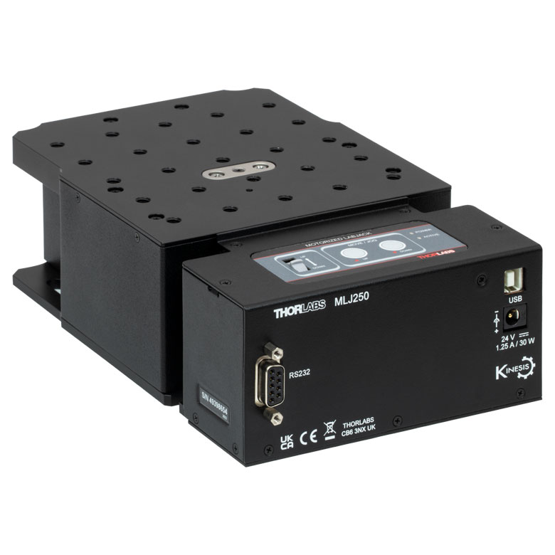
These translation stages feature removable or integrated stepper motors and long travel ranges up to 300 mm. Many of these stages either have integrated multi-axis capability (PLSXY) or can be assembled into multi-axis configurations (PLSX, LNR Series, NRT Series, and LTS Series stages). The MLJ150 stage also offers high load capacity vertical translation.
| Stepper Motor Stages | |||||
|---|---|---|---|---|---|
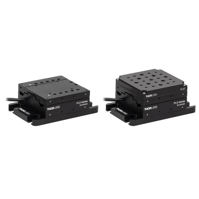
| Product Family | PLSX with and without PLST(/M) Top Plate 1" Stage |
PLSXY with and without PLST(/M) Top Plate 1" Stage |
LNR Series 25 mm Stage |
LNR Series 50 mm Stage |
|
| Click Photo to Enlarge |
 |
 |
 |
 |
|
| Travel | 1" | 25 mm | 50 mm | ||
| Maximum Velocity | 7.0 mm/s | 2.0 mm/s | 50 mm/s | ||
| Possible Axis Configurations |
X, XY | X, XY, XYZ | X, XY, XYZ | ||
| Mounting Surface Size |
3" x 3" | 60 mm x 60 mm | 100 mm x 100 mm | ||
| Additional Details | |||||
| Stepper Motor Stages | |||||||
|---|---|---|---|---|---|---|---|
| Product Family | NRT Series 100 mm Stage |
NRT Series 150 mm Stage |
LTS Series 150 mm Stage |
LTS Series 300 mm Stage |
LTS Series 450 mm Stage |
MLJ250 50 mm Vertical Stage |
|
| Click Photo to Enlarge |
 |
 |
 |
 |
 |
 |
|
| Travel | 100 mm | 150 mm | 150 mm | 300 mm | 400 mm | 50 mm | |
| Maximum Velocity | 30 mm/s | 50 mm/s | 3.0 mm/s | ||||
| Possible Axis Configurations |
X, XY, XYZ | X, XY, XYZ | X, XY | Z | |||
| Mounting Surface Size |
84 mm x 84 mm | 100 mm x 90 mm | 148 mm x 131 mm | ||||
| Additional Details | |||||||
DC Servo Motor Stages
Thorlabs offers linear translation stages with removable or integrated DC servo motors. These stages feature low profiles and many can be assembled in multi-axis configurations.
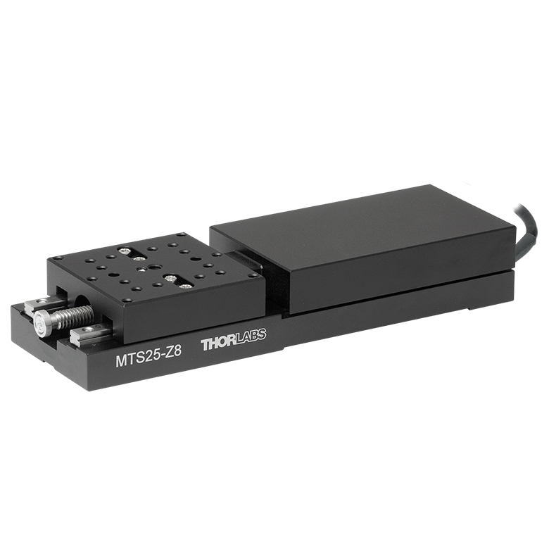
| DC Servo Motor Stages | ||||
|---|---|---|---|---|
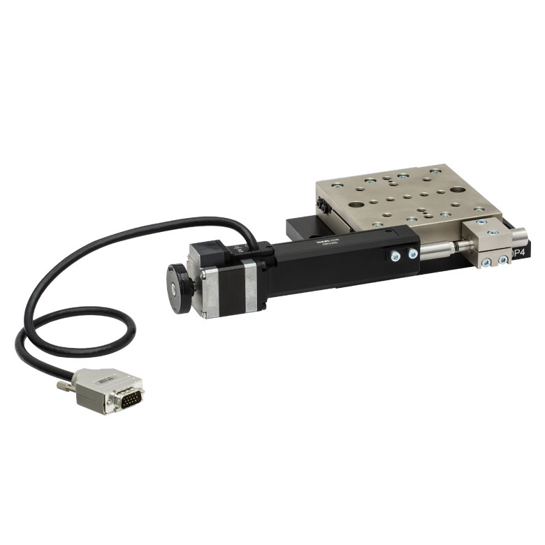
| Product Family | MT Series 12 mm Stages |
PT Series 25 mm Stages |
MTS Series 25 mm Stage |
MTS Series 50 mm Stage |
| Click Photo to Enlarge |
 |
 |
 |
 |
| Travel | 12 mm | 25 mm | 25 mm | 50 mm |
| Maximum Velocity | 2.6 mm/s | 2.4 mm/s | ||
| Possible Axis Configurations | X, XY, XYZ | X, XY, XYZ | ||
| Mounting Surface Size |
61 mm x 61 mm | 101.6 mm x 76.2 mm | 43 mm x 43 mm | |
| Additional Details | ||||
| DC Servo Motor Stages | ||||
|---|---|---|---|---|
| Product Family | M30 Series 30 mm Stage |
M30 Series 30 mm Monolithic XY Stage |
M150 Series 150 mm XY Stage |
KVS30 30 mm Vertical Stage |
| Click Photo to Enlarge |
 |
 |
 |
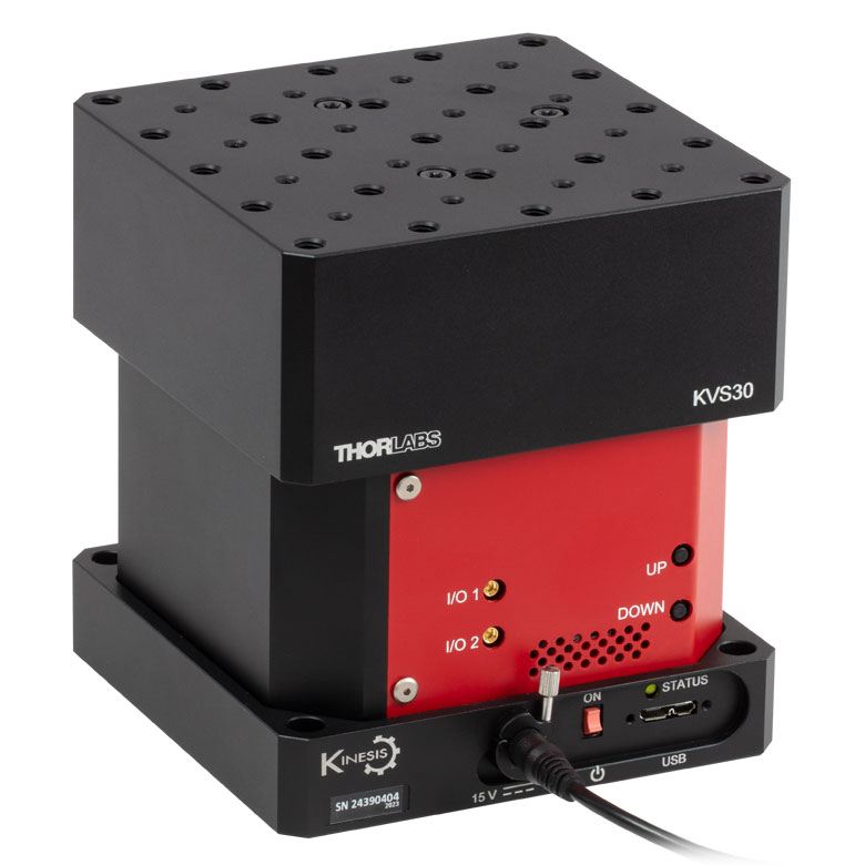 |
| Travel | 30 mm | 150 mm | 30 mm | |
| Maximum Velocity | 2.4 mm/s | X-Axis: 170 mm/s Y-Axis: 230 mm/s |
8.0 mm/s | |
| Possible Axis Configurations | X, Z | XY, XZ | XY | Z |
| Mounting Surface Size |
115 mm x 115 mm | 272.4 mm x 272.4 mm | 116.2 mm x 116.2 mm | |
| Additional Details | ||||
Direct Drive Stages
These low-profile stages feature integrated brushless DC servo motors for high speed translation with zero backlash. When no power is applied, the platforms of these stages have very little inertia and are virtually free running. Hence these stages may not be suitable for applications where the stage's platform needs to remain in a set position when the power is off. We do not recommend mounting these stages vertically.
| Direct Drive Stages | |||||
|---|---|---|---|---|---|
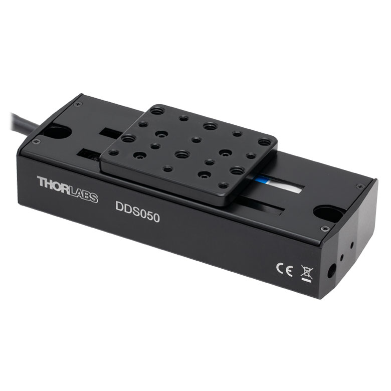
| Product Family | DDS Series 50 mm Stage |
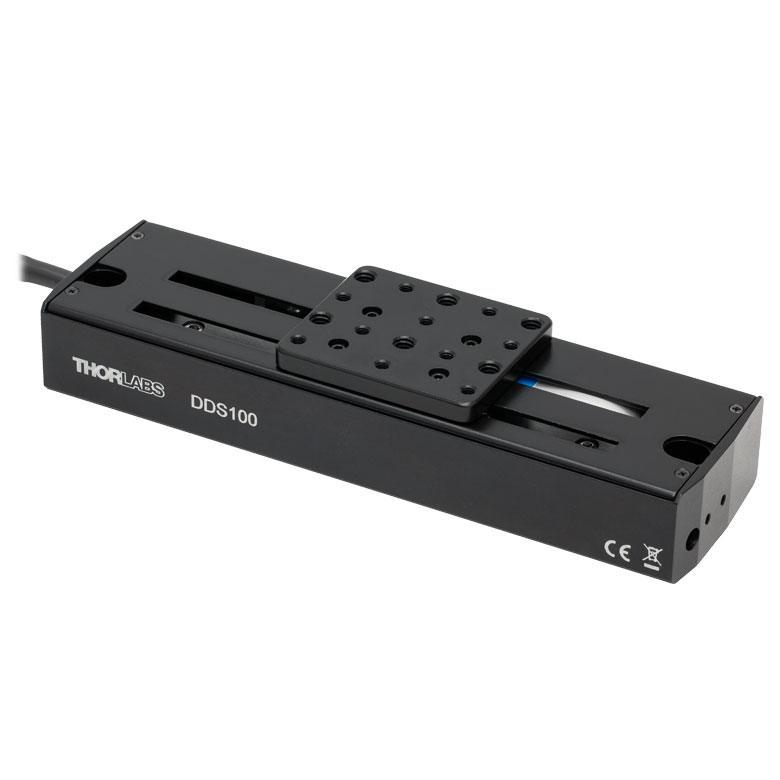
DDS Series 100 mm Stage |
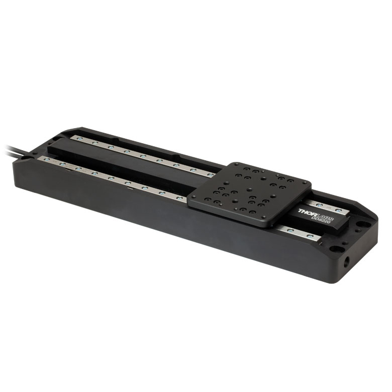
DDS Series 220 mm Stage |
DDS Series 300 mm Stage |
DDS Series 600 mm Stage |
| Click Photo to Enlarge |
 |
 |
 |
 |
 |
| Travel | 50 mm | 100 mm | 220 mm | 300 mm | 600 mm |
| Maximum Velocity | 500 mm/s | 300 mm/s | 400 mm/s | 400 mm/s | |
| Possible Axis Configurations | X, XY | X, XY | X | X | |
| Mounting Surface Size | 60 mm x 52 mm | 88 mm x 88 mm | 120 mm x 120 mm | ||
| Additional Details | |||||

 Zoom
Zoom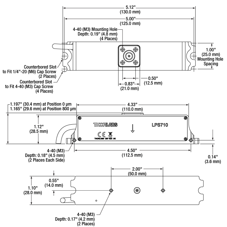
Click for Details
Figure G1.1 LPS710(/M) Mechanical Diagram
- Includes All Items Shown in Shipping List Tab
- Optional Accessories Available Below
The LPS710(/M) Piezo Stage and PPC001 Piezo Controller are sold as Item # LPS710E(/M) in a matched, factory-calibrated pair. Each is labeled with an identical serial number. It is not recommended to operate the piezo stage with a different controller.
For large periodic waveforms (i.e., sine waves that provide >200 µm of total displacement), the recommended drive frequencies are:
- ≤40 Hz for Loads up to 50 g
- ≤30 Hz for Loads from 50 g to 150 g
- ≤20 Hz for Loads from 150 g to 300 g

 Zoom
Zoom
Click to Enlarge
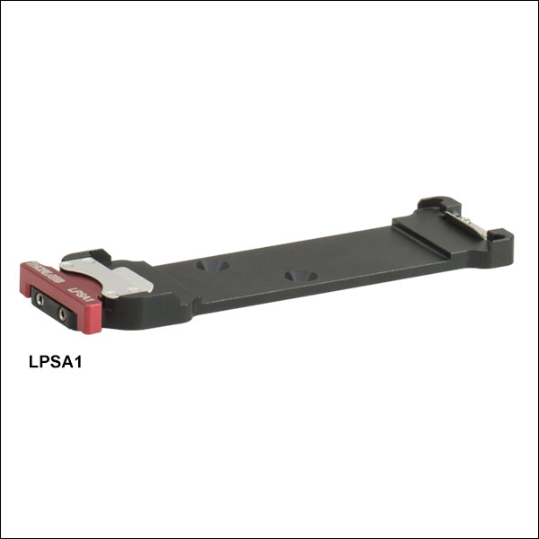
Figure G2.2 LPS710 Shown with the LPSA1 Slide Holder and Microscope Slide
- Mounts to LPS710(/M) Stage Using Included Countersunk Screws
- Holds 2.88" to 3.00" Long Microscope Slides up to 0.055" Thick and 1" Wide
- Retractable Tension Mount for Easy Slide Attachment or Removal
- Ideal for High-Speed Z-Stack Acquisition and Laser Scanning Microscopy
The LPSA1(/M) Microscope Slide Holder is designed to mount directly to the LPS710(/M) Amplified Piezo Stage; the pair is ideal for high-speed Z-stack acquisitions and laser scanning microscopy. It is compatible with microscope slides or test targets, as well as any rectangular optic from 2.88" (73.1 mm) to 3.00" (76.5 mm) long and up to 0.055" (1.4 mm) thick and 1.00" (25.4 mm) wide.
Two 4-40 (M3) countersunk cap screws are included to attach the slide holder to the mounting surface of the LPS710 Stage. Once attached, a slide can be placed into the holder by retracting the red, spring-loaded plunger, as shown in Figure G2.2. Please note that the slide holder does not have any through ports and therefore should not be used for transmitted light microscopy.

 Zoom
Zoom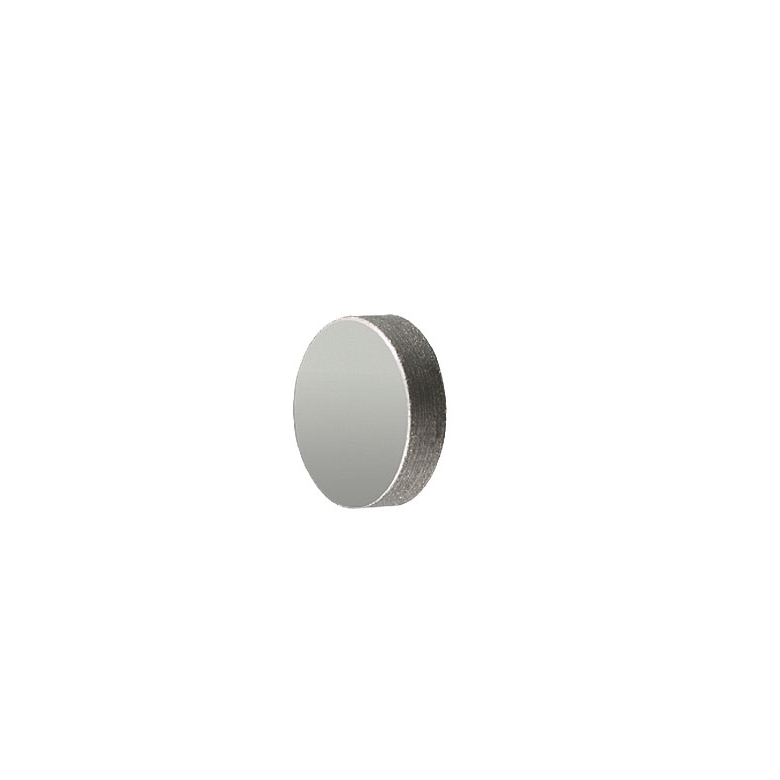
Click to Enlarge
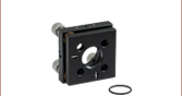
Figure G3.2 PF03-03-P01 Ø7 mm Mirror
Click to Enlarge
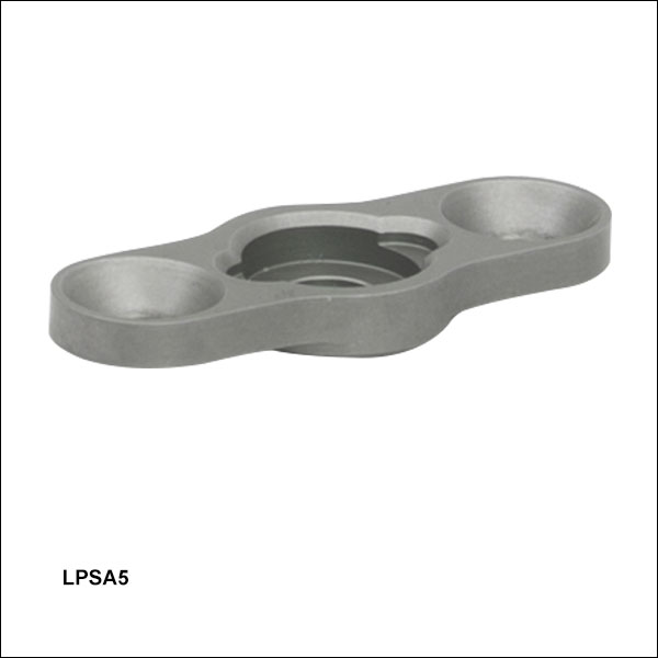
Figure G3.1 LPS710 Shown with the LPSA5 Mirror Mount and Glued-In
- Mounts to LPS710(/M) Stage Using Included Countersunk Screws
- Fixed Mount Designed to Accommodate Ø7 mm Mirrors
- Glue-In Design and Recessed Mounting Cell for Minimal Optic Distortion
The LPSA5(/M) Glue-In Fixed Optic Mount features a recessed optic cell that allows optics to be glued in place. It is designed to be lightweight (~3 g) and compact so that the stage can operate at higher frequencies. The adhesive optic mounting method ensures minimal optic surface distortion, providing optimum performance for sensitive applications such as interferometry or laser cavity construction. The mount is designed to hold a Ø7 mm Mirror, such as the PF03-03-P01 protected silver mirror provided below. We recommend Norland Optical Adhesive 61 (Item # NOA61, available below) for gluing optics to this mount.
Two 4-40 (M3) countersunk cap screws are included to attach the LPSA5 to the mounting surface of the LPS710 Stage, as shown in Figure G3.1.
| Mirror Specifications | ||||||||||
|---|---|---|---|---|---|---|---|---|---|---|
| Item # | Diameter | Thickness | Reflectance (Average) |
Reflectance Plot | Substrate | Surface Flatness | Surface Quality | Parallelism | Clear Aperture | |
| 12° AOI | 45° AOI | |||||||||
| PF03-03-P01 | 7 mm (0.28") +0.0 mm / -0.1 mm |
2.0 mm (0.08") ±0.2 mm |
>97.5% for 450 nm - 2 µm >96% for 2 - 20 µm |
 |
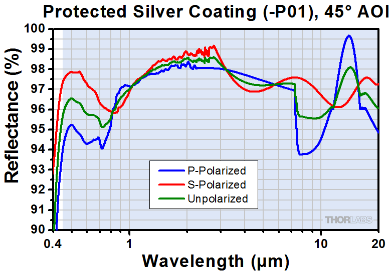 |
Fused Silica | λ/10 @ 633 nm | 40-20 Scratch-Dig | <3 arcmin | >90% of Diameter |

 Zoom
Zoom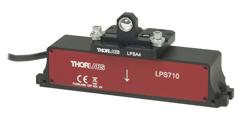 Click to Enlarge
 Figure G4.1 Fiber alignment accessories such as the HCS209 lens mount can be mounted onto the LPS710 using the LPSA4.
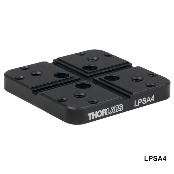
- Mounts to LPS710(/M) Stage Using Included 4-40 (M3) Cap Screws
- Two Crossed 3 mm Wide Central Keyways for Mounting Fiber Alignment Accessories
- Eight 6-32 (M3) Taps for Clamps and Mounting Cleats
- Four 8-32 (M4) Taps for General Mounting
The LPSA4(/M) Top Plate features two 3 mm wide central keyways in a crossed pattern to allow for rapid configuration when using our fiber alignment accessories, making this plate ideal for fiber launch applications. This plate can be secured onto the LPS710(/M) by inserting the included 4-40 (M3) cap screws into the counterbored through holes. By raising the deck height to approximately 62.5 mm using our post assemblies, the piezo stage and mounting plate can be used with our 3-axis Nanomax™, Microblock™, and Rollerblock™ stages, aiding in fiber alignment applications. Fiber alignment accessories can be secured to the plate by utilizing mounting cleats on two of the eight 6-32 (M3) taps, as seen in Figure G4.1. Four 8-32 (M4) mounting taps are available for additional mounting applications.
Please note that the weight of the mounting plate (20 g) and mounted components should not exceed the weight capacity of the LPS710(/M), 300 g.

 Zoom
Zoom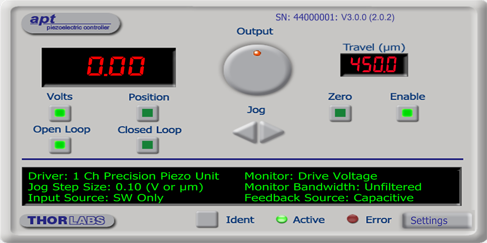
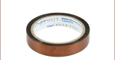
Recommended Optical Adhesive
NOA61 is recommended because of its excellent glass-metal adhesion and low-stress mounting. However, other UV-curing adhesives are available that provide faster curing times or greater flexibility for environments with large temperature fluctuations. Please see our complete presentation for details.
- Low Shrinkage (1.5%) and Low Stress
- Strong Glass-Metal Bond is Ideal for Use with Optics
- Recommended UV Curing Intensity >2 mW/cm2 @ 365 nm
The NOA61 Optical Adhesive is a clear, one-part adhesive that contains no solvents. When exposed to UV light, it gels in seconds and cures fully in minutes to give a tough resilient bond. It has been optimized to adhere optical glass to metal with very little stress. To cure this optical adhesive, it must be exposed to UV light. Thorlabs offers a UV curing system that provides an intensity up to 600 mW/cm2.
NOA61 optical adhesive is designed to give the best possible bond to glass surfaces and may be polished after curing. It meets Federal Specification MIL-A-3920 for optical adhesives and is approved for use on all government contracts specifying such adhesives. This adhesive has excellent adhesion to metal, fiberglass and glass-filled plastic.
Shelf Life
These UV-curing adhesives have a shelf life of approximately 8 months. This time frame begins on the date the epoxy was packaged at the manufacturer. Upon receipt by the end user, Thorlabs guarantees that the remaining shelf life will be at least 3 months.
| Item # | Adhesion | Viscosity @ 25 °C | na | Tensile Strength | Shore D Hardness |
Net Weightb |
||
|---|---|---|---|---|---|---|---|---|
| Glass | Metal | Plastic | ||||||
| NOA61 | Excellent | Excellent | Fair | 300 CPS | 1.56 | 3,000 psi | 85 | 1 ± 0.07 oz (28 ± 2 g) |