 Products Home
12 mm (0.47") Motorized Translation Stages
- 12 mm (0.47") of Travel per Axis
- 1/4"-20 or M6 Tapped Holes for Mounting Standard Optomechanics
- Sold in Single-Axis and XYZ Configurations
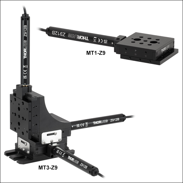
MT1-Z9
1-Axis Stage
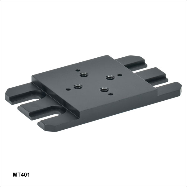
MT401
Breadboard Mounting Adapter
MT405
Side-Mounted Actuator Adapter
MT3-Z9
3-Axis Stage


Please Wait
| Key Specificationsa | |
|---|---|
| Travel Range | 12 mm (0.47") |
| Velocity (Max)b | 2.6 mm/s |
| Uncompensated Backlash | 13 µm |
| Residual Backlash After Compensationc | 0.7 µm |
| Min Repeatable Incremental Movement | 0.2 µm |
| Uncompensated/Compensated Bidirectional Repeatability | ±7 µm / ±0.7 µm |
| Horizontal Load Capacity (Max) | 20 lbs (9.0 kg) |
| Vertical Load Capacity (Max)d | Motor Pushing Down: 4.4 lbs (2.0 kg) |
| Motor Pushing Up: 10 lbs (4.5 kg) |
|
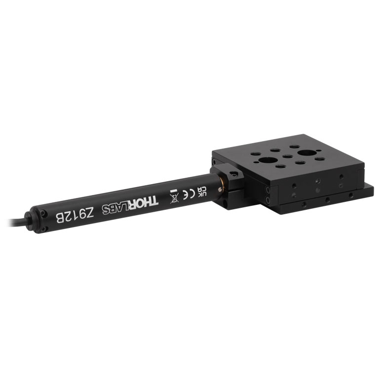
| Included Actuator | Z912B DC Motor |
| Cable Length | 485 mm (1.59 ft) |
| Recommended Controller | KDC101 |
| Motorized Linear Translation Stages | |
|---|---|
| 12 mm | Standard |
| 25 mm | Compact |
| Standard | |
| TravelMax | |
| 50 mm | Compact |
| Direct-Drive Servo | |
| TravelMax | |
| Long Travel: 100 mm to 300 mm | |
Features
- 12 mm (0.47") Travel Range
- Carriage Contains Seven 1/4"-20 (M6) Taps
- Locking Screw Holds Stage in Place
- Adapters Available for Breadboard Mounting and XY, XZ, and XYZ Arrangements
- DC Servo Motor Actuator
Thorlabs' Motorized Translation Stages provide electronically controlled linear motion along a well-defined axis. The MT1-Z9 (MT1/M-Z9) Single-Axis Stage provides 12 mm (0.47") of travel along one axis, while the MT3-Z9 (MT3/M-Z9) Three-Axis Stage provides travel in three dimensions. The three-axis stages are composite products made up of three MT1-Z9 (MT1/M-Z9) Single-Axis Stages connected with an MT401 Base Plate and an MT402 Right-Angle Bracket (sold separately below). Each stage is equipped with a 1.00" x 1.00" (25.0 mm x 25.0 mm) tapped hole matrix that includes seven 1/4"-20 (M6) taps for compatibility with standard optomechanics.
The moving platform contains holes for alignment pins that ensure orthogonality when the stage is stacked with other stages or connected to our accessories. Horizontal loads of 20 lbs (9 kg) and vertical loads of 4.4 lbs (2.0 kg), when the motor is pushing down, or 10 lbs (4.5 kg), when pushing up, are supported by the actuator's inline 67.49:1 planetary gear head. Since the MT3-Z9 (MT3/M-Z9) Three-Axis Stages have the vertical actuator pushing down, the vertical load for these is 4.4 lbs (2.0 kg). The stages feature hardened steel linear bearings for precision motion and long life.
Mounting Adapters and Stage Combinations
Thorlabs' adapter plates and brackets provide a convenient way to mount the MT1-Z9 on an optical table or breadboard; to allow several stages to be combined in XY, XZ, or XYZ configurations; and to reduce the overall length of the stage by repositioning the stage's actuator. Photos of these adapters in use are shown below.
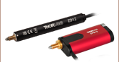
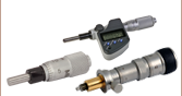
Included and Compatible Actuators
The included Z912B DC Servo Actuator features a 485 mm (1.59 ft) cable length, an internal limit switch to prevent travel outside of the intended range, and an encoder that provides 29 nm resolution (see the Specs tab for additional details). These actuators attach to the stage using a flexure clamp that tightens around the Ø3/8" barrel. If desired, the Z912B Actuators can be replaced by any manual or motorized 12 mm (0.47") actuator that includes a Ø3/8" barrel, including stepper motor actuators and manual micrometers.
Controller Options
For low-power stages such as the MT1-Z9 (MT1/M-Z9), Thorlabs recommends the KDC101 DC Servo Motor Controller. Each KDC101 provides control for a single axis, with or without a PC. It is bundled with Thorlabs' Kinesis® software, which supplies out-of-the-box stage control from a PC and enables support for common programming interfaces like LabVIEW, LabWindows, and ActiveX. A USB cable is included with the KDC101. Power supplies are sold separately; options are listed below.
| Motor Specifications | |
|---|---|
| Motor Type | DC Servo |
| Cable Length | 485 mm (1.59 ft) |
| Motor Drive Voltage | 6 VDC |
| Feedback | Motor-Mounted Rotary Encoder |
| Encoder Counts per Lead Screw Revolution | 34,555 |
| Planetary Gear Head Ratio | 67.49:1 |
Resolution Calculation
For the Z912B Actuator, there are 512 encoder counts per revolution of the motor. The output shaft of the motor goes into a 67.49:1 planetary gear head. This requires the motor to rotate 67.49 times to rotate the 1.0 mm pitch lead screw one revolution. The end result is the lead screw advances by 1.0 mm.
The linear displacement of the actuator per encoder count is given by
512 x 67.49 = 34,555 encoder counts per revolution of the lead screw,
whereas the linear displacement of the lead screw per encoder count is given by
1.0 mm / 34,555 counts = 2.9 x 10⁻⁵ mm (29 nm).
| Stage Specifications | |
|---|---|
| Translation | |
| Travel Range | 12 mm (0.47") |
| Uncompensated Backlash | 13 µm |
| Residual Backlash After Compensationa | 0.7 µm |
| Min Repeatable Incremental Movement | 0.2 µm |
| Homing Repeatability | ±6 µm |
| Uncompensated/Compensated Bidirectional Repeatabilityb | ±7 µm / ±0.7 µm |
| Resolution | 29 nm (See Calculation at Right) |
| Motion Parameters | |
| Velocity (Max)c | 2.6 mm/sec |
| Acceleration (Max) | 4 mm/s2 |
| Max Load Capacity | |
| Vertical Loadd | Motor Pushing Down: 4.4 lbs (2.0 kg) |
| Motor Pushing Up: 10 lbs (4.5 kg) | |
| Horizontal Load | 20 lbs (9.0 kg) |
| Orthogonality | |
| Angular Deviation | <250 µrad |
| Absolute On-Axis Accuracy | 95 µm |
| Percentage Accuracy (Max) | 0.82% |
| Physical | |
| Dimensionse | 7.78" x 2.41" x 0.81" (197.7 mm x 61.2 mm x 20.6 mm) |
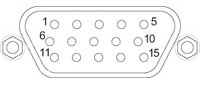
Z912B Connector Pin Out
D-Type Male
| Pin | Description | Pin | Description |
|---|---|---|---|
| 1 | Ground (Limit and Vcc) | 9 | Resistive Identification |
| 2 | Forward Limit | 10 | Vcc (+5 V DC) |
| 3 | Reverse Limit | 11 | Encoder Channel A |
| 4 | Reserved for Future Use | 12 | Reserved for Future Use |
| 5 | Motor (-) | 13 | Encoder Channel B |
| 6 | Reserved for Future Use | 14 | Pin 2 Ident EEPROM |
| 7 | Motor (+) | 15 | Pin 1 Ident EEPROM |
| 8 | Reserved for Future Use |
Thorlabs offers two platforms to drive our wide range of motion controllers: our Kinesis® software package or the legacy APT™ (Advanced Positioning Technology) software package. Either package can be used to control devices in the Kinesis family, which covers a wide range of motion controllers ranging from small, low-powered, single-channel drivers (such as the K-Cubes™ and T-Cubes™) to high-power, multi-channel, modular 19" rack nanopositioning systems (the APT Rack System).
The Kinesis Software features .NET controls which can be used by 3rd party developers working in the latest C#, Visual Basic, LabVIEW™, or any .NET compatible languages to create custom applications. Low-level DLL libraries are included for applications not expected to use the .NET framework. A Central Sequence Manager supports integration and synchronization of all Thorlabs motion control hardware.
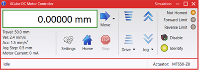
Kinesis GUI Screen
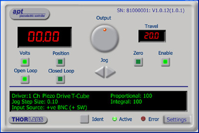
APT GUI Screen
Our legacy APT System Software platform offers ActiveX-based controls which can be used by 3rd party developers working on C#, Visual Basic, LabVIEW™, or any Active-X compatible languages to create custom applications and includes a simulator mode to assist in developing custom applications without requiring hardware.
By providing these common software platforms, Thorlabs has ensured that users can easily mix and match any of the Kinesis and APT controllers in a single application, while only having to learn a single set of software tools. In this way, it is perfectly feasible to combine any of the controllers from single-axis to multi-axis systems and control all from a single, PC-based unified software interface.
The software packages allow two methods of usage: graphical user interface (GUI) utilities for direct interaction with and control of the controllers 'out of the box', and a set of programming interfaces that allow custom-integrated positioning and alignment solutions to be easily programmed in the development language of choice.
A range of video tutorials is available to help explain our APT system software. These tutorials provide an overview of the software and the APT Config utility. Additionally, a tutorial video is available to explain how to select simulator mode within the software, which allows the user to experiment with the software without a controller connected. Please select the APT Tutorials tab above to view these videos.
Software
Kinesis Version 1.14.47
The Kinesis Software Package, which includes a GUI for control of Thorlabs' Kinesis and APT™ system controllers.
Also Available:
- Communications Protocol
Software
APT Version 3.21.6
The APT Software Package, which includes a GUI for control of Thorlabs' APT™ and Kinesis system controllers.
Also Available:
- Communications Protocol
The APT video tutorials available here fall into two main groups - one group covers using the supplied APT utilities and the second group covers programming the APT System using a selection of different programming environments.
Disclaimer: The videos below were originally produced in Adobe Flash. Following the discontinuation of Flash after 2020, these tutorials were re-recorded for future use. The Flash Player controls still appear in the bottom of each video, but they are not functional.
Every APT controller is supplied with the utilities APTUser and APTConfig. APTUser provides a quick and easy way of interacting with the APT control hardware using intuitive graphical control panels. APTConfig is an 'off-line' utility that allows various system wide settings to be made such as pre-selecting mechanical stage types and associating them with specific motion controllers.
APT User Utility
The first video below gives an overview of using the APTUser Utility. The OptoDriver single channel controller products can be operated via their front panel controls in the absence of a control PC. The stored settings relating to the operation of these front panel controls can be changed using the APTUser utility. The second video illustrates this process.
APT Config Utility
There are various APT system-wide settings that can be made using the APT Config utility, including setting up a simulated hardware configuration and associating mechanical stages with specific motor drive channels. The first video presents a brief overview of the APT Config application. More details on creating a simulated hardware configuration and making stage associations are present in the next two videos.
APT Programming
The APT Software System is implemented as a collection of ActiveX Controls. ActiveX Controls are language-independant software modules that provide both a graphical user interface and a programming interface. There is an ActiveX Control type for each type of hardware unit, e.g. a Motor ActiveX Control covers operation with any type of APT motor controller (DC or stepper). Many Windows software development environments and languages directly support ActiveX Controls, and, once such a Control is embedded into a custom application, all of the functionality it contains is immediately available to the application for automated operation. The videos below illustrate the basics of using the APT ActiveX Controls with LabVIEW, Visual Basic, and Visual C++. Note that many other languages support ActiveX including LabWindows CVI, C++ Builder, VB.NET, C#.NET, Office VBA, Matlab, HPVEE etc. Although these environments are not covered specifically by the tutorial videos, many of the ideas shown will still be relevant to using these other languages.
Visual Basic
Part 1 illustrates how to get an APT ActiveX Control running within Visual Basic, and Part 2 goes on to show how to program a custom positioning sequence.
LabVIEW
Full Active support is provided by LabVIEW and the series of tutorial videos below illustrate the basic building blocks in creating a custom APT motion control sequence. We start by showing how to call up the Thorlabs-supplied online help during software development. Part 2 illustrates how to create an APT ActiveX Control. ActiveX Controls provide both Methods (i.e. Functions) and Properties (i.e. Value Settings). Parts 3 and 4 show how to create and wire up both the methods and properties exposed by an ActiveX Control. Finally, in Part 5, we pull everything together and show a completed LabVIEW example program that demonstrates a custom move sequence.
Part 1: Accessing Online Help
Part 2: Creating an ActiveX Control
Part 3: Create an ActiveX Method
Part 4: Create an ActiveX Property
Part 5: How to Start an ActiveX Control
The following tutorial videos illustrate alternative ways of creating Method and Property nodes:
Create an ActiveX Method (Alternative)
Create an ActiveX Property (Alternative)
Visual C++
Part 1 illustrates how to get an APT ActiveX Control running within Visual C++, and Part 2 goes on to show how to program a custom positioning sequence.
MATLAB
For assistance when using MATLAB and ActiveX controls with the Thorlabs APT positioners, click here.
To further assist programmers, a guide to programming the APT software in LabVIEW is also available here.
| Posted Comments: | |
user
(posted 2022-09-13 13:28:34.57) What is the lifetime of the 1-axis stage MT1/M-Z8? The piezo inertia translation stage has a specified lifetime of >10 billion steps, but how about the MT1/M-Z8? For example, how many continuous cycles of 3 mm travel forward and 3 mm reverse (at 3 mm/s), with say 100 g horizontal load, can MT1/M-Z8 perform in its lifetime. Thanks in advance! cwright
(posted 2022-09-14 09:22:26.0) Response from Charles at Thorlabs: Thank you for your query. We do not specify a lifetime for this stage as it is dependent on how the stage is used (payload, travel range, duty cycle, etc). Therefore there is no single data point for life expectancy. A lifetime would create an expectation of life which may not be achieved under a users specific operating conditions and maintenance schedule. To ensure good performance and prevent wear we would suggest regreasing every 50,000 cycles or every 6 months. If only a limited travel range is used then periodically run the full travel to redistribute the grease. rubing Li
(posted 2022-08-01 21:44:38.197) Kinesis version 1.14.33 is installed, but when I use it to move the Z812B stage, the distance displayed by the KDC101 is not the same as what the software displays. DJayasuriya
(posted 2022-08-02 08:41:58.0) Thank you for your inquiry. This maybe a rounding issue with the software and the firmware. We will get in touch with you directly to resolve this. Tyler Fiebig
(posted 2021-12-09 17:47:40.54) The vertical stage relies entirely on a spring to return it back after being pushed out. This is a huge problem if the stage has any amount of weight on it. jgreschler
(posted 2021-12-14 09:57:06.0) Thank you for reaching out to Thorlabs. The vertical load capacity of the MT3-Z8 stage is 10 lbs or 4.5 kgs. If your application requires a load greater than that I'd recommend MLJ150 as an alternative stage with 44 lbs or 20 kg load capacity. Kim Hyeonjin
(posted 2021-02-16 11:27:28.353) Hello, recently I found that the stage is not going straight, but rotates every 1mm. Can we fix this issue? Thank you very much. asundararaj
(posted 2021-03-10 04:22:57.0) Thank you for contacting Thorlabs. I have directly contacted you to troubleshoot via email. Bryan Hennelly
(posted 2020-09-16 10:57:50.727) Just wondering if there is a micromanager plugin for the controller. I know the older version did work with MM but I cant get this one to. If not can you please supply serial commands to the controller. Thanks. llamb
(posted 2020-09-18 08:51:12.0) Thank you for contacting Thorlabs. Since Micromanager plugins are not developed by Thorlabs, we unfortunately cannot thoroughly support its usage. Serial commands can certainly be used though, and can be found in the Communications Protocol document, downloadable from here: https://www.thorlabs.com/software_pages/viewsoftwarepage.cfm?code=Motion_Control. I have reached out to you directly by email as well. Daniela Comelli
(posted 2020-03-23 11:09:25.363) Dear sirs,
I'm intersted in your MT1/M-Z8 linear translator.
I would like to know how Thorlabs defines unidirectional and bidirectional repeatibility for its linear translator and which are the estimated value for this specific model.
Similarly, how Thorlabs defined the backlash of its linear translator ?
My inquiry is related with the fact that I thought that bidirectional repeatibility and backlash are the same parameters, but probably I'm wrong.
Thanks in advance,
best regards,
Daniela Comelli llamb
(posted 2020-03-24 04:33:42.0) Hello Daniela, thank you for your feedback. Unidirectional repeatability is how close the stage can achieve the same position when commanded to approach that position in the same direction; bidirectional repeatability is defined the same way, but approaching that point from either direction. We unfortunately do not have a unidirectional repeatability spec for the Z812B motors used in the MT1/M-Z8 stages, though expect this to be smaller than the bidirectional repeatability spec. These repeatabiliity specs apply over the full travel range, while backlash is caused by clearance between gears or the lead screw. Backlash is always going to exist with these leadscrew-based motors, though using the backlash correction feature in our software will ensure that the commanded position is always approached from the same direction to avoid this backlash error. user
(posted 2019-11-25 18:19:52.38) Really need to upgrade your website in the "APT tutorials" section as most web browsers no longer support Adobe Flash Player. llamb
(posted 2019-11-26 12:13:31.0) Thank you for your feedback. We will look into updating our APT Tutorials. user
(posted 2019-04-11 11:37:30.323) Dear Sir/Madame,
Are there Python drivers written for the motion controllers, or would I have to write my own?
Kindest regards, llamb
(posted 2019-04-12 08:37:21.0) Thank you for contacting Thorlabs. While our motion control software can be used in Python, we do not officially support it at this time. However, we do have a few minimal working examples we can provide as a courtesy, including one in IronPython, one in CPython, and a serial command-based script. I will reach out to you directly with these examples. chuanyaozhou
(posted 2018-04-02 16:06:53.94) Dear Engineer,
I am Chuanyao Zhou from Dalian Institute of Chemical Physics, China. I am interested in your MT products. I want to use them in a vacuum (better than 10^-5 torr) chamber. I am wondering whether they are vacuum compatible and can be used in our case. Thanks!
best regards,
Chuanyao YLohia
(posted 2018-04-03 09:41:05.0) Hello Chuanyao, thank you for your interest in our products. While the MT1/M-Z8 is not vacuum-compatible (due to black anodizing and lack of vacuum grease/epoxy etc.), we may be able to offer a vacuum-compatible version as a special to you. We will reach out directly to you to discuss this further. hadi.abidin
(posted 2013-04-19 20:20:09.283) How will this linear stage perform when mounted vertically under low vacuum(100mbar).
Can you provide a quotation for a vacuum version of this stage tcohen
(posted 2013-04-25 11:08:00.0) Response from Tim at Thorlabs: The stage itself should be fine for this low vacuum. The motor, however, would likely require adding vacuum compatible greases. We will contact you with a quotation. klee
(posted 2009-10-01 12:32:45.0) A response from Ken at Thorlabs to kraghunath: The weight of the MT3-Z8 is about 3.2 lbs. The length of the motor cable is 0.5m. The length of the USB cable is 2m. kraghunath
(posted 2009-10-01 06:54:43.0) 1. what is the total weight of the MT3-Z8 with base plate
2. what is the typical length of RS 232 cable provided for control from TDC001 to MT3-Z8.
3. what is the typical length of USB cable provided for PC control to TDC001.
Raghunath jens
(posted 2009-06-19 09:04:18.0) A reply from Jens at Thorlabs: the calculated displacement is indeed 2.9 x 10⁻⁵mm which is the same as 29nm. The first number is given in millimeter which might be confusing so it is 2.9 x 10⁻⁸ meter. kadri
(posted 2009-06-18 22:17:23.0) I am thinking whether 29 nm or 29 micron is the correct value in the information below
"The linear displacement of the actuator per encoder count is given by
512 x 67 = 34,304 encoder counts per revolution of the lead screw,
whereas the linear displacement of the lead screw per encoder count is given by
1.0 mm / 34,304 counts = 2.9 x 10⁻⁵ mm (29 nm)." jens
(posted 2009-05-27 08:32:31.0) A reply from Jens at Thorlabs: the standard stage as offered on the web page is not designed for vaccuum application, we can however offer a custom version which will be unanodized, using vacuum compatible actuator, grease and epoxy. We will contact you with a quotation. rafal.rakowski
(posted 2009-05-27 08:18:33.0) Hello,
My question is: will be work this stage under vacuum ?
Thank you in advance for reply,
Best regards,
Rafal Rakowski, PhD
********************* Tyler
(posted 2008-06-05 15:56:03.0) A response from Tyler at Thorlabs to gogabis: An application engineer attempted to simulate the situation you described and found that the stage functioned without any issues, even when oriented upside down. They will be contacting you with more details regarding the simulation. Thank you for your interest in our products. gogabis
(posted 2008-06-05 06:10:20.0) I have MT1/M-Z6 and planning load it with substanshial moment (2kg*0.10cm not load specified in yours specification) and main problem upside down is it possible ? Will it be backslash problem ? stifout
(posted 2007-12-26 03:35:58.0) Is it possible to request MT1/M Translation Stage eqquipped with a step motor instead
of DC motor? If possible, how much such product will cost?
Thanks, A. Stifutkin |
Motorized Linear Translation Stages
Thorlabs' motorized linear translation stages are offered in a range of maximum travel distances, from a stage with 20 µm of piezo translation to our 600 mm direct drive stage. Many of these stages can be assembled in multi-axis configurations, providing XY or XYZ translation. For fiber coupling applications, please see our multi-axis stages, which offer finer adjustment than our standard motorized translation stages. In addition to motorized linear translation stages, we offer motorized rotation stages and goniometers. We also offer manual translation stages.
Piezo Stages
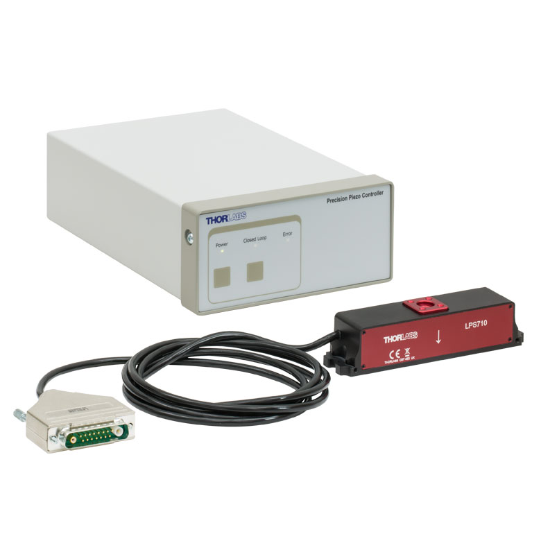
These stages incorporate piezoelectric elements in a variety of drive mechanisms. ORIC® stages incorporate piezo inertia drives that use "stick-slip" friction properties to obtain extended travel ranges. Our Nanoflex™ translation stages use standard piezo chips along with manual actuators. Elliptec® stages use resonant piezo motors to push and pull the moving platform through resonant elliptical motion. Our LPS710E z-axis stage features a mechanically amplified piezo design and includes a matched controller.
| Piezoelectric Stages | ||||
|---|---|---|---|---|
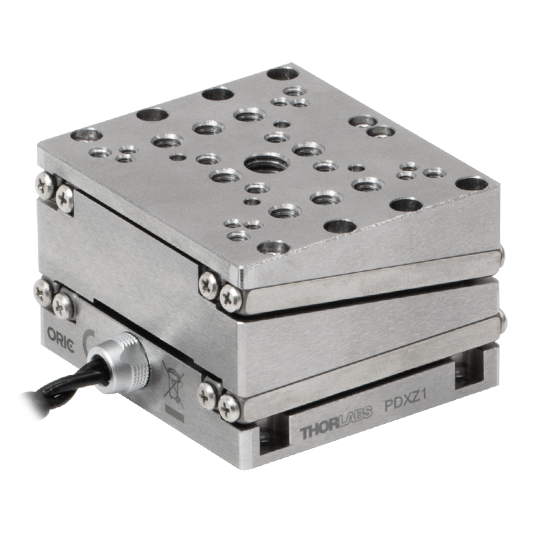
| Product Family | ORIC® PDXZ1 Closed-Loop 4.5 mm Vertical Stage |
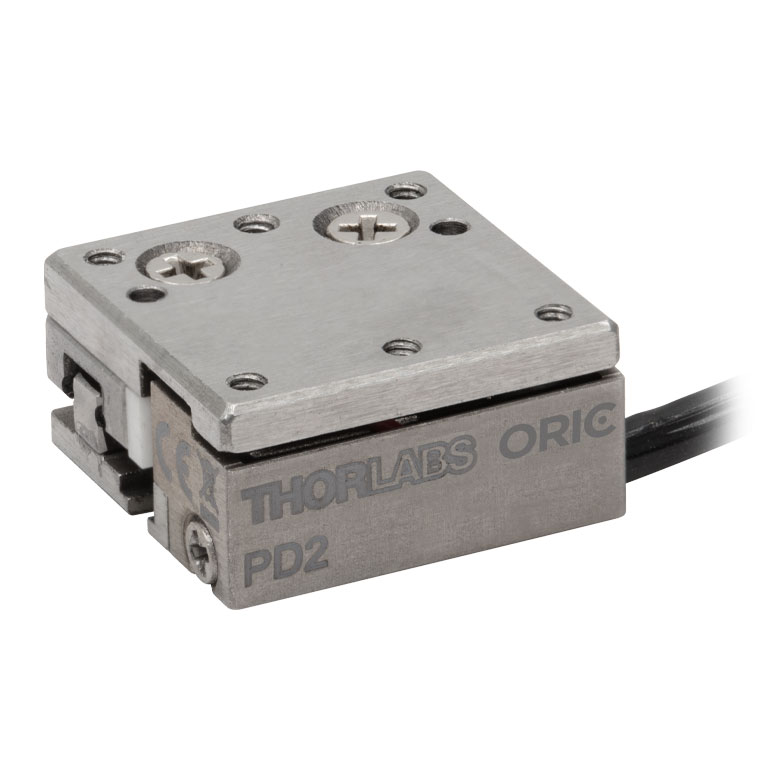
ORIC® PD2 Open-Loop 5 mm Stage |
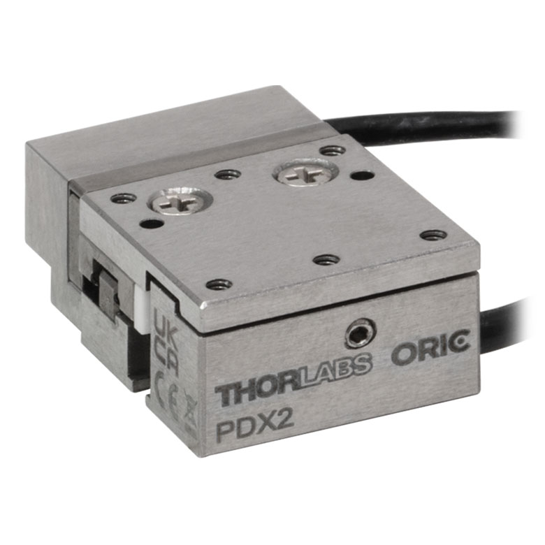
ORIC® PDX2 Closed-Loop 5 mm Stage |
|
| Click Photo to Enlarge |
 |
 |
 |
|
| Travel | 4.5 mm | 5 mm | ||
| Speed | 1 mm/s (Typ.)a | 10 mm/s (Typ. Max)b | 8 mm/s (Typ.)c | |
| Drive Type | Piezoelectric Inertia Drive | |||
| Possible Axis Configurations | Z | X, XY, XYZ | ||
| Mounting Surface Size |
45.0 mm x 42.0 mm | 13 mm x 13 mm | ||
| Additional Details | ||||
| Piezoelectric Stages | |||||
|---|---|---|---|---|---|
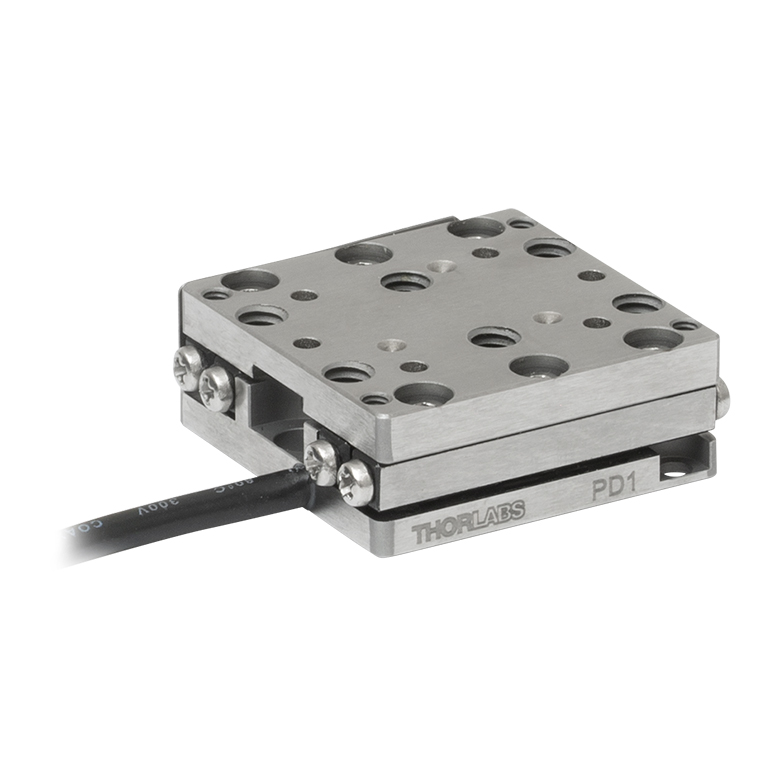
| Product Family | ORIC® PD1 Open-Loop 20 mm Stage |
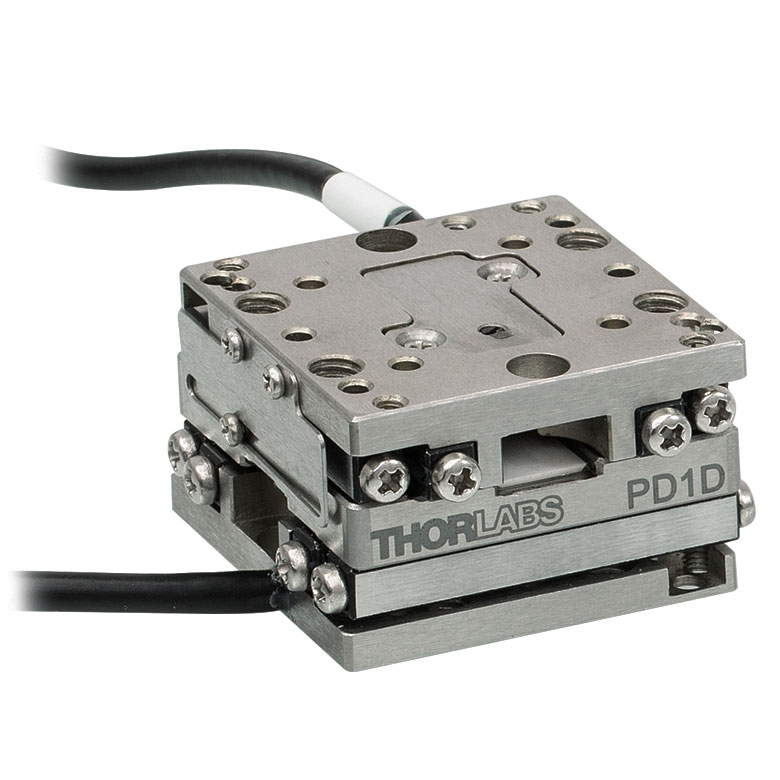
ORIC® PD1D Open-Loop 20 mm Monolithic XY Stage |
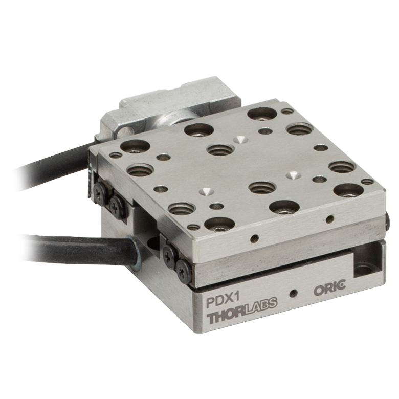
ORIC® PDX1 Closed-Loop 20 mm Stage |
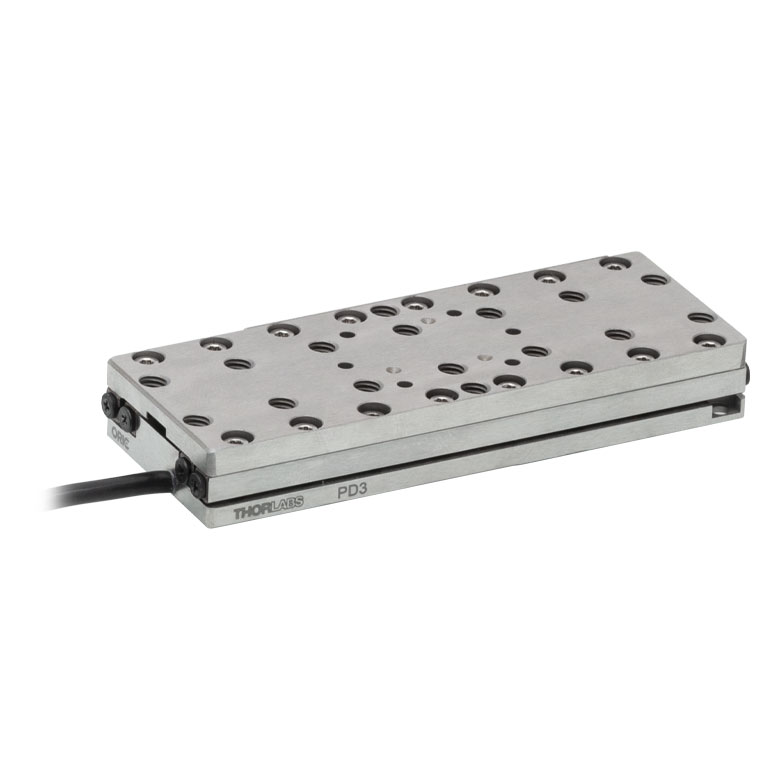
ORIC® PD3 Open-Loop 50 mm Stage |
|
| Click Photo to Enlarge |
 |
 |
 |
 |
|
| Travel | 20 mm | 50 mm | |||
| Speed | 3 mm/s (Typ. Max)a | 20 mm/s (Typ. Max)b | 10 mm/sc | ||
| Drive Type | Piezoelectric Inertia Drive | ||||
| Possible Axis Configurations | X, XY, XYZ | XY, XYZ | X, XY, XYZ | X, XY, XYZ | |
| Mounting Surface Size |
30 mm x 30 mm | 80 mm x 30 mm | |||
| Additional Details | |||||
| Piezoelectric Stages | ||||||
|---|---|---|---|---|---|---|
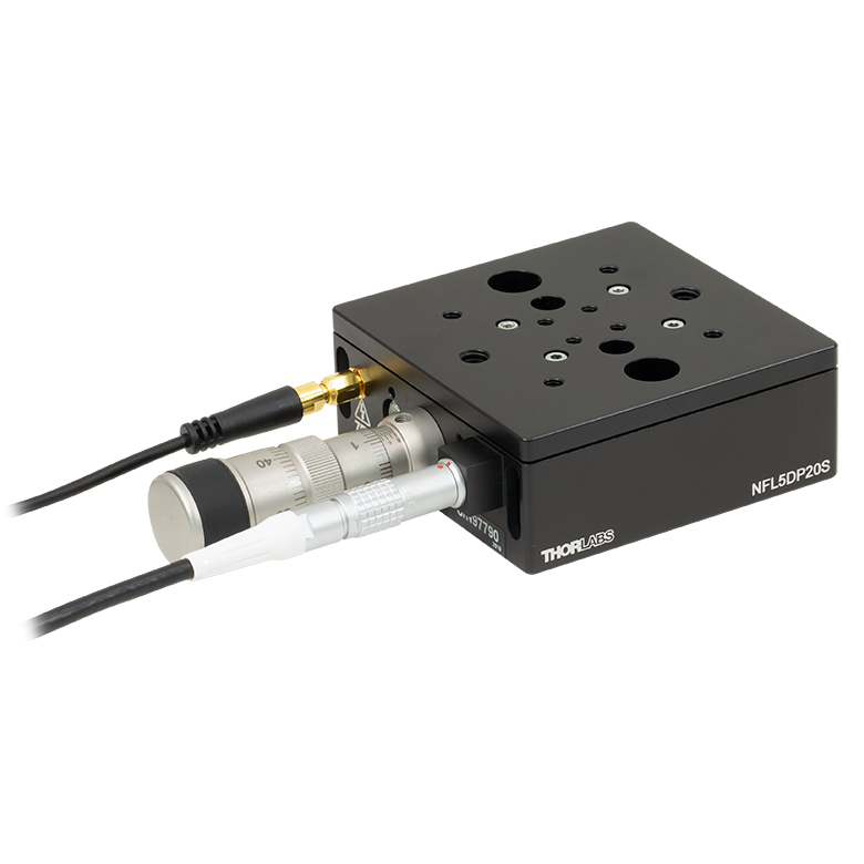
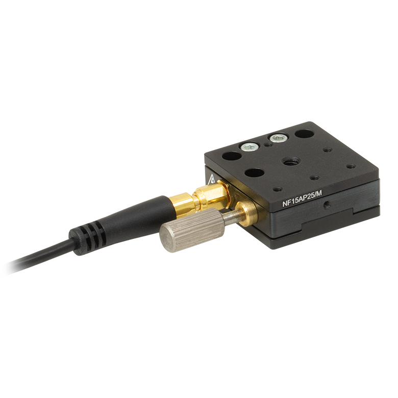
| Product Family | Nanoflex™ 20 µm Stage with 5 mm Actuator |
Nanoflex™ 25 µm Stage with 1.5 mm Actuator |
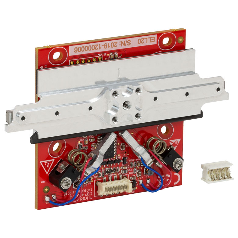
Elliptec® 28 mm Stage | Elliptec® 60 mm Stage | LPS710E 1.1 mm Vertical Stage | |
| Click Photo to Enlarge |
 |
 |
 |
 |
 |
|
| Travel | 20 µm + 5 mm Manual | 25 µm + 1.5 mm Manual | 28 mm | 60.0 mm | 1.1 mm | |
| Maximum Velocity | - | 180 mm/s | 90 mm/s | - | ||
| Drive Type | Piezo with Manual Actuator | Resonant Piezoelectric Motor | Amplified Piezo | |||
| Possible Axis Configurations | X, XY, XYZ | X | Z | |||
| Mounting Surface Size | 75 mm x 75 mm | 30 mm x 30 mm | 15 mm x 15 mm | 21 mm x 21 mm | ||
| Additional Details | ||||||
Stepper Motor Stages
These translation stages feature removable or integrated stepper motors and long travel ranges up to 300 mm. Many of these stages either have integrated multi-axis capability (PLSXY) or can be assembled into multi-axis configurations (PLSX, LNR Series, NRT Series, and LTS Series stages). The MLJ150 stage also offers high load capacity vertical translation.
| Stepper Motor Stages | |||||
|---|---|---|---|---|---|
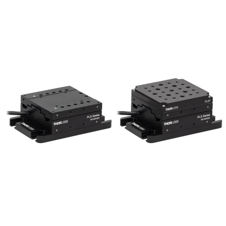
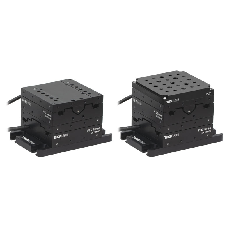
| Product Family | PLSX with and without PLST(/M) Top Plate 1" Stage |
PLSXY with and without PLST(/M) Top Plate 1" Stage |
LNR Series 25 mm Stage |
LNR Series 50 mm Stage |
|
| Click Photo to Enlarge |
 |
 |
 |
 |
|
| Travel | 1" | 25 mm | 50 mm | ||
| Maximum Velocity | 7.0 mm/s | 2.0 mm/s | 50 mm/s | ||
| Possible Axis Configurations |
X, XY | X, XY, XYZ | X, XY, XYZ | ||
| Mounting Surface Size |
3" x 3" | 60 mm x 60 mm | 100 mm x 100 mm | ||
| Additional Details | |||||
| Stepper Motor Stages | ||||||
|---|---|---|---|---|---|---|
| Product Family | NRT Series 100 mm Stage |
NRT Series 150 mm Stage |
LTS Series 150 mm Stage |
LTS Series 300 mm Stage |
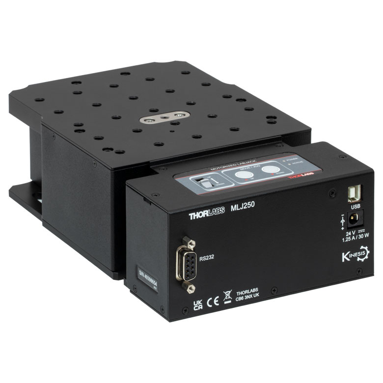
MLJ250 50 mm Vertical Stage |
|
| Click Photo to Enlarge |
 |
 |
 |
 |
 |
|
| Travel | 100 mm | 150 mm | 150 mm | 300 mm | 50 mm | |
| Maximum Velocity | 30 mm/s | 50 mm/s | 3.0 mm/s | |||
| Possible Axis Configurations |
X, XY, XYZ | X, XY, XYZ | Z | |||
| Mounting Surface Size |
84 mm x 84 mm | 100 mm x 90 mm | 148 mm x 131 mm | |||
| Additional Details | ||||||
DC Servo Motor Stages
Thorlabs offers linear translation stages with removable or integrated DC servo motors. These stages feature low profiles and many can be assembled in multi-axis configurations.
| DC Servo Motor Stages | ||||
|---|---|---|---|---|
| Product Family | MT Series 12 mm Stages |
PT Series 25 mm Stages |
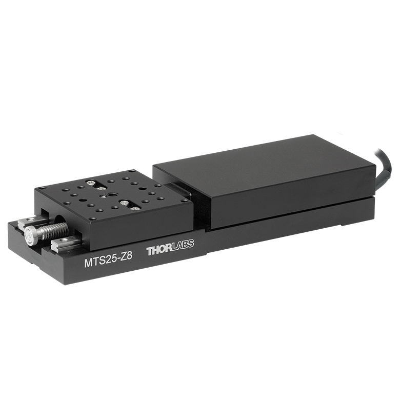
MTS Series 25 mm Stage |
MTS Series 50 mm Stage |
| Click Photo to Enlarge |
 |
 |
 |
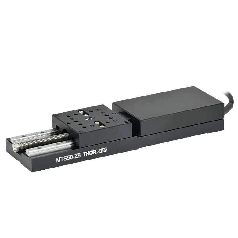 |
| Travel | 12 mm | 25 mm | 25 mm | 50 mm |
| Maximum Velocity | 2.6 mm/s | 2.4 mm/s | ||
| Possible Axis Configurations | X, XY, XYZ | X, XY, XYZ | ||
| Mounting Surface Size |
61 mm x 61 mm | 101.6 mm x 76.2 mm | 43 mm x 43 mm | |
| Additional Details | ||||
| DC Servo Motor Stages | ||||
|---|---|---|---|---|
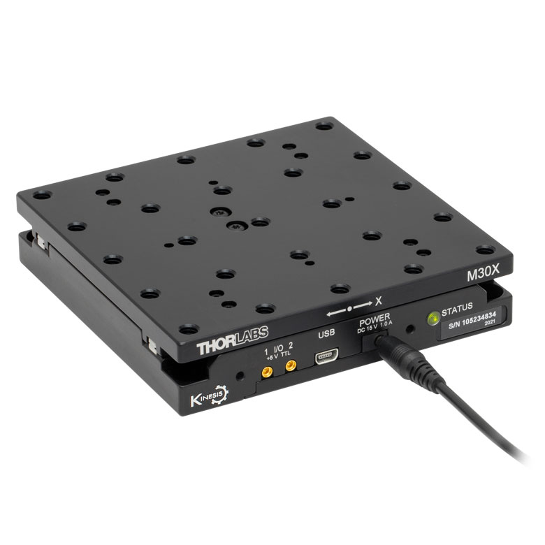
| Product Family | M30 Series 30 mm Stage |
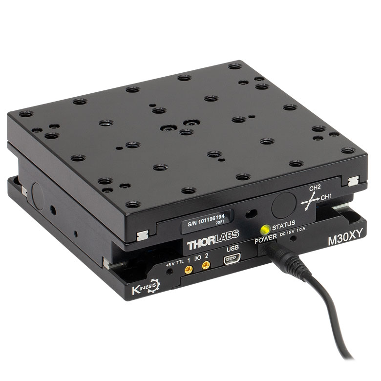
M30 Series 30 mm Monolithic XY Stage |
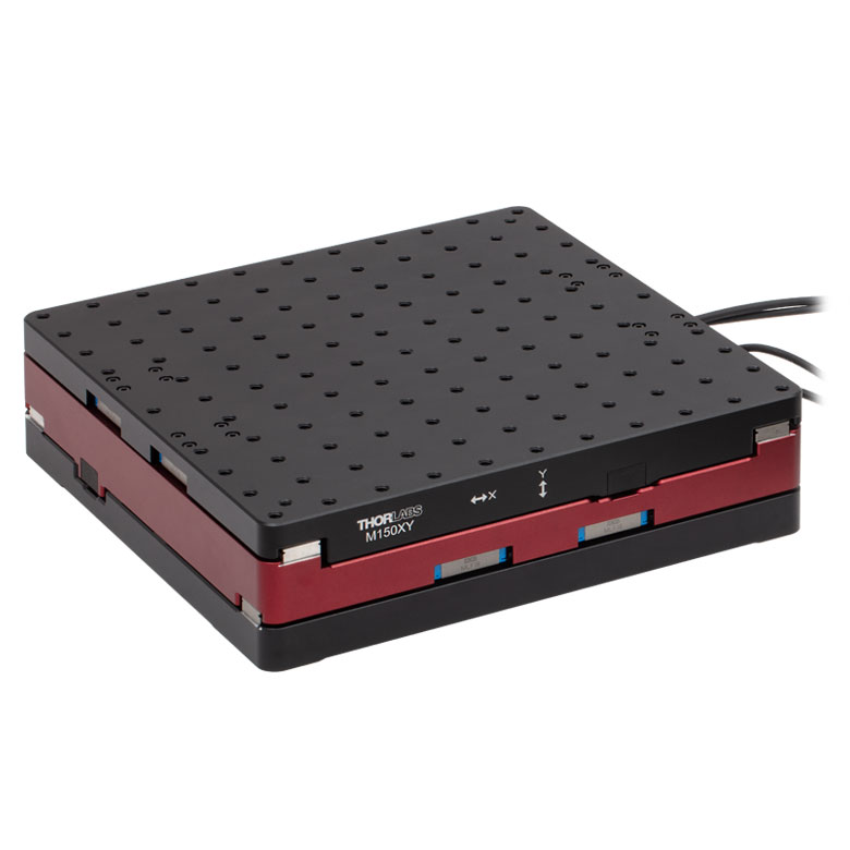
M150 Series 150 mm XY Stage |
KVS30 30 mm Vertical Stage |
| Click Photo to Enlarge |
 |
 |
 |
 |
| Travel | 30 mm | 150 mm | 30 mm | |
| Maximum Velocity | 2.4 mm/s | X-Axis: 170 mm/s Y-Axis: 230 mm/s |
8.0 mm/s | |
| Possible Axis Configurations | X, Z | XY, XZ | XY | Z |
| Mounting Surface Size |
115 mm x 115 mm | 272.4 mm x 272.4 mm | 116.2 mm x 116.2 mm | |
| Additional Details | ||||
Direct Drive Stages
These low-profile stages feature integrated brushless DC servo motors for high speed translation with zero backlash. When no power is applied, the platforms of these stages have very little inertia and are virtually free running. Hence these stages may not be suitable for applications where the stage's platform needs to remain in a set position when the power is off. We do not recommend mounting these stages vertically.
| Direct Drive Stages | |||||
|---|---|---|---|---|---|
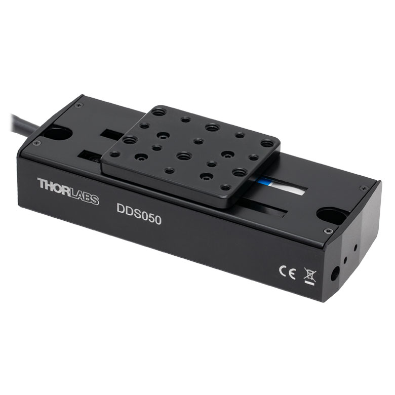
| Product Family | DDS Series 50 mm Stage |
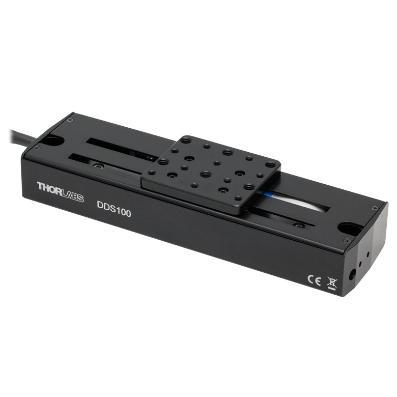
DDS Series 100 mm Stage |
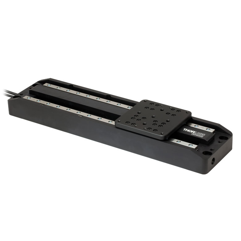
DDS Series 220 mm Stage |
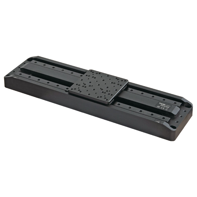
DDS Series 300 mm Stage |
DDS Series 600 mm Stage |
| Click Photo to Enlarge |
 |
 |
 |
 |
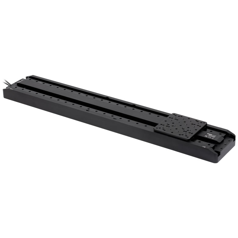 |
| Travel | 50 mm | 100 mm | 220 mm | 300 mm | 600 mm |
| Maximum Velocity | 500 mm/s | 300 mm/s | 400 mm/s | 400 mm/s | |
| Possible Axis Configurations | X, XY | X, XY | X | X | |
| Mounting Surface Size | 60 mm x 52 mm | 88 mm x 88 mm | 120 mm x 120 mm | ||
| Additional Details | |||||
 Motorized Translation Stages")
 Zoom
Zoom
Click to Enlarge
Schematic of Metric Single-Axis Stage
Click to Enlarge
Schematic of Imperial Single-Axis Stage
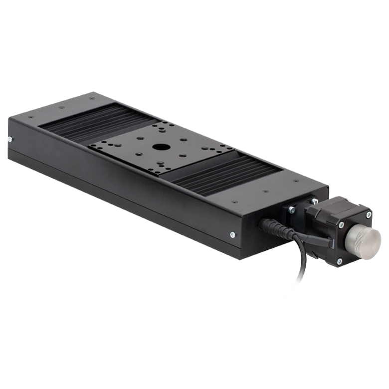
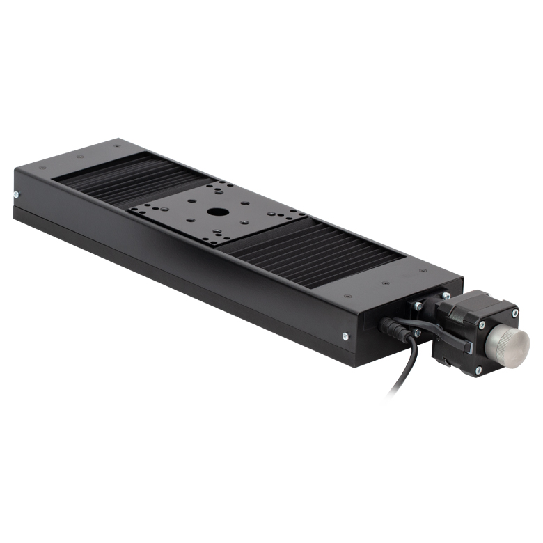
- Single-Axis and Three-Axis Versions
- Z912B DC Servo Actuator Provides 12 mm (0.47") Travel per Axis
- Includes Two Alignment Pins per One-Axis Stage or Four Alignment Pins for the Three-Axis Stage for Stacking and Mounting Accessories
- Controller and Power Supply Sold Separately
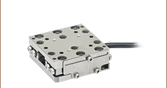
Thorlabs' MT1-Z9 (MT1/M-Z9) Single-Axis and MT3-Z9 (MT3/M-Z9) Three-Axis Motorized Translation Stages provide linear, orthogonal motion in one or three dimensions. Seven 1/4"-20 (M6) tapped holes on the mounting surface allow easy integration with a wide variety of common optomechanical setups. The stages feature hardened steel linear bearings for precision motion and long life.
The MT1-Z9 stage is designed for single-axis translation. For applications requiring XY motion, simply purchase two MT1-Z9 stages and stack them using the provided alignment pins to ensure orthogonality. If XYZ motion is desired, then we recommend the MT3-Z9 stage. In addition to alignment pins for all three axes, the MT3-Z9 (MT3/M-Z9) includes an MT401 Base Plate and an MT402 Right-Angle Bracket. For more details on these accessories, please read below.
Each axis requires a standalone controller unit and power supply to operate. For this purpose, we recommend our KDC101 K-Cube™ Motor Controller, which is described in more detail below.
The motor cable that is built into the Z912B actuator is 485 mm (1.59 ft) long. If more length is required for your application, we recommend our PAA632 Extension Cable, which provides an additional 2.5 m (8.20 ft). It is sold at the bottom of this page.

 Zoom
Zoom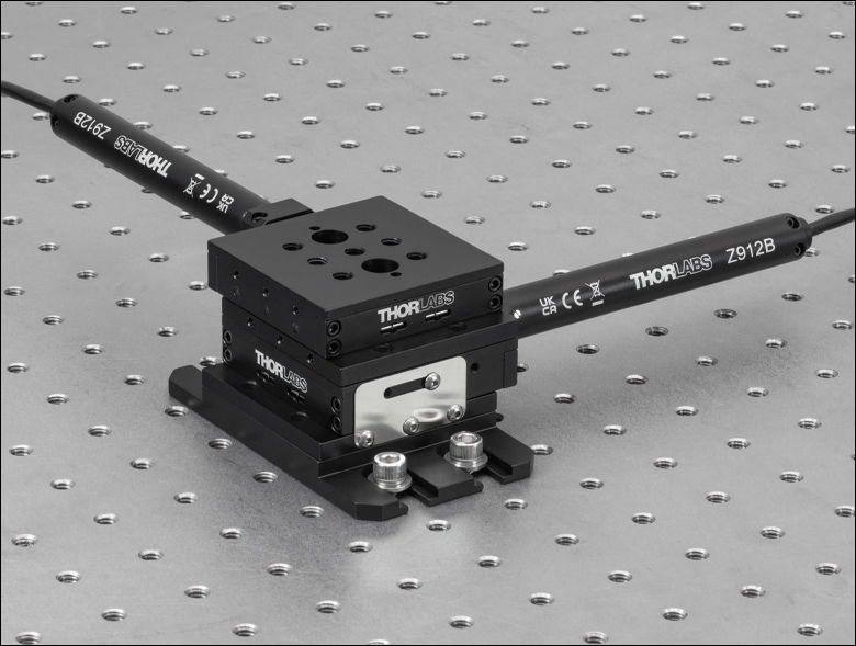
Click to Enlarge
Two Stacked MT1-Z9 Single-Axis Stages Mounted to a Breadboard via an MT401 Base Plate
- Mount an MT1-Z9 (MT1/M-Z9) Single-Axis Stage to a Breadboard or Optical Table
- Four 1/4"-20 (M6) Mounting Holes
- Alignment Holes Ensure Parallelism
- Contains Four 1/4" (M6) Counterbored Slots
The MT401(/M) Base Plate is ideal for securing the stages sold above to an optical table or breadboard when counterbores in the middle of the stages are obstructed. This base plate provides mounting flanges with 1" (25 mm) centers. For a single-axis stage, the base plate allows an attached stage to be mounted on a breadboard without having to disassemble a setup that already exists on the moving platform in order to access the mounting holes.
Two 1/4"-20 cap screws (3/16” hex) or two M6 cap screws (5 mm hex) are included with the MT401 imperial or MT401/M metric base plate, respectively, for mounting an MT stage. The two alignment pins included with the MT1(/M)-Z9 stage fit into the stage and base plate, ensuring that the translation axis is parallel to the plate.

 Zoom
Zoom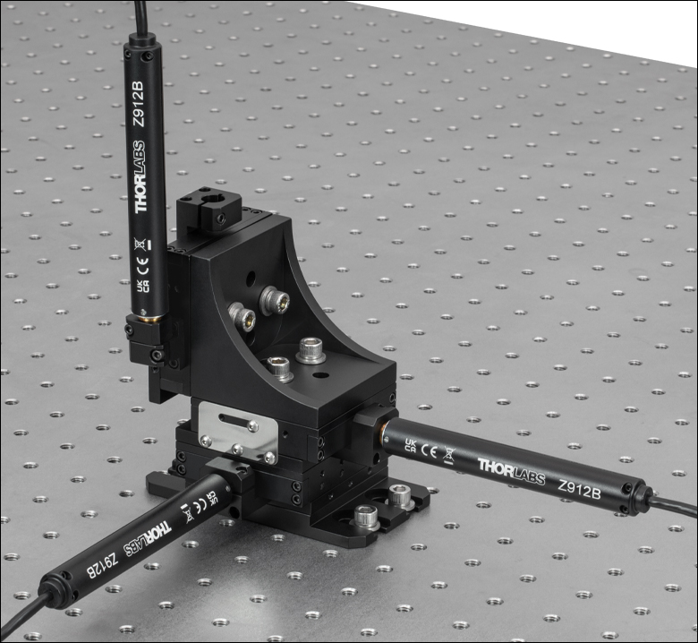
Click to Enlarge
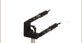
Three MT1-Z9 Single-Axis Stages Mounted into an XYZ Configuration via an MT402 Right-Angle Bracket
- Vertically Mount an MT1-Z9 (MT1/M-Z9) Translation Stage
- Designed for XY, XZ, or XYZ Configurations
- Alignment Holes Ensure Orthogonality
- Includes All Necessary Mounting Hardware for Imperial and Metric Setups
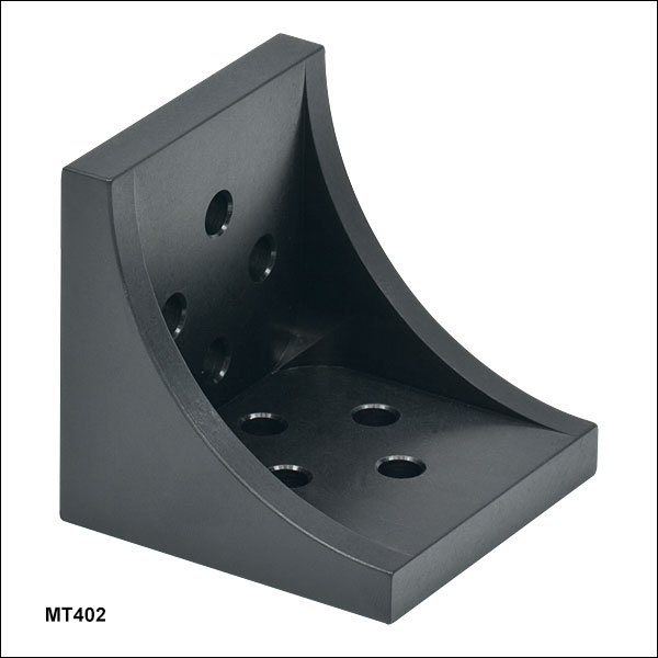
The MT402 Right-Angle Bracket orients an MT1-Z9 (MT1/M-Z9) Single-Axis Stage in the vertical plane and allows for the construction of XY, XZ, or XYZ arrangements. This angle bracket is pre-drilled and includes four 1/4"-20 screws (3/16" hex) and four M6 screws (5 mm hex) for compatibility with both imperial and metric setups. Balldrivers and hex keys are sold separately here. This bracket is included with the purchase of an MT3-Z9 (MT3/M-Z9) Three-Axis Stage.
To begin the assembly process, insert the two alignment pins provided with the MT1-Z9 stage into the stage's alignment holes. Then position the bracket's alignment holes above the pins. The bracket can be fastened down using two 1/4"-20 (M6) cap screws. At this point, the bracket's vertical mounting surface will accommodate a stage that is attached horizontally (for XY configurations) or vertically (for XZ or XYZ configurations). For details, please see the XYZ Assembly tab on the MT1 Manual Translation Stages page; this page shows different actuators, but the assembly process is otherwise identical.

 Zoom
Zoom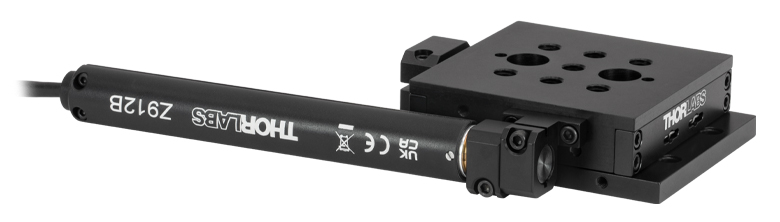
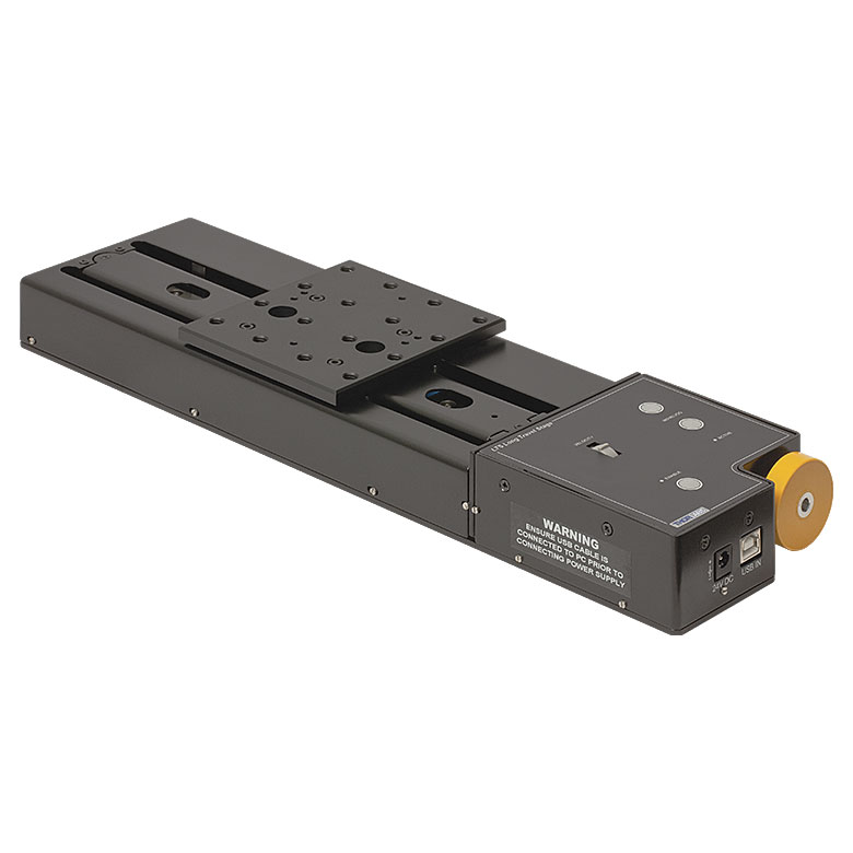
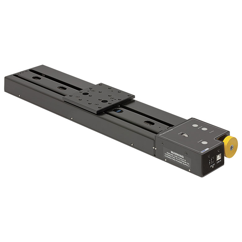
Click to Enlarge
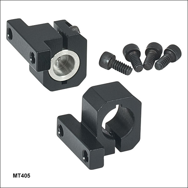
An MT405 adapter is used to reduce to total length of the MT1-Z9 stage.
- Reduce the Total Length of the MT1-Z9 (MT1/M-Z9) Stage
- Four 4-40 Mounting Screws Included
The MT405 Side-Mounted Actuator Adapter allows the actuator to be repositioned from the rear of the stage to the side, as shown in the image on the right. The adapter attaches to the side of the stage that does not contain the locking screw and plate. This reduces the overall length of the stage assembly by 1.2" (30 mm), while increasing the width by 0.71" (18 mm).

 Zoom
Zoom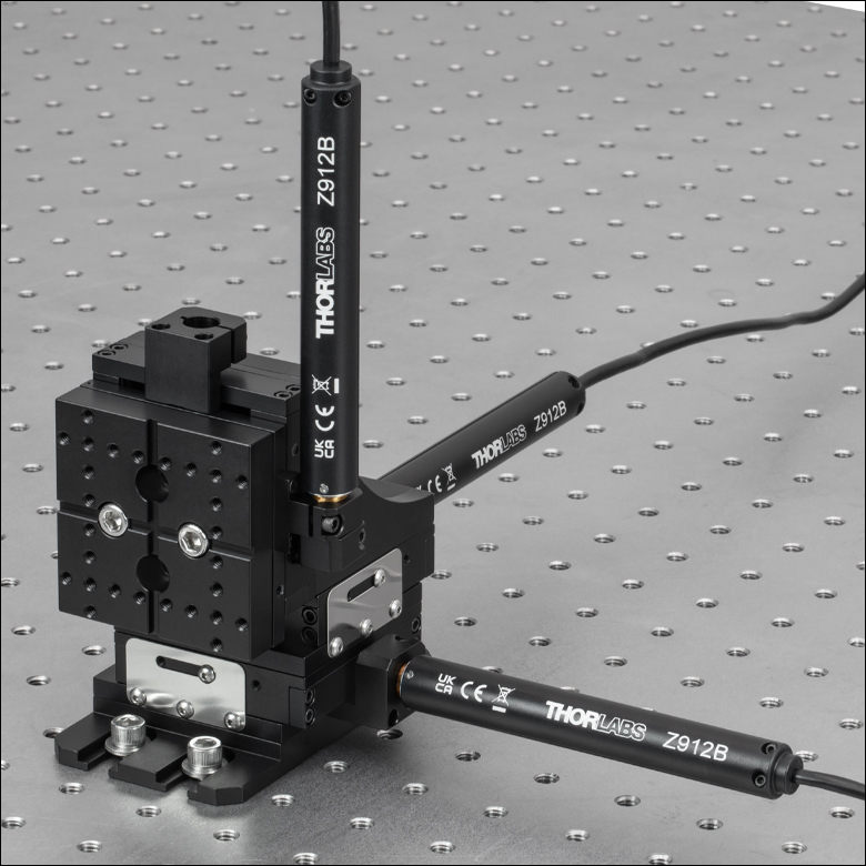
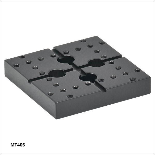
Click to Enlarge
Vertically Mounted MT406 Flexure Stage Accessories Plate
- Use Flexure Stage Accessories with an MT1-Z9 Stage
- Includes Two Alignment Pins that Ensure Parallelism
- Two 1/4"-20 (M6) Cap Screws Provided
The MT406(/M) Flexure Stage Accessories Adapter Plate is compatible with our full range of flexure stage accessories and is ideal for creating basic fiber coupling solutions. It fastens directly to the top of the MT1-Z9 (MT1/M-Z9) stage with two 1/4"-20 (M6) cap screws and contains twenty-eight 6-32 (M3) taps.

 Zoom
Zoom Click to Enlarge
KCH601 USB Controller Hub (Sold Separately) with Installed K-Cube and T-Cube™ Modules (T-Cubes Require the KAP101 Adapter)
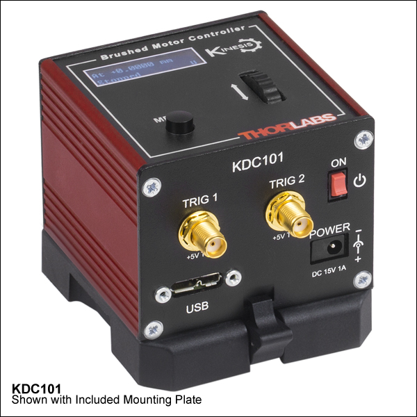
- Front Panel Velocity Wheel and Digital Display for Controlling Motorized Stages or Actuators
- Two Bidirectional Trigger Ports to Read or Control External Equipment
- Interfaces with Computer Using Included USB Cable
- Fully Compatible with Kinesis® or APT™ Software Packages
- Compact Footprint: 60.0 mm x 60.0 mm x 49.2 mm (2.42" x 2.42" x 1.94")
- Power Supply Not Included (See Below)
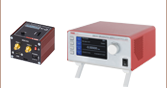
Thorlabs' KDC101 K-Cube Brushed DC Motor Controller provides local and computerized control of a single motor axis. It features a top-mounted control panel with a velocity wheel that supports four-speed bidirectional control with forward and reverse jogging as well as position presets. A backlit digital display is also included that can have the backlit dimmed or turned off using the top-panel menu options. The front of the unit contains two bidirectional trigger ports that can be used to read a 5 V external logic signal or output a 5 V logic signal to control external equipment. Each port can be independently configured.
The unit is fully compatible with our new Kinesis software package and our legacy APT control software. Please see the Motion Control Software tab for more information.
Please note that this controller does not ship with a power supply. Compatible power supplies are listed below. Additional information can be found on the main KDC101 DC Servo Motor Controller page.

 Zoom
Zoom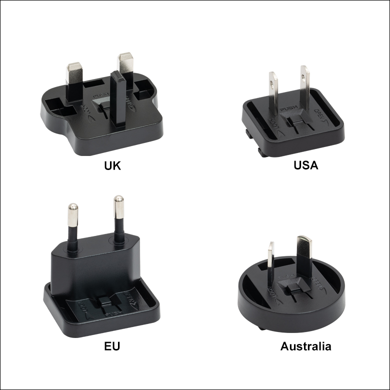
Click for Details
Each KPS201 power supply includes one region-specific adapter, which can be selected upon checkout.
Click to Enlarge
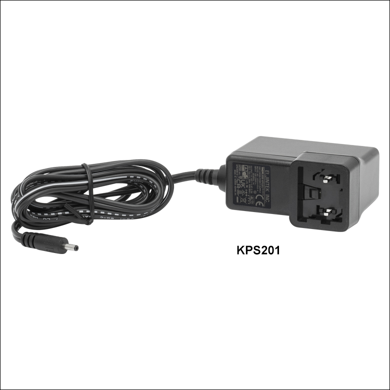
The KPS201 Power Supply Unit
- Individual Power Supply
- KPS201: For K-Cubes™ or T-Cubes™ with 3.5 mm Jacks
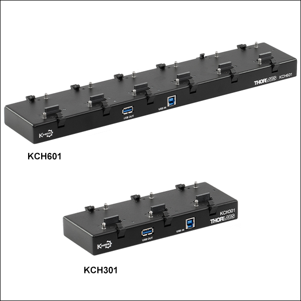
- USB Controller Hubs Provide Power and Communications
- KCH301: For up to Three K-Cubes or T-Cubes
- KCH601: For up to Six K-Cubes or T-Cubes
The KPS201 power supply outputs +15 VDC at up to 2.66 A and can power a single K-Cube or T-Cube with a 3.5 mm jack. It plugs into a standard wall outlet.
The KCH301 and KCH601 USB Controller Hubs each consist of two parts: the hub, which can support up to three (KCH301) or six (KCH601) K-Cubes or T-Cubes, and a power supply that plugs into a standard wall outlet. The hub draws a maximum current of 10 A; please verify that the cubes being used do not require a total current of more than 10 A. In addition, the hub provides USB connectivity to any docked K-Cube or T-Cube through a single USB connection.
For more information on the USB Controller Hubs, see the full web presentation.

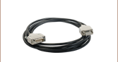
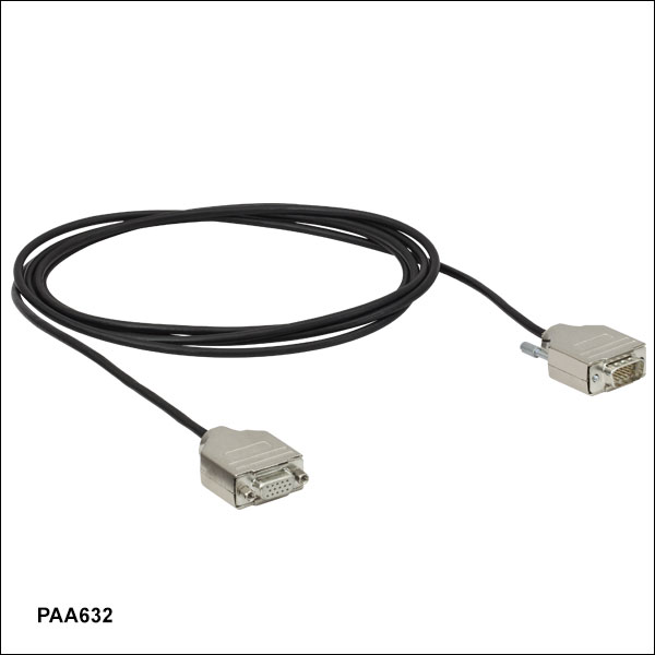 Zoom
ZoomThe PAA632 Extension Cable provides an additional 2.5 m (8.20 ft) of cable length for the 15-pin D-type connectors used throughout our motorized actuator selection. The male end connects to the controller, while the female end connects to the motor.