 Products Home / Motorized Stages / Motorized Linear Stages / Motorized 50 mm (1.97") Linear Translation Stages / 50 mm Linear Translation Stage, Direct-Drive Brushless Servo Motor
50 mm Linear Translation Stage, Direct-Drive Brushless Servo Motor
- 50 mm Travel at Speeds Up to 500 mm/s
- Brushless DC Servo Motors
- Stackable in XY Configuration
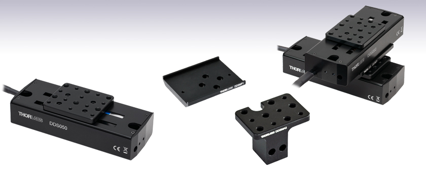
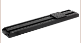
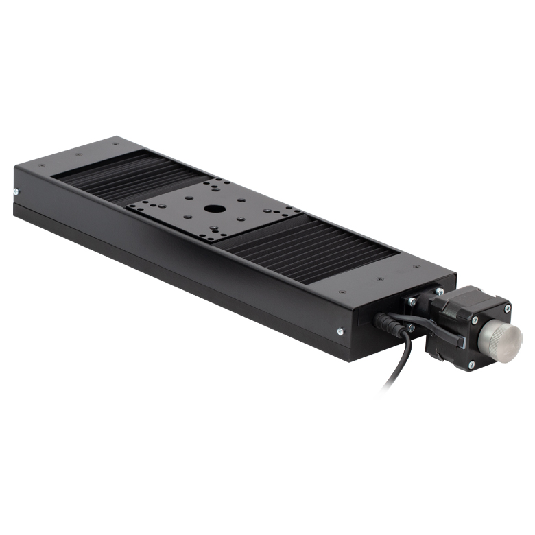
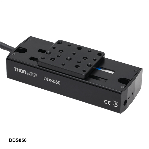
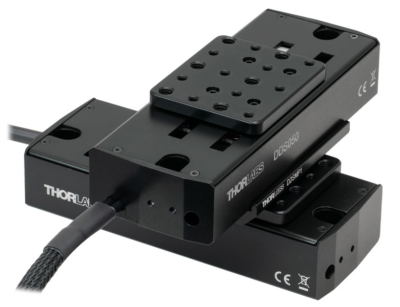
DDS050
50 mm (1.97") Servo Motor
Translation Stage
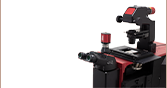
Application Idea
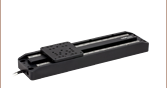
Two DDS050 Stages in XY Configuration,
Using an DDSMP1 Adapter Plate
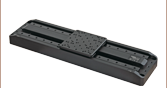
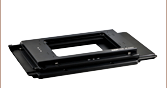
DDSMP1
XY Adapter Plate
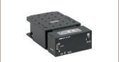
DDSMA2
End Mounting Adapter


Please Wait
| Item # | DDS050(/M) |
|---|---|
| Travel Range | 50 mm (1.97") |
| Speed (Max)a | 500 mm/s |
| Acceleration (Max) | 5000 mm/s2 |
| Bidirectional Repeatabilityb | ±1.5 µm |
| Straightness/Flatness | ±5.0 µm |
| Horizontal Load Capacity (Max) | 0.9 kg (1.98 lbs) |
| Min Incremental Movementc | 5.0 µm |
| Absolute On-Axis Accuracy | ±6.5 µm |
| Actuator Type | Brushless DC Servo Motor |
| Dimensions (L x W x H) | 145.0 mm x 57.0 mm x 35.0 mm (5.71" x 2.24" x 1.38") |
Features
- 50 mm Travel Range
- Integrated, Brushless DC Linear Servo Motor Actuators
- Linear Optical Encoders
- High-Quality, Precision-Engineered Linear Bearings
- 0.9 kg Horizontal Load Capacity
- Stackable in XY Configuration
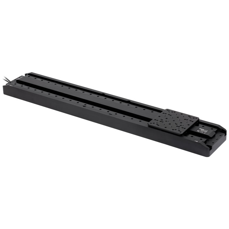
Thorlabs' DDS050(/M) low-profile, direct-drive stage provides 50 mm of travel with ±6.5 µm on-axis accuracy and a maximum speed of 500 mm/s. The stage is ideal for applications that require high speeds and high positioning accuracy, including automated alignment, surface inspection, mapping, and probing.
An innovative, low-profile design with integrated, brushless linear motors eliminates the external housings that create mechanical clash points and impede access to the moving platform. The brushless DC servo motor removes the need for a lead screw, eliminating backlash, and internal flexible ducting ensures cables cannot become trapped as the mechanism moves. A precision-grooved linear bearing provides superior rigidity and linearity with excellent on-axis accuracy. This backlash-free operation coupled with high-resolution, closed-loop optical feedback ensures a minimal bidirectional repeatability of ±1.5 μm.
Click to Enlarge
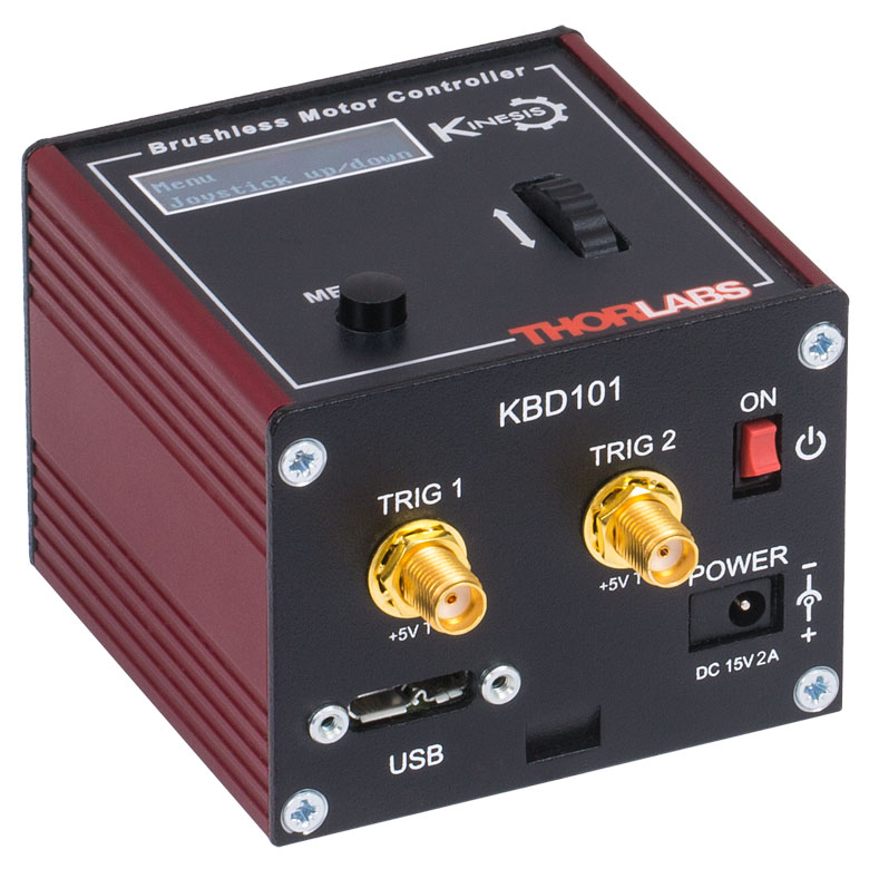
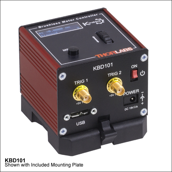
Figure 1.1 The KBD101 K-Cube Brushless DC Servo Motor Controller (sold separately below) is required to drive these stages.
| Motorized Linear Translation Stages | |
|---|---|
| 12 mm | Standard |
| 25 mm | Compact |
| Standard | |
| TravelMax | |
| 50 mm | Compact |
| Direct-Drive Servo | |
| TravelMax | |
| Long Travel: 100 mm to 300 mm | |
Controller
The required controller for the DDS050(/M) direct-drive, linear translation stage is the KBD101
K-Cube® Brushless DC Motor Controller. This controller provides a user-configurable, S-curve acceleration/deceleration profile that enables fast, smooth positioning without vibration or shock. See below for a brief overview, or click here to view the full presentation for these Brushless DC Motor Controllers.
Mounting Adapters
For dual-axis applications, two stages can be bolted together in an XY configuration by using the DDSMP1 XY adapter plate as shown above. Note that these stages are not suitable for operation in a vertical (Z-axis) orientation. Please contact Tech Support for more details.
Adapter brackets are also available that allow optomechanical components to be mounted close to the linear travel of the stage in applications such as a delay line. Please see below for more details.
Please Note: Magnetic components should not be mounted to the stage platform. Magnets prevent proper homing and can affect the accuracy of the stage's encoder even after the magnetic component has been removed. When no power is applied, the platform of the stage has very little inertia and is virtually free running. This may make the stage unsuitable for applications where the stage's platform needs to remain in a set position when power is off.
| Item # | DDS050(/M) |
|---|---|
| Travel Range | 50 mm (1.97") |
| Speed (Max)a | 500 mm/s |
| Speed (Min)b | 70 nm/s |
| Acceleration (Max) | 5000 mm/s2 |
| Acceleration (Max) at 0.9 kg Load | 500 mm/s2 |
| Resolution | 500 nm |
| Bidirectional Repeatabilityc | ±1.5 µm |
| Backlash | N/A (No Leadscrew) |
| Min Incremental Movementd | 5.0 µm |
| Horizontal Load Capacity (Max) | 0.9 kg (1.98 lbs) |
| Absolute On-Axis Accuracy | ±6.5 µm |
| Straightness/Flatness | ±5.0 µm |
| Pitch | ±175 µrad |
| Yaw | ±175 µrad |
| Continuous Motor Forcee | 0.8 N |
| Peak Motor Force (5 s)f | 2.0 N |
| Bearing Type | High Rigidity Recirculating Precision Linear Bearing |
| Limit Switches | Magnetic Sensor at Each End of Stage |
| Operating Temperature Range | 5 to 40 °C (41 to 104 °F) |
| Motor Type | Brushless DC Linear Motor |
| Cable Length | 1 m (3.3') |
| Dimensions (L x W x H) | 145.0 mm x 57.0 mm x 35.0 mm (5.71" x 2.24" x 1.38") |
| Weight (with Cables) | 0.60 kg (1.3 lbs) |
Motor Control Connector
D-Type Male
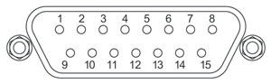
| Pin | Description | Pin | Description |
|---|---|---|---|
| 1 | Quadrature A- | 9 | Ground |
| 2 | Quadrature A+ | 10 | Motor Phase C |
| 3 | Quadrature B+ | 11 | Motor Phase A |
| 4 | Quadrature B- | 12 | Motor Phase B |
| 5 | Encoder Index I- | 13 | +5 V |
| 6 | Encoder Index I+ | 14 | Ground |
| 7 | Negative Limit | 15 | Stage ID |
| 8 | Positive Limit |
Software
Kinesis Version 1.14.56
XA Version 1.3.0
The Kinesis and XA Software Packages, which include a GUI for control of Thorlabs' motion controllers.
Also Available:
- Firmware Update Utilities
- Communications Protocol
Figure 789A Kinesis GUI Screen
Thorlabs offers two platforms to drive our wide range of motion controllers: our XA software package and our Kinesis software package, which is being phased out. The Kinesis software supports most of Thorlabs' motion control products. The XA software is an improved platform for developers that currently supports some of our most popular motion control products (see the full list of supported products here). The software is undergoing continuous, intensive development and will eventually add support for our entire line of motion control products. The XA software application will be fully supported through the year 2040.
Kinesis Motion Control Software
The Kinesis software features .NET controls which can be used by 3rd party developers working in the latest C#, Visual Basic, LabVIEW™, or any .NET compatible languages to create custom applications. Low-level DLL libraries are included for applications not expected to use the .NET framework. A Central Sequence Manager supports integration and synchronization of all Thorlabs motion control hardware.
By providing a common software platform, Thorlabs has ensured that users can easily mix and match any of the Kinesis controllers in a single application, while only having to learn a single set of software tools. In this way, it is perfectly feasible to combine any of the controllers from single-axis to multi-axis systems and control all from a single, PC-based unified software interface.
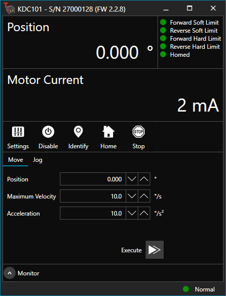
Click to Enlarge
Figure 789B XA GUI for KDC101 Brushed DC Servo Controller
The software package allows two methods of usage: graphical user interface (GUI) utilities for direct interaction with and control of the controllers out of the box, and a set of programming interfaces that allow custom-integrated positioning and alignment solutions to be easily programmed in the development language of choice.
XA Motion Control Software: Improved Platform for Developers
Designed from the ground up to be straightforward to understand, XA provides a thread-safe and language-paradigm-agnostic set of application programming interfaces in C, C++, and C#/.NET with language wrappers available to allow for easy integration into your native, .NET language, Python, or LabVIEW applications. This enables the same functionality as mentioned for the Kinesis software development kit (SDK) while providing a more streamlined toolkit for developers. Coupled with the included developer guides and code examples in the SDK, this software is tailored toward users interested in creating complex, customized applications and interfaces. Full API documentation is provided for the native C library, and the .NET wrapper documentation is currently under development. Please contact Tech Support for more details on using the .NET wrapper.
XA also features a comparable GUI to Kinesis while adding improvements to the user experience, like the ability to save device states and a more consistent interface across devices of different types. In addition, further improvements are planned as XA will be fully supported through the year 2040, whereas the Kinesis software is being phased out. The current version of the XA software can only drive select Thorlabs motion controllers. However, the software is undergoing continuous, intensive development and will eventually add support for our entire line of motion control products. Information on software compatibility can be found in the XA User Guide, and additional details about the software, including a list of compatible devices, can be found here.
| Posted Comments: | |
Mattia Ronch
(posted 2021-07-21 13:23:33.08) Dear Madam/Sir,
would you be so kind to send me the 3D cad of this product?
Thanks for your attention.
Best regards,
MR DJayasuriya
(posted 2021-07-22 03:28:37.0) Thank you for your inquiry. You would be able to find this on our website :https://www.thorlabs.de/thorproduct.cfm?partnumber=DDS050/M ('Drawings and Documents'' table on he right hand side, you can download the 'Solidworks' file) tillsten
(posted 2018-11-12 21:20:09.777) It is possible to use the stage vertically? AManickavasagam
(posted 2018-11-14 06:51:56.0) Response from Arunthathi at Thorlabs - Thanks for your query. These do not have enough torque to be used in the Z configuration. You probably need a stage with a lead screw that provides sufficient torque such as our LNR50 or MTS50/M-Z8. linahacker91
(posted 2018-09-03 17:42:07.397) Hello, I'm looking for a linear 50 mm motorized stage with high position accuracy (Travel speed is not important and the load will be very low) and the positioning should be repeatable. I should probably choose a stepper motor, right? Or is there a cheaper option? Thank you for your help! AManickavasagam
(posted 2018-09-06 05:43:28.0) Response from Arunthathi @ Thorlabs: Thanks for your query. Yes you are correct comparatively for better repeatability, it will be best to use a stepper motor actuator - stage such as the LNR50S which has 0.5 µm Bidirectional repeatability. However, for even more precise positioning we offer LNR50SE which has an inbuilt encoder that works in closed loop with the actuator to maintain positional accuracy. tim.may
(posted 2017-11-21 14:48:57.217) Hi, occasionally the ddsm50 will not 'home', gives 'Motor Error Detected (Value-position Error(0))' I end up closing the software and shutting off the kbd101 controller sn 28000398 and restarting, sometime it comes back ok, sometimes takes several cycles of the power. What's up with it?
the load is 0.48 kg, but even with load removed still fails to home. Thanks for any help.
Tim bhallewell
(posted 2017-12-01 09:12:28.0) Response from Ben at Thorlabs: Thank you for contacting us. This
Position Error message is posted when the achieved position is significantly different to the expected position. Typically this can be caused by running too fast with the given load. If the problem persists, it is suggested to Home the device at a lower velocity.
I will contact you directly to troubleshoot the issue. tim.may
(posted 2017-10-16 13:11:26.45) HI again, I asked about loading at .59# but realise i also have a plate mounted that is 0.48# so the total is >1 kg, beyond the 0.9 limit.
my bad, trying another plate
thanks tim bwood
(posted 2017-10-17 06:24:02.0) Response from Ben at Thorlabs: Thank you for your feedback. You should try and limit the load on the stage to below 1kg. However, you may have to change the PID loop settings to suit the load on the stage anyway. You can find more details on this in section 6.3.4 of the KBD101 manual. tim.may
(posted 2017-10-14 12:47:37.067) I have a single stage with load of 1.24# or .56 kg and the stage oscillates on positioning away from home. can some parameter in the loop be adjusted to stop the oscillation? I saw comment here that state 0.9kg is possible, but couldn't find that on spec page.
Thanks bwood
(posted 2017-10-17 06:33:26.0) Please find my responce above. d.baresch
(posted 2017-07-24 17:47:57.79) The maximum specified horizontal load is 0.9kg. Does this mean that with 2 DDSM50 mounted in XY configuration the only useful load left is 0.3kg (given 1 DDSM50 weighs 0.6kg)? bwood
(posted 2017-07-25 10:56:41.0) Response from Ben at Thorlabs: Thank you for your feedback. This is correct, according to the specifications the maximum load of an XY DDSM50 assembly will be 0.3 kg. If you need a high load, we would recommend the MTS50 and LNR50. zali023
(posted 2016-08-21 15:14:16.467) Hi
I am currently using a 50 mm (1.97") Compact Motorized Translation Stage, but its velocity stability at ±0.25 mm/sec is too high my application, could you please advise me on the velocity stability for this instrument? bhallewell
(posted 2016-08-22 11:20:52.0) Response from Ben at Thorlabs: Thank you for your feedback. The velocity ripple would be dependent upon the PID control loop settings, the load applied to the stage & also the velocity that you are moving to & from. Generally moving to a lower velocity, you will find a higher percentage ripple however at a reduced deviation. I will contact you to obtain details of your setup to see if this can be optimised. vopop
(posted 2016-06-09 15:03:32.63) I want to use DDSM50 with '30 mm Cubes with Premounted Turning Mirrors' in vertically aligned state. I saw there written we can not use in vertically aligned state. So, I wonder whether this means just due to there is no stopping force or its due to malfunctioning. besembeson
(posted 2016-06-09 09:41:15.0) Response from Bweh at Thorlabs USA: Yes it is due to no stopping force. When no power is applied, the stage has very little inertia so the platform will roll down under its weight and mounted components. cbrideau
(posted 2015-09-23 18:34:29.417) What is the typical Angular Deviation for this mount? bhallewell
(posted 2015-09-30 06:49:25.0) Response from Ben at Thorlabs: Thank you for your question here. The spec that you are looking for would be synonymous with the Pitch & Yaw Run-out, which is ±175 µrad. This detail can be located in the ‘Specs’ tab. |
Motorized Linear Translation Stages
Thorlabs' motorized linear translation stages are offered in a range of maximum travel distances, from a stage with 20 µm of piezo translation to our 600 mm direct drive stage. Many of these stages can be assembled in multi-axis configurations, providing XY or XYZ translation. For fiber coupling applications, please see our multi-axis stages, which offer finer adjustment than our standard motorized translation stages. In addition to motorized linear translation stages, we offer motorized rotation stages and goniometers. We also offer manual translation stages.
Piezo Stages
These stages incorporate piezoelectric elements in a variety of drive mechanisms. ORIC® stages incorporate piezo inertia drives that use "stick-slip" friction properties to obtain extended travel ranges. Our Nanoflex™ translation stages use standard piezo chips along with manual actuators. Elliptec® stages use resonant piezo motors to push and pull the moving platform through resonant elliptical motion. Our LPS710E z-axis stage features a mechanically amplified piezo design and includes a matched controller.
| Piezoelectric Stages | ||||||
|---|---|---|---|---|---|---|
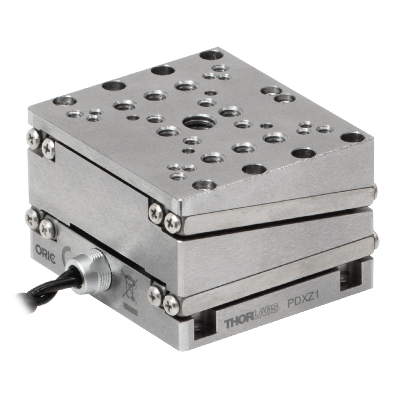
| Product Family | ORIC® PDXZ1 Closed-Loop 4.5 mm Vertical Stage |
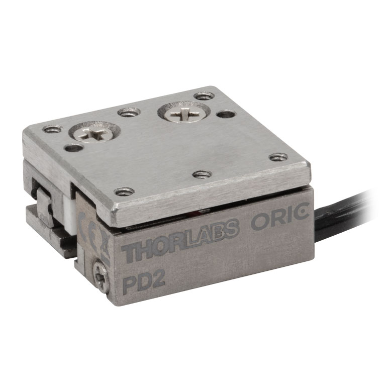
ORIC® PD2 Open-Loop 5 mm Stage |
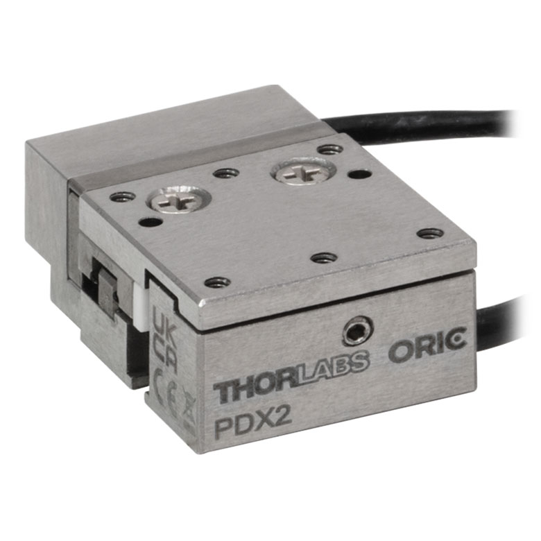
ORIC® PDX2 Closed-Loop 5 mm Stage |
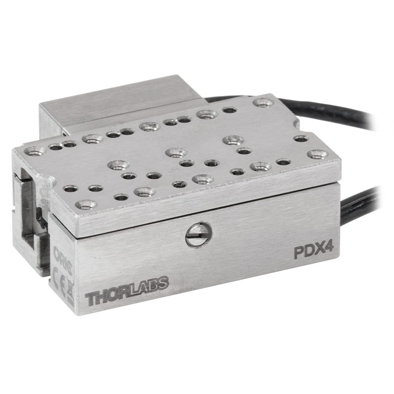
ORIC® PDX4 Closed-Loop 12 mm Stage |
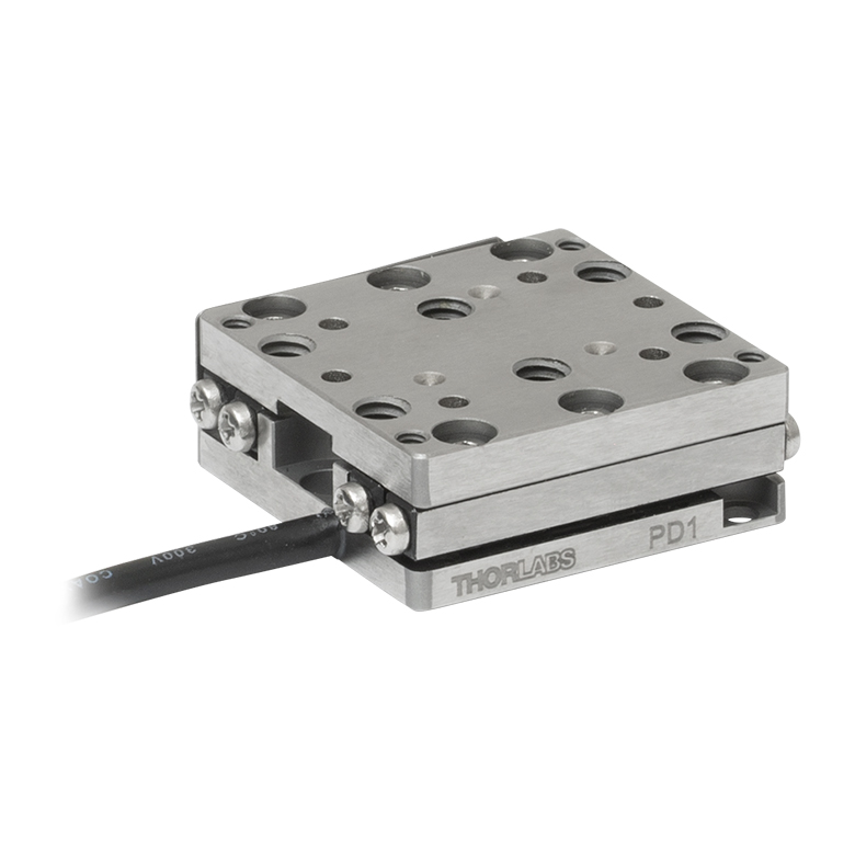
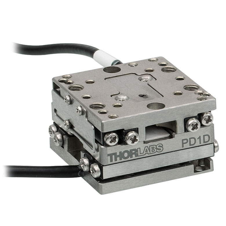
ORIC® PD1 Open-Loop 20 mm Stage |
ORIC® PD1D Open-Loop 20 mm Monolithic XY Stage |
| Click Photo to Enlarge |
 |
 |
 |
 |
 |
 |
| Travel | 4.5 mm | 5 mm | 12 mm | 20 mm | ||
| Speed | 1 mm/s (Typ.)a | 10 mm/s (Typ. Max)b | 8 mm/s (Typ.)c | 15 mm/s (Typ.)a,c | 3 mm/s (Typ. Max)d | |
| Drive Type | Piezoelectric Inertia Drive | |||||
| Possible Axis Configurations | Z | X, XY, XYZ | XY, XYZ | |||
| Mounting Surface Size |
45.0 mm x 42.0 mm | 13.0 mm x 13.0 mm | 13.0 mm x 23.0 mm | 30.0 mm x 30.0 mm | ||
| Additional Details | ||||||
| Piezoelectric Stages | ||||||
|---|---|---|---|---|---|---|
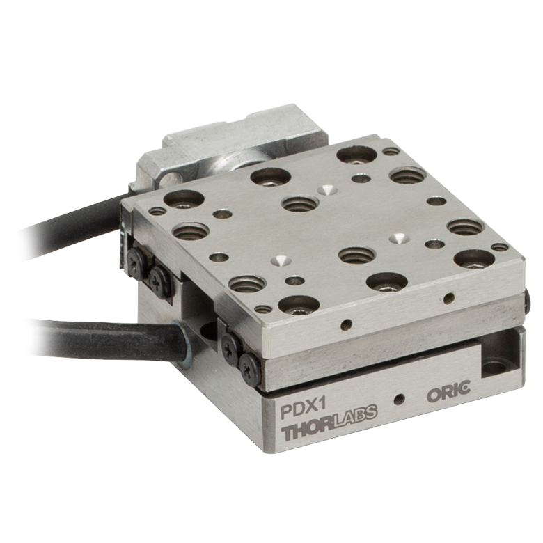
| Product Family | ORIC® PDX1 Closed-Loop 20 mm Stage |
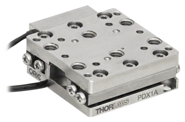
ORIC® PDX1A Closed-Loop 20 mm Stage Low-Profile |
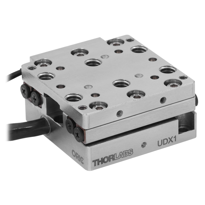
ORIC® UDX1 Ultrasonic Closed-Loop 20 mm Stage |
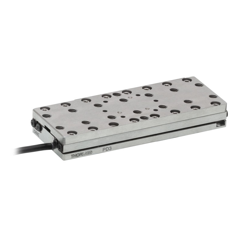
ORIC® PD3 Open-Loop 50 mm Stage |
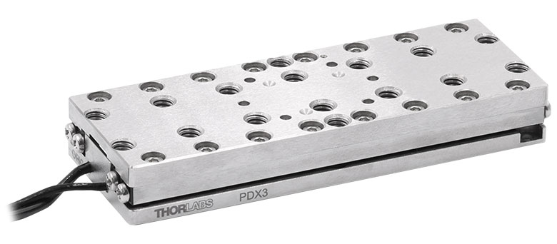
ORIC® PDX3 Closed-Loop 50 mm Stage |
|
| Click Photo to Enlarge |
 |
 |
 |
 |
 |
|
| Travel | 20 mm | 50 mm | ||||
| Speed | 20 mm/s (Typ. Max)a | 10 mm/s (Typ.)b | 100 mm/s (Typ. Max)c | 10 mm/sd | 10 mm/s (Typ. Max)b | |
| Drive Type | Piezoelectric Inertia Drive | Ultrasonic Piezoelectric Drive | Piezoelectric Inertia Drive | |||
| Possible Axis Configurations | X, XY, XYZ | |||||
| Mounting Surface Size |
30.0 mm x 30.0 mm | 80.0 mm x 30.0 mm | ||||
| Additional Details | ||||||
| Piezoelectric Stages | |||||||
|---|---|---|---|---|---|---|---|
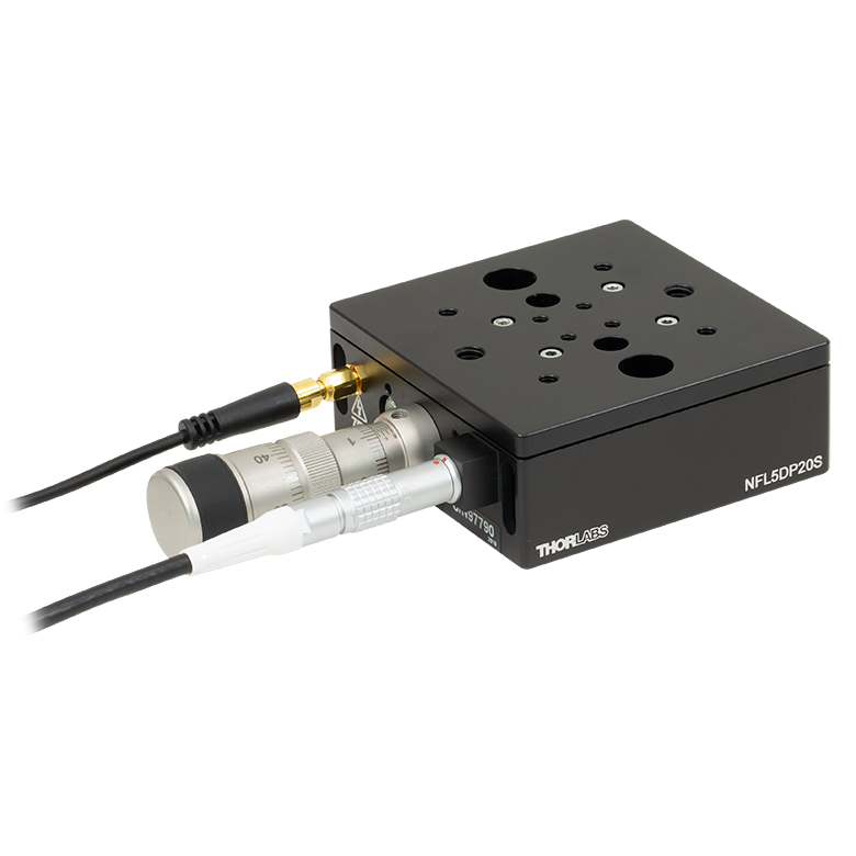
| Product Family | Nanoflex™ 20 µm Stage with 5 mm Actuator |
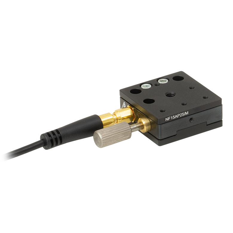
Nanoflex™ 25 µm Stage with 1.5 mm Actuator |
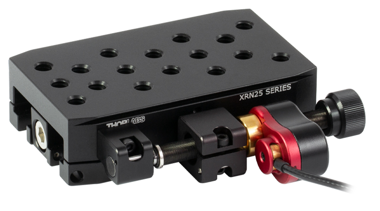
Compact Modular XRN25X 25 mm Stage |
Modular XR25X 25 mm Stage |
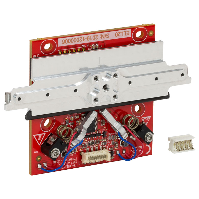
Elliptec® 28 mm Stage | Elliptec® 60 mm Stage | LPS710E 1.1 mm Vertical Stage |
| Click Photo to Enlarge |
 |
 |
 |
 |
 |
 |
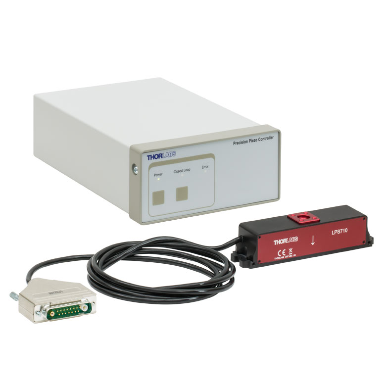 |
| Travel | 20 µm + 5 mm Manual | 25 µm + 1.5 mm Manual | 25 mm | 28 mm | 60.0 mm | 1.1 mm | |
| Maximum Velocity | - | ≤3.6 mm/mina | 180 mm/s | 90 mm/s | - | ||
| Drive Type | Piezo with Manual Actuator | Piezoelectric Inertia Drive | Resonant Piezoelectric Motor | Amplified Piezo | |||
| Possible Axis Configurations | X, XY, XYZ | X, XY, YZ, XZ, XYZ | X | Z | |||
| Mounting Surface Size | 75 mm x 75 mm | 30 mm x 30 mm | 85.0 mm x 50.7 mm | 110.0 mm x 75.7 mm | 15 mm x 15 mm | 21 mm x 21 mm | |
| Additional Details | |||||||
Stepper Motor Stages
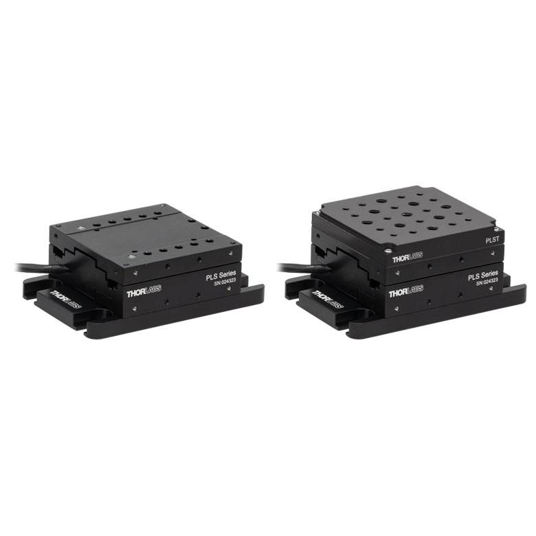
These translation stages feature removable or integrated stepper motors and long travel ranges up to 300 mm. Many of these stages either have integrated multi-axis capability (PLSXY) or can be assembled into multi-axis configurations (PLSX, LNR Series, NRT Series, and LTS Series stages). The MLJ150 stage also offers high load capacity vertical translation.
| Stepper Motor Stages | |||||
|---|---|---|---|---|---|
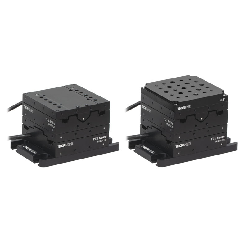
| Product Family | PLSX with and without PLST(/M) Top Plate 1" Stage |
PLSXY with and without PLST(/M) Top Plate 1" Stage |
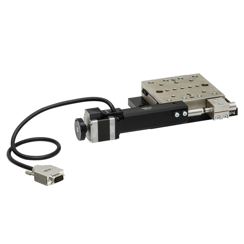
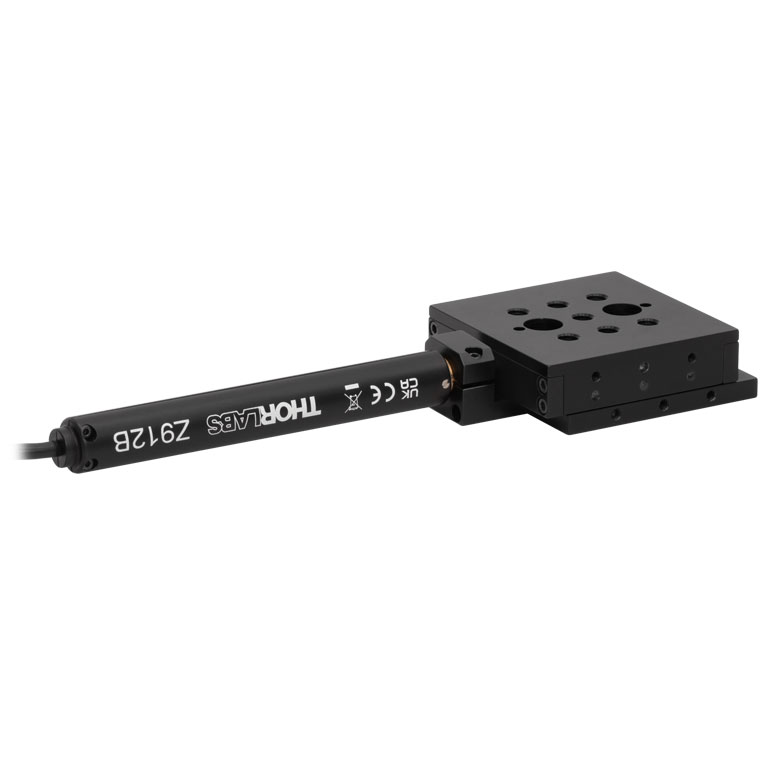
LNR Series 25 mm Stage |
LNR Series 50 mm Stage |
|
| Click Photo to Enlarge |
 |
 |
 |
 |
|
| Travel | 1" | 25 mm | 50 mm | ||
| Maximum Velocity | 7.0 mm/s | 2.0 mm/s | 50 mm/s | ||
| Possible Axis Configurations |
X, XY | X, XY, XYZ | X, XY, XYZ | ||
| Mounting Surface Size |
3" x 3" | 60 mm x 60 mm | 100 mm x 100 mm | ||
| Additional Details | |||||
| Stepper Motor Stages | |||||||
|---|---|---|---|---|---|---|---|
| Product Family | NRT Series 100 mm Stage |
NRT Series 150 mm Stage |
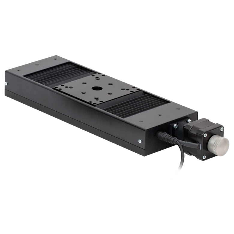
LTS Series 150 mm Stage |
LTS Series 300 mm Stage |
LTS Series 450 mm Stage |
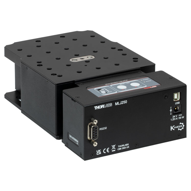
MLJ250 50 mm Vertical Stage |
|
| Click Photo to Enlarge |
 |
 |
 |
 |
 |
 |
|
| Travel | 100 mm | 150 mm | 150 mm | 300 mm | 400 mm | 50 mm | |
| Maximum Velocity | 30 mm/s | 50 mm/s | 3.0 mm/s | ||||
| Possible Axis Configurations |
X, XY, XYZ | X, XY, XYZ | X, XY | Z | |||
| Mounting Surface Size |
84 mm x 84 mm | 100 mm x 90 mm | 148 mm x 131 mm | ||||
| Additional Details | |||||||
DC Servo Motor Stages
Thorlabs offers linear translation stages with removable or integrated DC servo motors. These stages feature low profiles and many can be assembled in multi-axis configurations.
| DC Servo Motor Stages | ||||
|---|---|---|---|---|
| Product Family | MT Series 12 mm Stages |
PT Series 25 mm Stages |
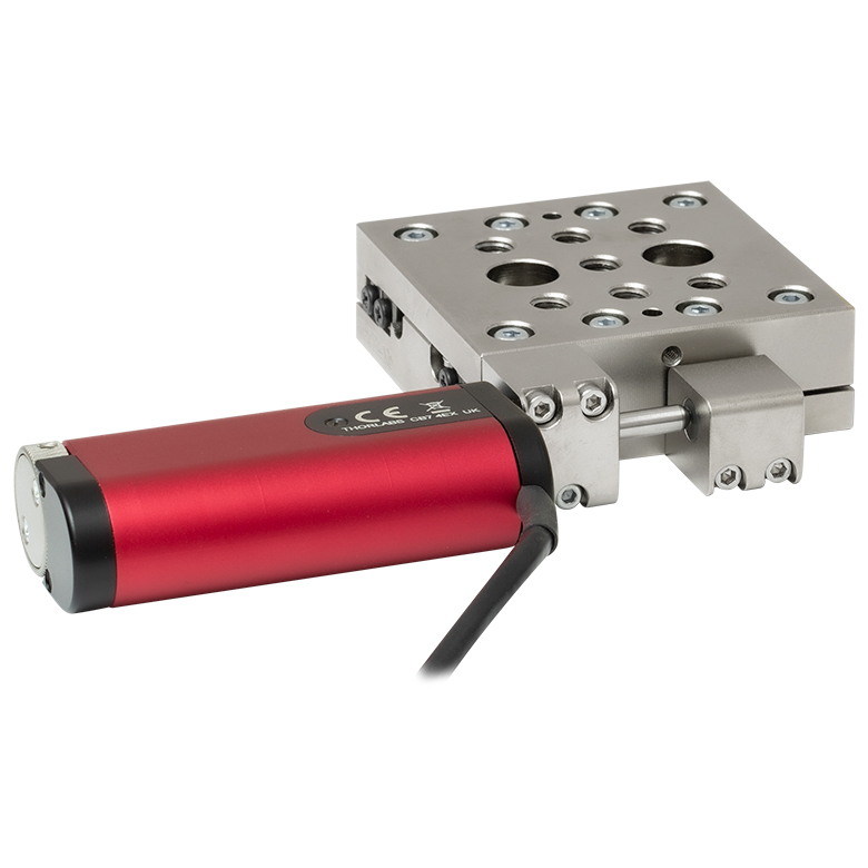
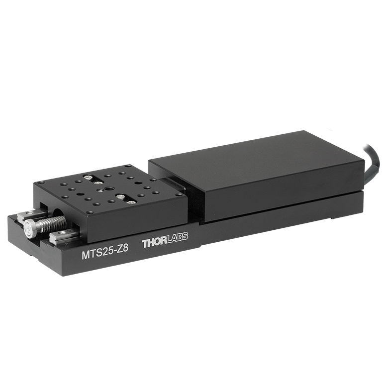
MTS Series 25 mm Stage |
MTS Series 50 mm Stage |
| Click Photo to Enlarge |
 |
 |
 |
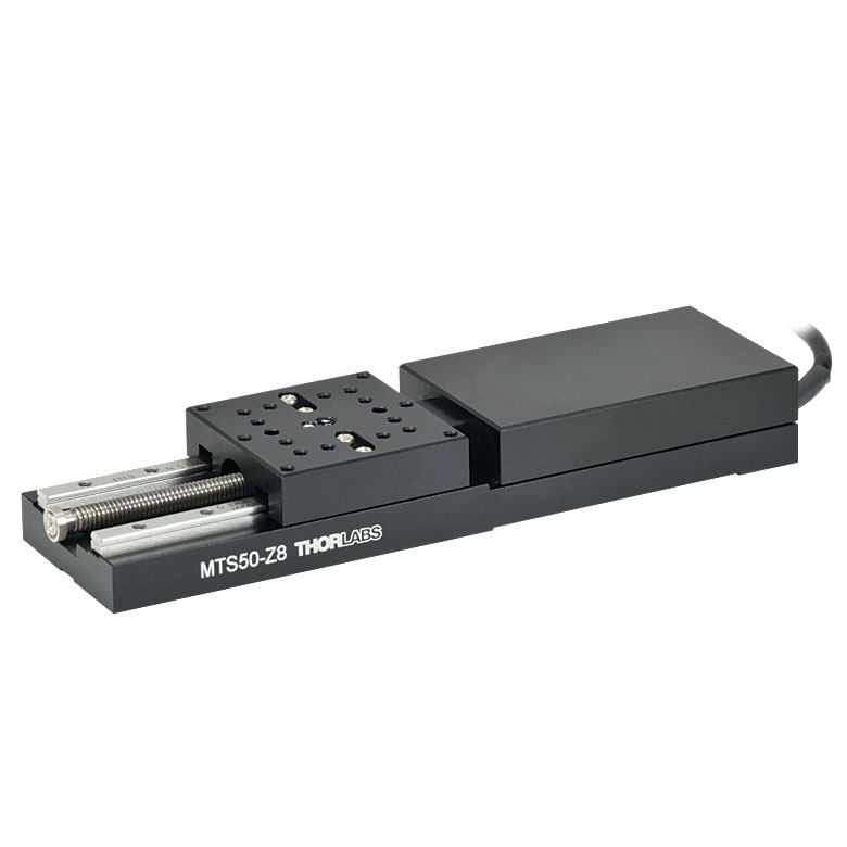 |
| Travel | 12 mm | 25 mm | 25 mm | 50 mm |
| Maximum Velocity | 2.6 mm/s | 2.4 mm/s | ||
| Possible Axis Configurations | X, XY, XYZ | X, XY, XYZ | ||
| Mounting Surface Size |
61 mm x 61 mm | 101.6 mm x 76.2 mm | 43 mm x 43 mm | |
| Additional Details | ||||
| DC Servo Motor Stages | ||||
|---|---|---|---|---|
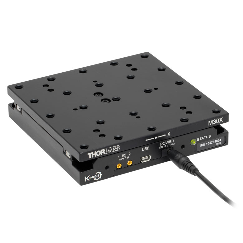
| Product Family | M30 Series 30 mm Stage |
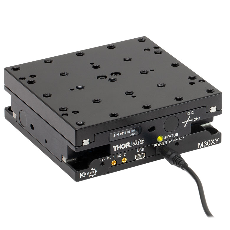
M30 Series 30 mm Monolithic XY Stage |
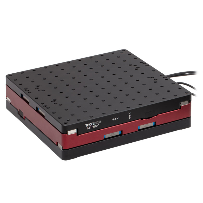
M150 Series 150 mm XY Stage |
KVS30 30 mm Vertical Stage |
| Click Photo to Enlarge |
 |
 |
 |
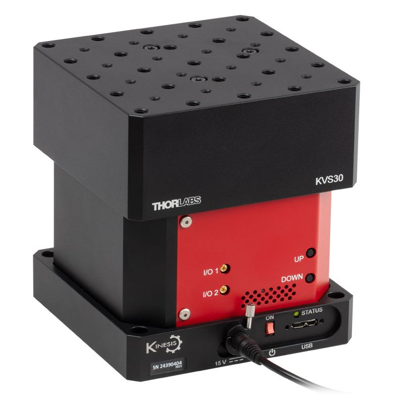 |
| Travel | 30 mm | 150 mm | 30 mm | |
| Maximum Velocity | 2.4 mm/s | X-Axis: 170 mm/s Y-Axis: 230 mm/s |
8.0 mm/s | |
| Possible Axis Configurations | X, Z | XY, XZ | XY | Z |
| Mounting Surface Size |
115 mm x 115 mm | 272.4 mm x 272.4 mm | 116.2 mm x 116.2 mm | |
| Additional Details | ||||
Direct Drive Stages
These low-profile stages feature integrated brushless DC servo motors for high speed translation with zero backlash. When no power is applied, the platforms of these stages have very little inertia and are virtually free running. Hence these stages may not be suitable for applications where the stage's platform needs to remain in a set position when the power is off. We do not recommend mounting these stages vertically.
| Direct Drive Stages | |||||
|---|---|---|---|---|---|
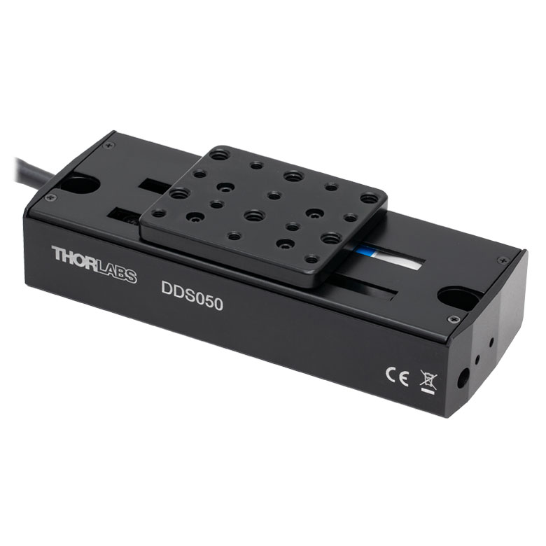
| Product Family | DDS Series 50 mm Stage |
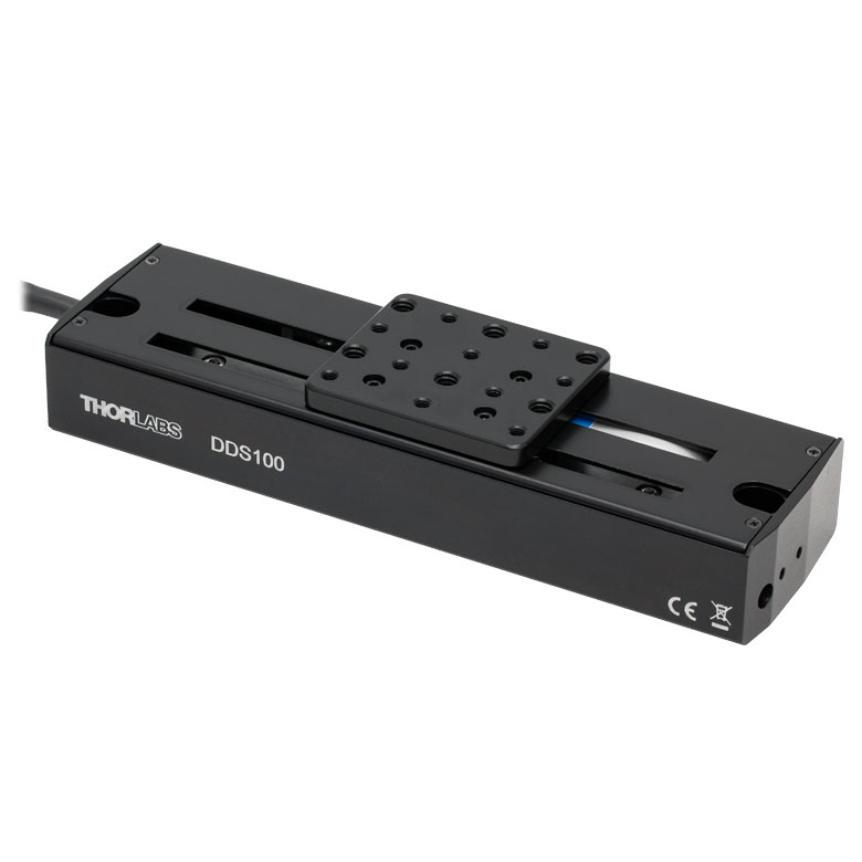
DDS Series 100 mm Stage |
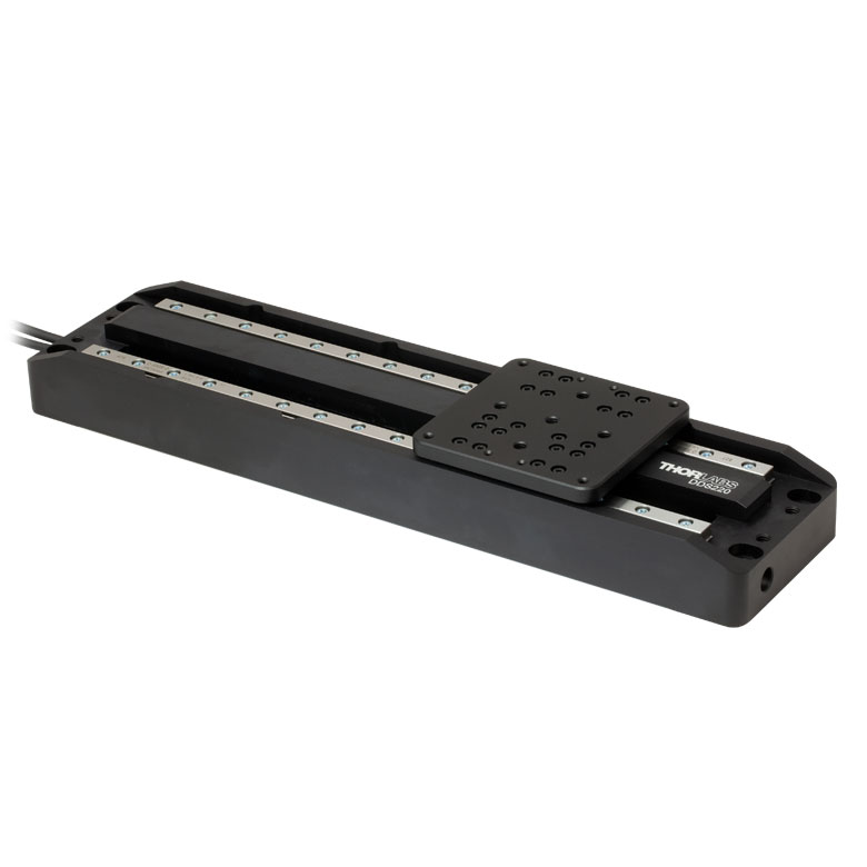
DDS Series 220 mm Stage |
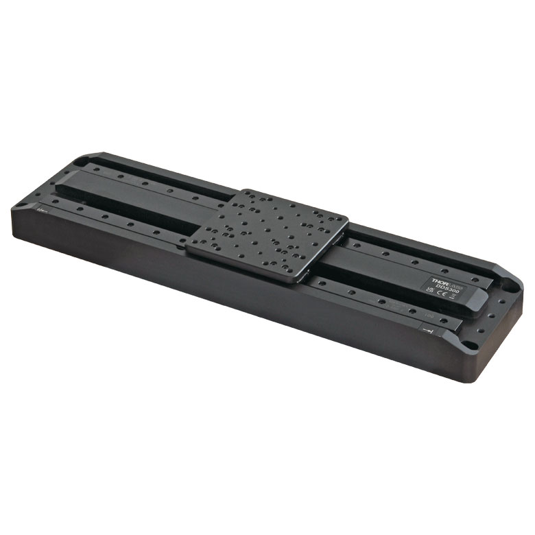
DDS Series 300 mm Stage |
DDS Series 600 mm Stage |
| Click Photo to Enlarge |
 |
 |
 |
 |
 |
| Travel | 50 mm | 100 mm | 220 mm | 300 mm | 600 mm |
| Maximum Velocity | 500 mm/s | 300 mm/s | 400 mm/s | 400 mm/s | |
| Possible Axis Configurations | X, XY | X, XY | X | X | |
| Mounting Surface Size | 60 mm x 52 mm | 88 mm x 88 mm | 120 mm x 120 mm | ||
| Additional Details | |||||

 Zoom
ZoomCharacterized by high-speed translation and high positional accuracy, the DDS050(/M) stage is well-suited for surface mapping and characterization applications where there is a need to move a camera or probe at constant velocity while simultaneously capturing data. Very precise, fine positioning and control is easily achieved through a combination of the stable closed-loop control system and a KBD101 controller.
Please Note: Magnetic components should not be mounted to the stage platform. Magnets prevent proper homing and can affect the accuracy of the stage's encoder even after the magnetic component has been removed. These stages are not suitable for operation in a vertical (Z-axis) orientation. When no power is applied, the platform of the stage has very little inertia and is virtually free running. This may make the stage unsuitable for applications where the stage's platform needs to remain in a set position when power is off.

 Zoom
Zoom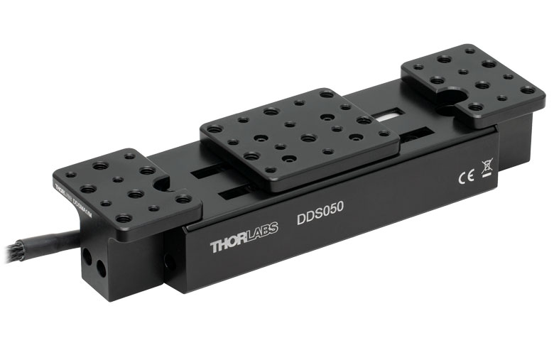
Click to Enlarge
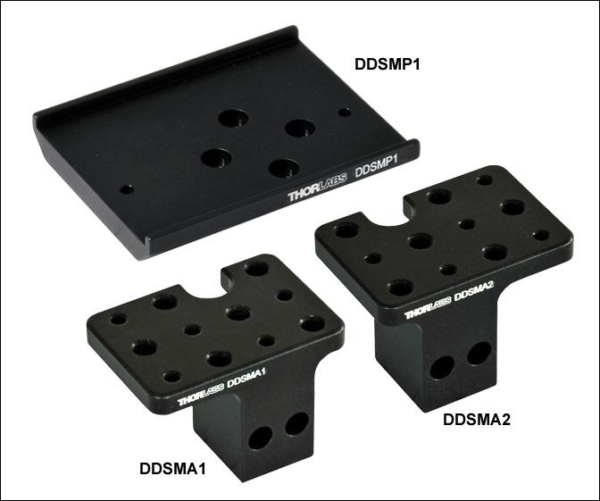
Figure 2.2 Optomechanical components can be mounted next to the travel range of the DDS050 Stage using DDSMA1 and DDSMA2 Adapter Plates.
Click for Enlarge
Figure G2.1 Two DDS050 stages can be connected in an XY configuration using the DDSMP1 XY Adapter Plate.
For 2-axis applications, two DDS050(/M) stages can be bolted together in an XY configuration using the DDSMP1(/M) adapter plate, as shown in Figure G2.1.
The DDSMA1(/M) and DDSMA2(/M) adapter plates attach to the end of the DDS050(/M) stage using the two supplied M3 x 20 screws (see Figure G2.2) and allow optomechanical components to be mounted close to the linear travel of the stage in applications such as a delay line. The plates are drilled and tapped with six 1/4"-20 (M6 x 1.0) and five 8-32 (M4 x 0.7) holes.

 Zoom
Zoom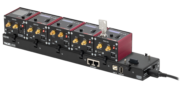
Click to Enlarge
Figure 495A KEH6 Controller Hub (Sold Separately Below) with Installed K-Cube Modules
- Front Panel Velocity Wheel and Digital Display for Controlling Motorized Stages or Actuators
- Two Bidirectional SMC Trigger Ports to Read or Control External Equipment
- Interfaces with Computer Using Included USB Cable
- Fully Compatible with Kinesis and XA Software Packages
- Compact Footprint: 60.0 mm x 60.0 mm x 49.2 mm (2.42" x 2.42" x 1.94")
- Power Supply Not Included (See Below)
Thorlabs' KBD101 K-Cube® Brushless DC Motor Controller provides local and computerized control of a single motor axis. It features a top-mounted control panel with a velocity wheel that supports four-speed bidirectional control with forward and reverse jogging as well as position presets. A backlit digital display is also included that can have the backlit dimmed or turned off using the the top-panel menu options. The front of the unit contains two bidirectional SMC trigger ports that can be used to read a 5 V external logic signal or output a 5 V logic signal to control external equipment. Each port can be independently configured.
The KBD101 controller is fully compatible with our Kinesis and XA software packages, but not all motion control devices are supported by XA at this time. A full list of supported devices can be found here. Please see the Kinesis and XA Software tab for more information.
Please note that this controller does not ship with a power supply. Compatible power supplies are listed below. Additional information can be found on the main KBD101 Brushless DC Servo Motor Controller page.

 Zoom
Zoom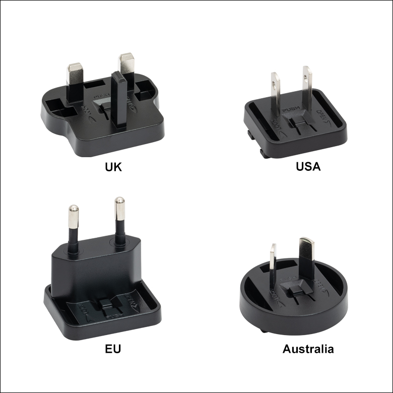
Click for Details
Figure 780B Each KPS201 power supply includes one region-specific adapter, which can be selected upon checkout.
Click to Enlarge
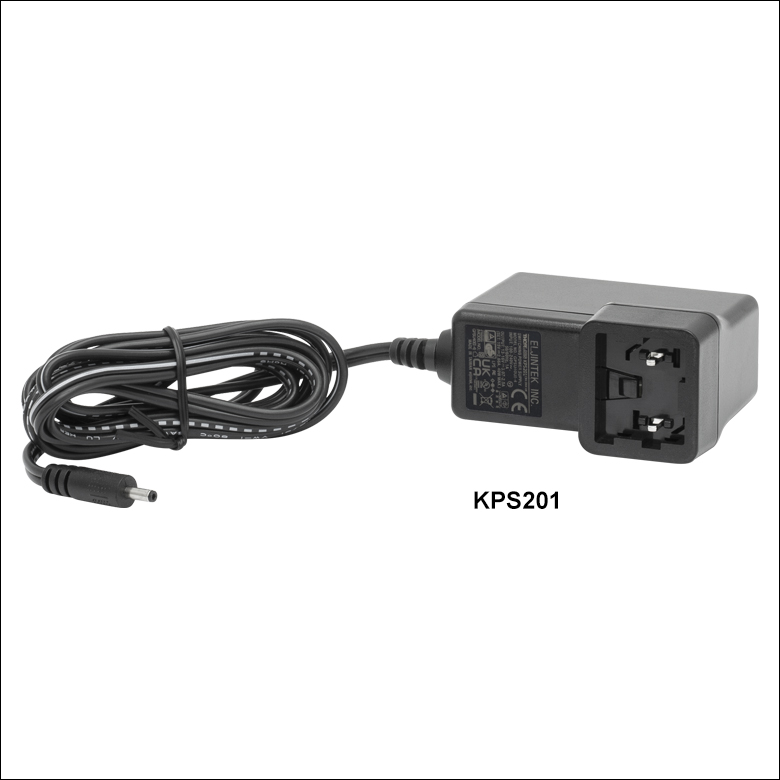
Figure 780A The KPS201 Power Supply Unit
- Individual Power Supply
- KPS201: For K-Cubes® or T-Cubes™ with 3.5 mm Jacks
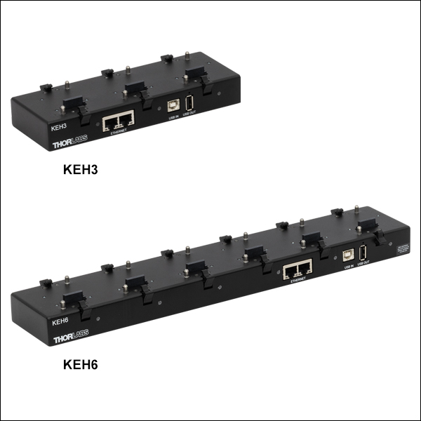
- Ethernet and USB Controller Hubs Provide Power and Communications
- KEH3: For Up to Three K-Cubes or T-Cubes
- KEH6: For Up to Six K-Cubes or T-Cubes
The KPS201 power supply outputs +15 VDC at up to 2.66 A and can power a single K-Cube or T-Cube with a 3.5 mm jack. It plugs into a standard wall outlet.
The KEH3 and KEH6 Controller Hubs contain a fully compliant USB 2.0 hub circuit and provide all communications and power distribution for up to three (Item # KEH3) or six (Item # KEH6) K-Cubes or T-Cubes (KAP101 or KAP102 adapters are needed for T-Cubes), using only a single power connection. Additionally, the hubs have two Ethernet connection ports. The second Ethernet port or USB OUT port can be connected to the input on another Controller Hub to allow multiple Controller Hub connections while still only requiring a single Ethernet or USB cable from the host PC. The hubs draw a maximum current of 4.6 A; please verify that the cubes being used do not require a total current of more than 4.6 A.
For more information on the controller hubs, see the full web presentation.