 Products Home
Brushless DC Motor Driven XY Stage
- 150 mm (5.91") of Travel Along X- and Y-Axes
- Integrated Brushless DC Servo Motors
- 10 kg (22.0 lbs) Horizontal Load Capacity
M150XY
Brushless DC Motor Driven XY Stage
150 mm X- and Y-Axis Travel
MJC2
2-Axis Microscopy Joystick
BBD302
2-Channel Brushless
DC Servo Controller


Please Wait
| M150XY(/M) Key Specificationsa | ||
|---|---|---|
| Travel Range | 150 mm (5.91") | |
| Speed | X-Axis | 170 mm/s |
| Y-Axis | 230 mm/s | |
| Acceleration (Max)b | 1000 mm/s2 | |
| Bidirectional Repeatability | ±0.25 μm | |
| Straightness / Flatness | ±2.5 μm | |
| Horizontal Load Capacityc | 10 kg (22.0 lbs) | |
| Min Incremental Movement | 100 nm | |
| Absolute On-Axis Accuracy | ±10 μm | |
| Actuator Type | Brushless DC Linear Motor | |
| Dimensions (L x W X H) | 272.4 mm x 272.4 mm x 70.1 mm (10.72" x 10.72" x 2.76") |
|

Click to Enlarge
M150XY stage with both axes at a maximum, positive travel of +75.0 mm from the neutral position.
Features
- 150 mm X- and Y- Axis Travel Ranges
- Integrated Brushless DC Servo Motors
- High-Rigidity, Precision Linear Bearings and Linear Optical Encoders
- 10 kg Horizontal Load Capacity
- 1000 mm/s2 Acceleration with ±10 µm On-Axis Accuracy
- 1/4"-20 or M6 x 1.0 mm Tapped Mounting Platforms
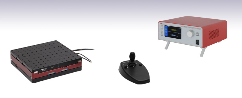
Thorlabs' M150XY(/M) brushless DC motor driven XY stage provides 150 mm of travel in both X and Y axes with maximum speeds of 170 mm/s and 230 mm/s, respectively. This stage is ideal for applications that require high speeds and high positioning accuracy, including automated alignment, surface inspection, mapping, and probing.
An innovative, low-profile design with integrated, brushless linear DC motors eliminates external housings that can impede access to the moving platform. The direct-drive technology of the brushless linear DC motors removes the need for a leadscrew, eliminating backlash. Twin, precision-grooved linear bearings provide superior rigidity and linearity with ±10 µm on-axis accuracy. The backlash-free operation coupled with high-resolution, closed-loop optical encoder feedback ensures a bidirectional repeatability of ±0.25 µm.
The top plate has one-hundred seventeen 1/4"-20 (M6 x 1.0 mm) taps on a 1" (25.0 mm) spaced grid for mounting optomechanical subassemblies. The base of each unit has machined slots with through holes that accept 1/4"-20 (M6) screws for mounting to imperial (metric) breadboards or workstations. The M150XY(/M) stage is designed with two sets of integrated control cables that allow for independent control of each axis while minimizing the possibility for the cables to become trapped as the stage moves. See the Pin Diagrams tab for more details.
Note: These stages are not suitable for operation in the vertical (Z-axis) orientation.
Recommended Controllers
While any of Thorlabs' BBD30x series brushless DC motor controllers, RBD201 Rackmount Controller, or MBD602 Controller Module with MMR60x Motion Control 19" Modular Rack System can be used with the M150XY(/M) stage, we recommend the BBD302 two-channel brushless DC motor controller as it provides the most compact footprint for controlling both axes. The BBD30x series controllers use Thorlabs' Kinesis software and allow for easy, out-of-the-box configuration. Any of the multi-channel controllers* also support synchronous control of both axes of the stage. Please note that two BBD301 single-axis controllers would be needed to achieve independent, simultaneous control of both axes. BBD30x controllers provide user-configurable, S-Curve or Trapezoidal velocity profiles that enable fast, smooth positioning without vibration or shock. See the presentation below for more details.
*When driving the M150XY(/M) stage with a BBD303 three-channel controller, avoid connecting a third axis simultaneously to achieve the best performance.
Motion Control Software
The stage is designed to be used with Thorlabs Kinesis® software and is shipped with default parameters pre-configured. Please see the Motion Control Software tab and the M150XY(/M) manual for more details.
Joystick Option
The MJC2 two-axis joystick is available for precise, remote positioning applications. See the presentation below for more details.
| M150XY(/M) Stage | ||
|---|---|---|
| Axis Travel Direction | X-Axis | Y-Axis |
| Travel Range | 150 mm (5.91") | |
| Maximum Speed | 170 mm/s | 230 mm/s |
| Maximum Accelerationa | 1000 mm/s2 | |
| Bidirectional Repeatability | ±0.25 μm | |
| Backlashb | N/A (No Lead Screw) | |
| Encoder Resolution | 50 nm | |
| Minimum Incremental Motion | 100 nm | |
| Horizontal Load Capacityc | 10 kg (22.2 lbs) | |
| Absolute On-Axis Accuracy | ±10 μm | |
| Straightness / Flatness | ±2.5 μm | |
| Pitch | ±80 μm | ±40 μm |
| Yaw | ±65 μm | ±65 μm |
| Continuous Motor Force | 10.0 N | 10.0 N |
| Peak Motor Force (2 Second) | 20.0 N | 20.0 N |
| Cable Length | 2970 mm (116.92") | 2700 mm (106.29") |
| General | ||
| Bearing Type | High-Rigidity Recirculating Precision Linear Bearing | |
| Limit Switches | Magnetic Sensor at Each End of Stage | |
| Operating Temperature Ranged | 5 to 40 °C (41 to 104 °F) | |
| Motor Type | Brushless DC Linear Motor | |
| Dimensions (Mid Travel) L x W x H | 10.72" x 10.72" x 2.76" (272.4 mm x 272.4 mm x 70.1 mm) |
|
| Weight (Excluding Cables) | 8.9 kg (19.6 lbs) | |

Click for Detail
M150XY/M Mechanical Features

Click for Detail
M150XY Mechanical Features
M150XY(/M) Incremental Motion

Click to Enlarge
The plot above shows the minimum incremental motion of the M150XY(/M) stage's X-axis. The minimum incremental motion is 50 nm. The position shown is taken as an average position over the 2 second dwell time after each movement.

Click to Enlarge
The plot above shows the minimum incremental motion of the M150XY(/M) stage's Y-axis. The minimum incremental motion is 50 nm. The position shown is taken as an average position over the 2 second dwell time after each movement.

Click to Enlarge
The plot above shows the incremental motion of the M150XY(/M) stage's X-axis with 100 nm steps. The position shown is taken as an average position over the 2 second dwell time after each movement.
 Click to Enlarge
The plot above shows the incremental motion of the M150XY(/M) stage's Y-axis with 100 nm steps. The position shown is taken as a n average position over the 2 second dwell time after each movement.
Click to Enlarge
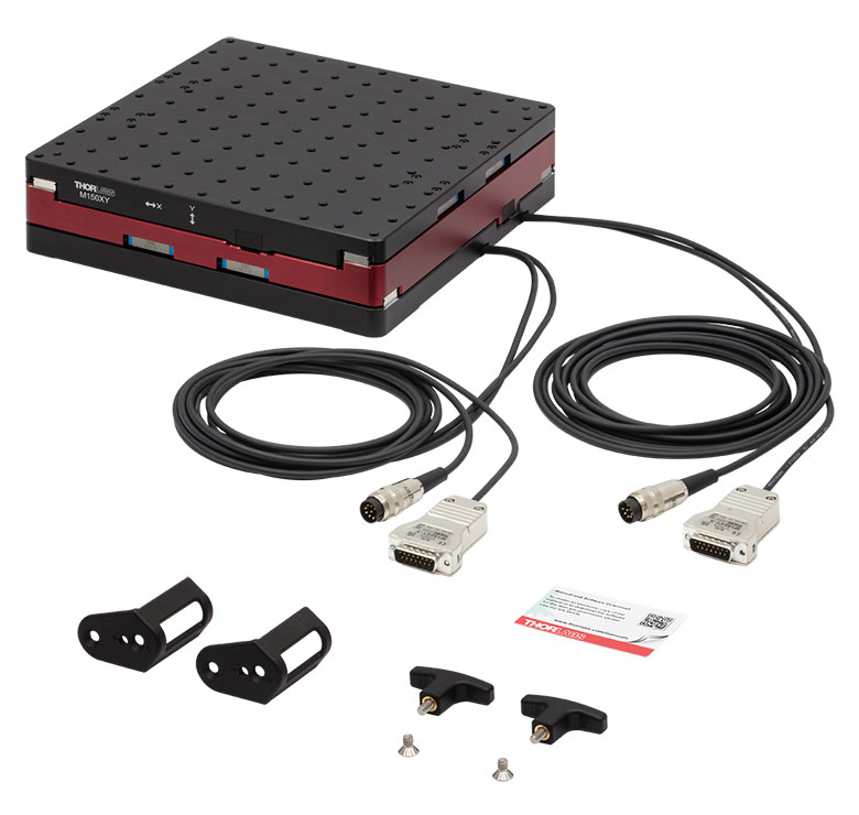
M150XY(/M) Stage and Included Accessories
The following accessories are included in Item # M150XY(/M):
- Brushless DC Motor Driven XY Stage
- Two T-Shaped Transport Handles
- Two Transport Brackets
- Two 1/4"-20 (M6 x 1.0 mm) Countersunk Hex Socket Screws (For Mounting the Transport Brackets to the Stage)
- Manual and Software Download Card
- Unpacking Guide
The M150XY(/M) stage should only be moved with the T-shaped handles and transportation brackets included in the package. The mounting locations for the transportation brackets are different for the M150XY imperial stage and the M150XY/M metric stage as shown below. Do not overtighten the screws for the T-shaped handles or transportation brackets.
The M150XY(/M) stage should be moved with the transportation brackets and T-shaped handles, and held such that the stage remains in the horizontal (XY-axis) orientation. The stage is not designed to be transported or mounted in a vertical (Z-axis) orientation.
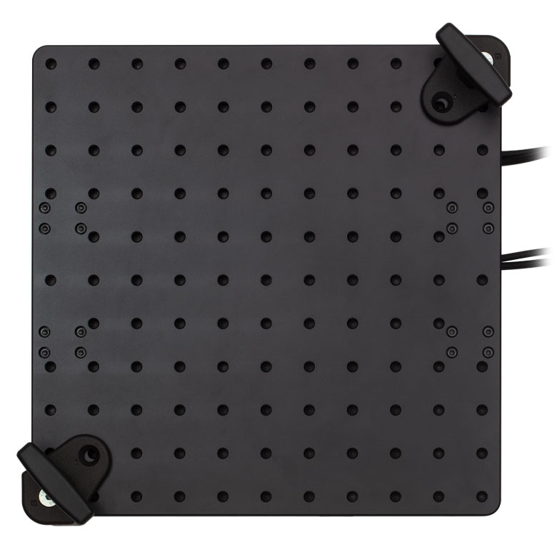
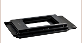
Click to Enlarge
Top view of the M150XY/M stage with the transportation brackets and T-shaped handles installed.

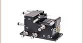
Click to Enlarge
Exploded view of the M150XY stage and one of the transportation brackets and T-shaped handles. The red dashed line shows the hole where the T-shaped handle should be inserted through the transportation bracket and secured to the top of the stage. This hole is in the same location and uses the same M6 x 1.0 mm thread for both imperial and metric versions of the stage.

Click to Enlarge
Top view of the M150XY stage with the included transportation bracket. The 1/4"-20 countersunk hex socket screw can be seen securing the transportation bracket in place using the corresponding 1/4"-20 tapped hole on the top of the stage.

Click to Enlarge
Top view of the M150XY/M stage with the included transportation bracket. The M6 x 1.0 mm countersunk hex socket screw can be seen securing the transportation bracket in place using the corresponding M6 x 1.0 mm tapped hole on the top of the stage.
Each axis has a 15-Pin D-type connector and an 8-Pin DIN type connector that are designed to connect to a BBD30x series controller. Note that the X-axis and Y-axis cable lengths are 116.93" (2970.0 mm) and 106.30" (2700.0 mm), respectively. This is due to the internal ducting used within the stage to minimize the chance the wires get trapped while the stage is in motion.
15-Pin Male D-Type
Encoder Feedback Connector
| Pin | Description | Pin | Description |
|---|---|---|---|
| 1 | Not Connected | 9 | Ground |
| 2 | Ground | 10 | Limit Switch + |
| 3 | Not Connected | 11 | Limit Switch - |
| 4 | Enc Index - | 12 | Enc Index + |
| 5 | QB - | 13 | QB + |
| 6 | QA - | 14 | QA + |
| 7a | 5 V | 15 | Not Connected |
| 8a | 5 V |
8-Pin Male DIN Type
Motor Drive Connector
| Pin | Description | Pin | Description |
|---|---|---|---|
| 1 | Motor Phase V | 5 | Stage ID |
| 2 | Ground | 6 | Ground |
| 3 | Thermistor (Not Used) | 7 | Motor Phase W |
| 4 | Motor Phase U | 8 | Enable |
Note: The M150XY(/M) brushless DC motor driven XY stage is designed to be operated using a BBD30x series controller, which can be controlled by a PC running Thorlabs' Kinesis software. Alternatively, Thorlabs' legacy APT software package may be used if desired.
Thorlabs offers two platforms to drive our wide range of motion controllers: our Kinesis® software package or the legacy APT™ (Advanced Positioning Technology) software package. Either package can be used to control devices in the Kinesis family, which covers a wide range of motion controllers ranging from small, low-powered, single-channel drivers (such as the K-Cubes™ and T-Cubes™) to high-power, multi-channel, modular 19" rack nanopositioning systems (the APT Rack System).
The Kinesis Software features .NET controls which can be used by 3rd party developers working in the latest C#, Visual Basic, LabVIEW™, or any .NET compatible languages to create custom applications. Low-level DLL libraries are included for applications not expected to use the .NET framework. A Central Sequence Manager supports integration and synchronization of all Thorlabs motion control hardware.
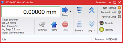
Kinesis GUI Screen
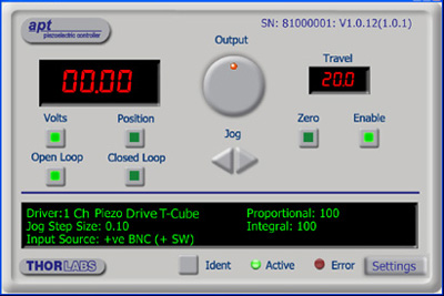
APT GUI Screen
Our legacy APT System Software platform offers ActiveX-based controls which can be used by 3rd party developers working on C#, Visual Basic, LabVIEW™, or any Active-X compatible languages to create custom applications and includes a simulator mode to assist in developing custom applications without requiring hardware.
By providing these common software platforms, Thorlabs has ensured that users can easily mix and match any of the Kinesis and APT controllers in a single application, while only having to learn a single set of software tools. In this way, it is perfectly feasible to combine any of the controllers from single-axis to multi-axis systems and control all from a single, PC-based unified software interface.
The software packages allow two methods of usage: graphical user interface (GUI) utilities for direct interaction with and control of the controllers 'out of the box', and a set of programming interfaces that allow custom-integrated positioning and alignment solutions to be easily programmed in the development language of choice.
A range of video tutorials is available to help explain our APT system software. These tutorials provide an overview of the software and the APT Config utility. Additionally, a tutorial video is available to explain how to select simulator mode within the software, which allows the user to experiment with the software without a controller connected. Please select the APT Tutorials tab above to view these videos.
Software
Kinesis Version 1.14.47
The Kinesis Software Package, which includes a GUI for control of Thorlabs' Kinesis and APT™ system controllers.
Also Available:
- Communications Protocol
Software
APT Version 3.21.6
The APT Software Package, which includes a GUI for control of Thorlabs' APT™ and Kinesis system controllers.
Also Available:
- Communications Protocol
Thorlabs' Kinesis® software features new .NET controls which can be used by third-party developers working in the latest C#, Visual Basic, LabVIEW™, or any .NET compatible languages to create custom applications.
C#
This programming language is designed to allow multiple programming paradigms, or languages, to be used, thus allowing for complex problems to be solved in an easy or efficient manner. It encompasses typing, imperative, declarative, functional, generic, object-oriented, and component-oriented programming. By providing functionality with this common software platform, Thorlabs has ensured that users can easily mix and match any of the Kinesis controllers in a single application, while only having to learn a single set of software tools. In this way, it is perfectly feasible to combine any of the controllers from the low-powered, single-axis to the high-powered, multi-axis systems and control all from a single, PC-based unified software interface.
The Kinesis System Software allows two methods of usage: graphical user interface (GUI) utilities for direct interaction and control of the controllers 'out of the box', and a set of programming interfaces that allow custom-integrated positioning and alignment solutions to be easily programmed in the development language of choice.
For a collection of example projects that can be compiled and run to demonstrate the different ways in which developers can build on the Kinesis motion control libraries, click on the links below. Please note that a separate integrated development environment (IDE) (e.g., Microsoft Visual Studio) will be required to execute the Quick Start examples. The C# example projects can be executed using the included .NET controls in the Kinesis software package (see the Kinesis Software tab for details).
 |
Click Here for the Kinesis with C# Quick Start Guide Click Here for C# Example Projects Click Here for Quick Start Device Control Examples |
|
LabVIEW
LabVIEW can be used to communicate with any Kinesis- or APT-based controller via .NET controls. In LabVIEW, you build a user interface, known as a front panel, with a set of tools and objects and then add code using graphical representations of functions to control the front panel objects. The LabVIEW tutorial, provided below, provides some information on using the .NET controls to create control GUIs for Kinesis- and APT-driven devices within LabVIEW. It includes an overview with basic information about using controllers in LabVIEW and explains the setup procedure that needs to be completed before using a LabVIEW GUI to operate a device.
 |
Click Here to View the LabVIEW Guide Click Here to View the Kinesis with LabVIEW Overview Page |
|
| Posted Comments: | |
user
(posted 2023-10-06 16:41:09.463) We like to use it to mount a cryostat, but there are metal hose connections to it. May I know what is the maximum drag force (from the hoses to our cryostat) can the stage withstands? do'neill
(posted 2023-10-30 06:27:42.0) Response from Daniel at Thorlabs. I will reach out to you directly to discuss your application as this will depend on exactly what you are trying to do, for example, which axis you will be looking at, the speed you are driving it, etc. user
(posted 2023-09-11 08:21:27.41) 2" or 3" versions, ideally vacuum compatible, would be very useful in confined spaces. Keeping total system cost under $10k would make it easier for some groups to purchase (stage + controller + joystick). |
Motorized Linear Translation Stages
Thorlabs' motorized linear translation stages are offered in a range of maximum travel distances, from a stage with 20 µm of piezo translation to our 600 mm direct drive stage. Many of these stages can be assembled in multi-axis configurations, providing XY or XYZ translation. For fiber coupling applications, please see our multi-axis stages, which offer finer adjustment than our standard motorized translation stages. In addition to motorized linear translation stages, we offer motorized rotation stages and goniometers. We also offer manual translation stages.
Piezo Stages
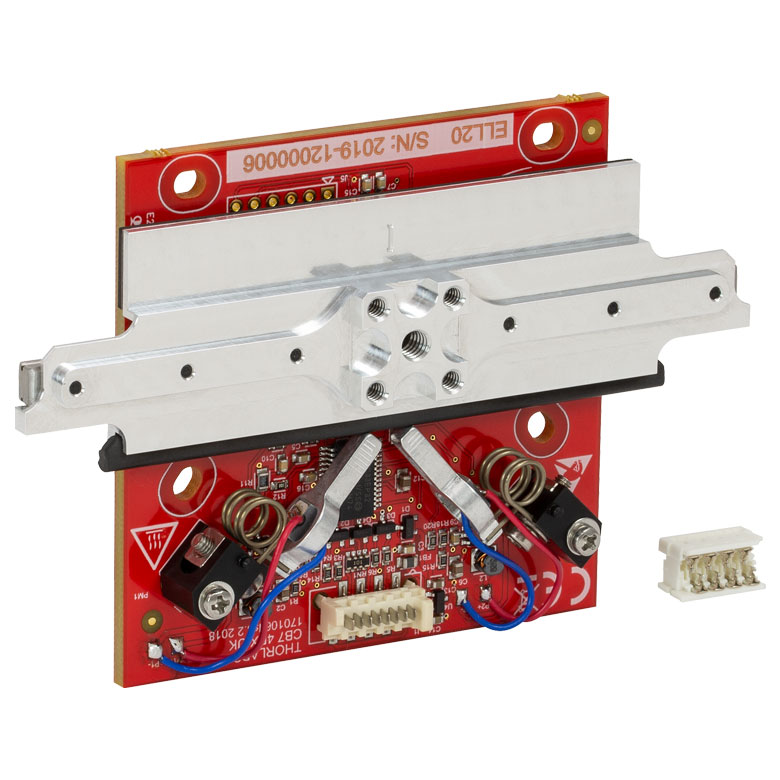
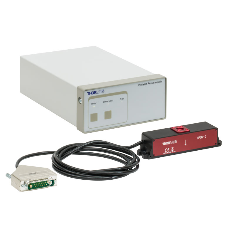
These stages incorporate piezoelectric elements in a variety of drive mechanisms. ORIC® stages incorporate piezo inertia drives that use "stick-slip" friction properties to obtain extended travel ranges. Our Nanoflex™ translation stages use standard piezo chips along with manual actuators. Elliptec® stages use resonant piezo motors to push and pull the moving platform through resonant elliptical motion. Our LPS710E z-axis stage features a mechanically amplified piezo design and includes a matched controller.
| Piezoelectric Stages | ||||
|---|---|---|---|---|
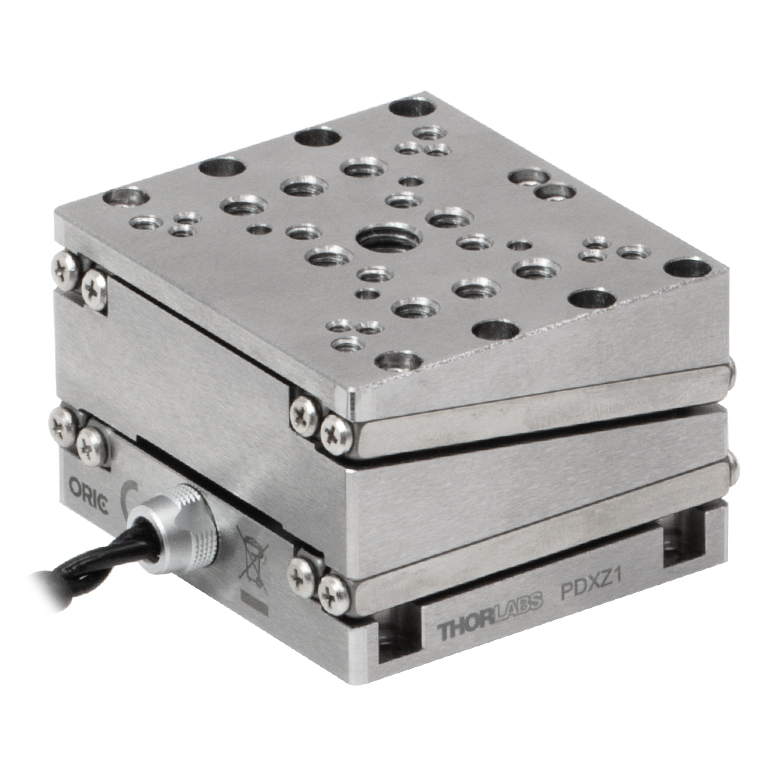
| Product Family | ORIC® PDXZ1 Closed-Loop 4.5 mm Vertical Stage |
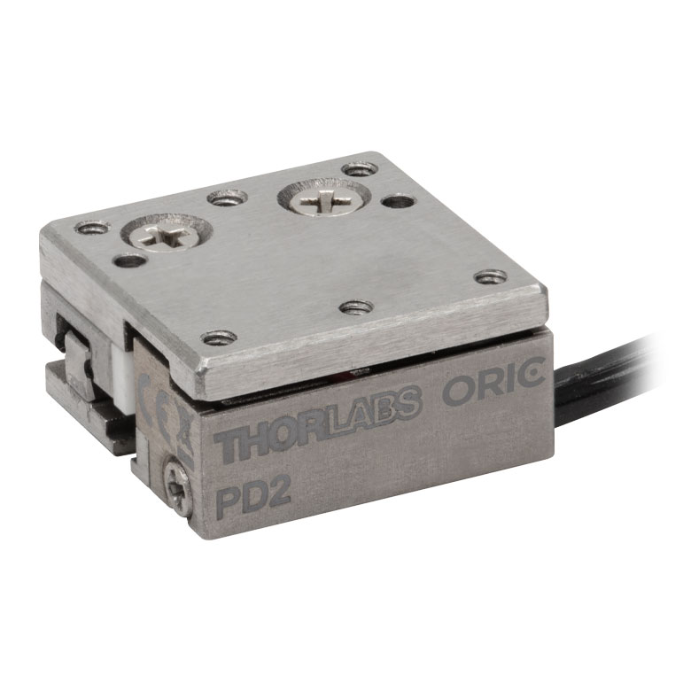
ORIC® PD2 Open-Loop 5 mm Stage |
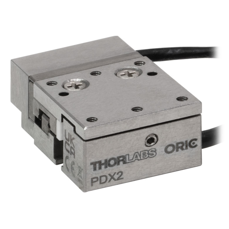
ORIC® PDX2 Closed-Loop 5 mm Stage |
|
| Click Photo to Enlarge |
 |
 |
 |
|
| Travel | 4.5 mm | 5 mm | ||
| Speed | 1 mm/s (Typ.)a | 10 mm/s (Typ. Max)b | 8 mm/s (Typ.)c | |
| Drive Type | Piezoelectric Inertia Drive | |||
| Possible Axis Configurations | Z | X, XY, XYZ | ||
| Mounting Surface Size |
45.0 mm x 42.0 mm | 13 mm x 13 mm | ||
| Additional Details | ||||
| Piezoelectric Stages | |||||
|---|---|---|---|---|---|
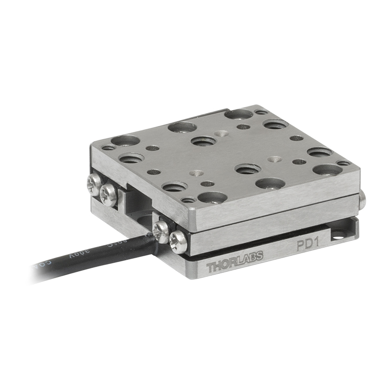
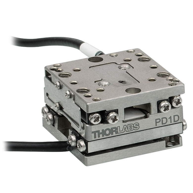
| Product Family | ORIC® PD1 Open-Loop 20 mm Stage |
ORIC® PD1D Open-Loop 20 mm Monolithic XY Stage |
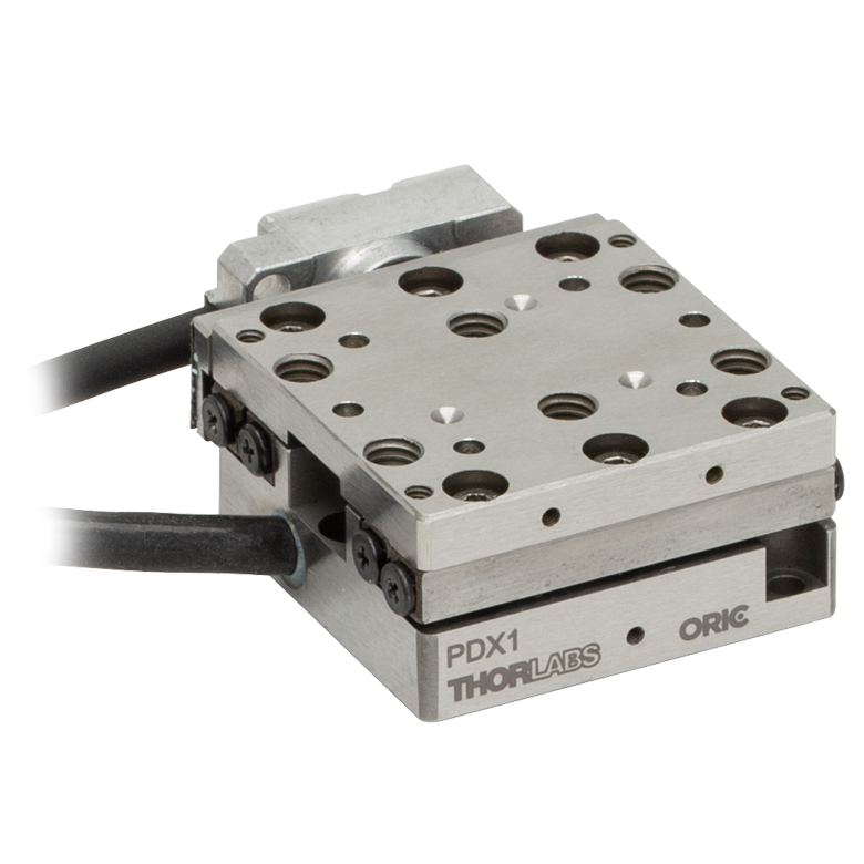
ORIC® PDX1 Closed-Loop 20 mm Stage |
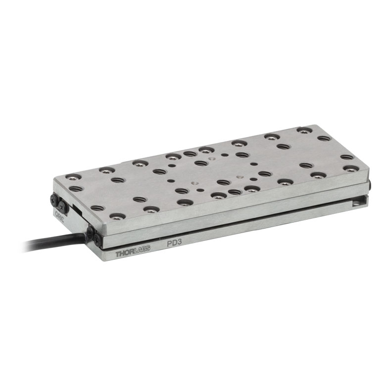
ORIC® PD3 Open-Loop 50 mm Stage |
|
| Click Photo to Enlarge |
 |
 |
 |
 |
|
| Travel | 20 mm | 50 mm | |||
| Speed | 3 mm/s (Typ. Max)a | 20 mm/s (Typ. Max)b | 10 mm/sc | ||
| Drive Type | Piezoelectric Inertia Drive | ||||
| Possible Axis Configurations | X, XY, XYZ | XY, XYZ | X, XY, XYZ | X, XY, XYZ | |
| Mounting Surface Size |
30 mm x 30 mm | 80 mm x 30 mm | |||
| Additional Details | |||||
| Piezoelectric Stages | ||||||
|---|---|---|---|---|---|---|
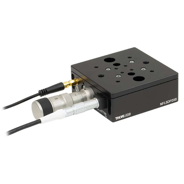
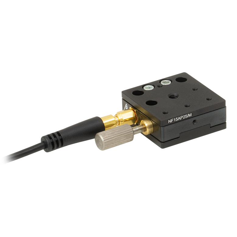
| Product Family | Nanoflex™ 20 µm Stage with 5 mm Actuator |
Nanoflex™ 25 µm Stage with 1.5 mm Actuator |
Elliptec® 28 mm Stage | Elliptec® 60 mm Stage | LPS710E 1.1 mm Vertical Stage | |
| Click Photo to Enlarge |
 |
 |
 |
 |
 |
|
| Travel | 20 µm + 5 mm Manual | 25 µm + 1.5 mm Manual | 28 mm | 60.0 mm | 1.1 mm | |
| Maximum Velocity | - | 180 mm/s | 90 mm/s | - | ||
| Drive Type | Piezo with Manual Actuator | Resonant Piezoelectric Motor | Amplified Piezo | |||
| Possible Axis Configurations | X, XY, XYZ | X | Z | |||
| Mounting Surface Size | 75 mm x 75 mm | 30 mm x 30 mm | 15 mm x 15 mm | 21 mm x 21 mm | ||
| Additional Details | ||||||
Stepper Motor Stages
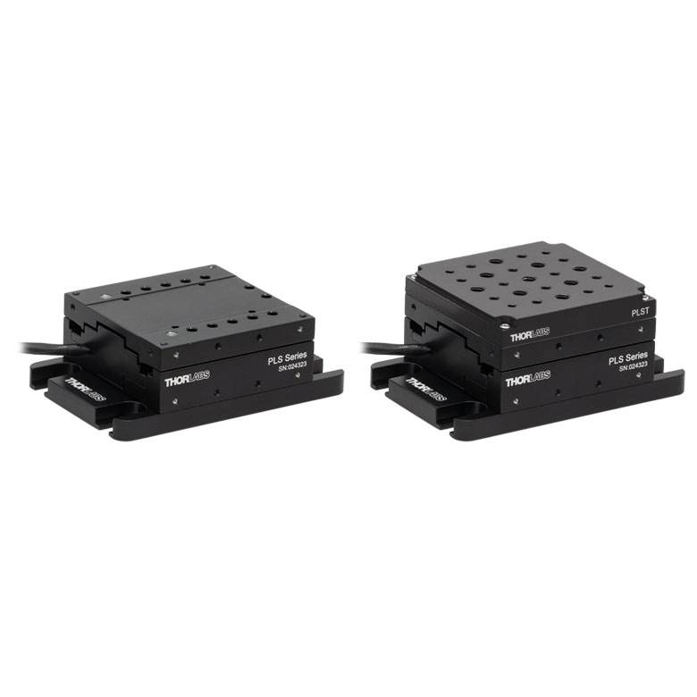
These translation stages feature removable or integrated stepper motors and long travel ranges up to 300 mm. Many of these stages either have integrated multi-axis capability (PLSXY) or can be assembled into multi-axis configurations (PLSX, LNR Series, NRT Series, and LTS Series stages). The MLJ150 stage also offers high load capacity vertical translation.
| Stepper Motor Stages | |||||
|---|---|---|---|---|---|
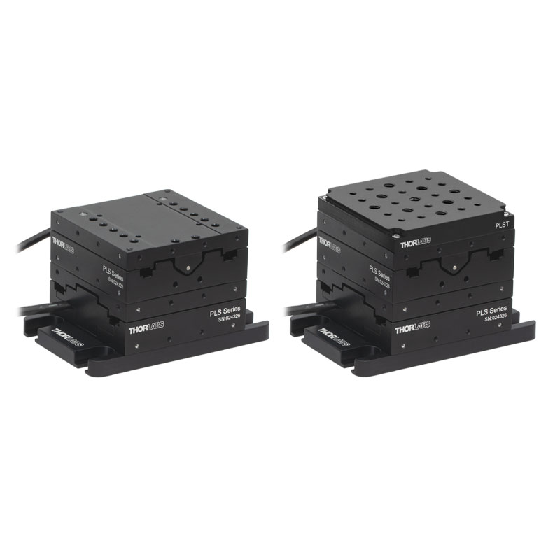
| Product Family | PLSX with and without PLST(/M) Top Plate 1" Stage |
PLSXY with and without PLST(/M) Top Plate 1" Stage |
LNR Series 25 mm Stage |
LNR Series 50 mm Stage |
|
| Click Photo to Enlarge |
 |
 |
 |
 |
|
| Travel | 1" | 25 mm | 50 mm | ||
| Maximum Velocity | 7.0 mm/s | 2.0 mm/s | 50 mm/s | ||
| Possible Axis Configurations |
X, XY | X, XY, XYZ | X, XY, XYZ | ||
| Mounting Surface Size |
3" x 3" | 60 mm x 60 mm | 100 mm x 100 mm | ||
| Additional Details | |||||
| Stepper Motor Stages | ||||||
|---|---|---|---|---|---|---|
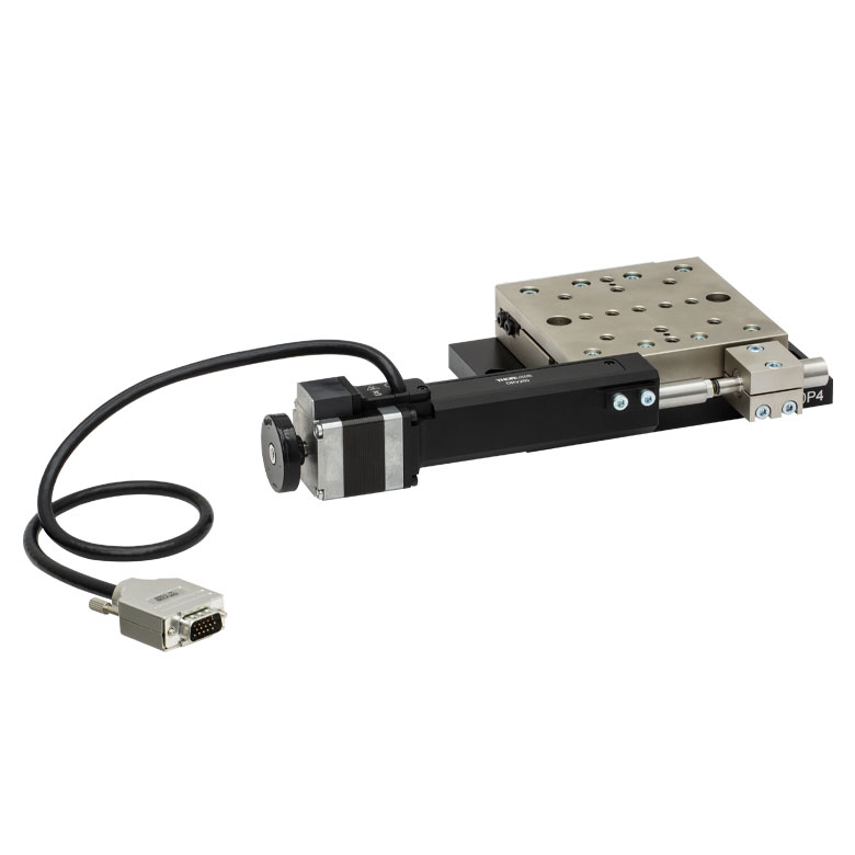
| Product Family | NRT Series 100 mm Stage |
NRT Series 150 mm Stage |
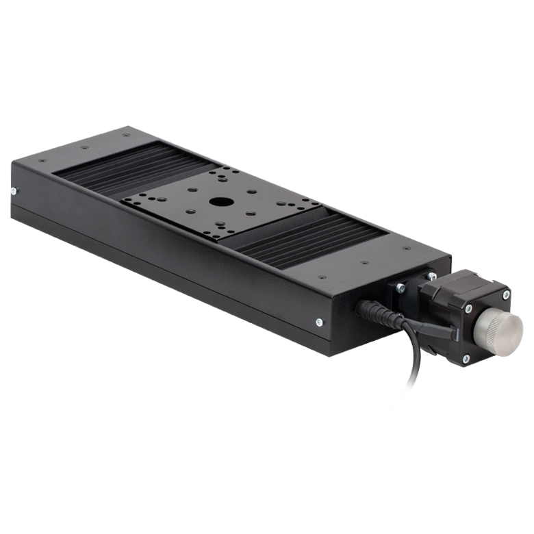
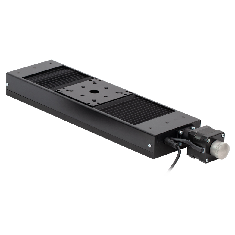
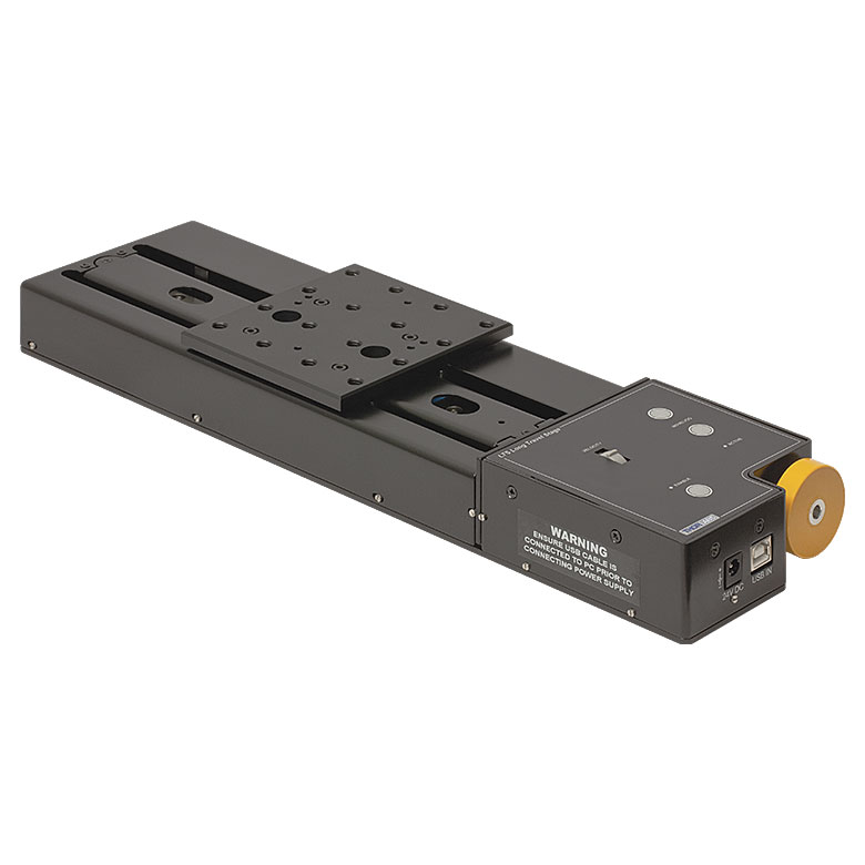
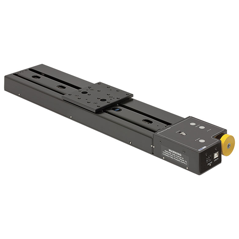
LTS Series 150 mm Stage |
LTS Series 300 mm Stage |
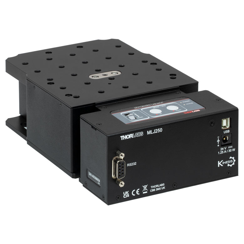
MLJ250 50 mm Vertical Stage |
|
| Click Photo to Enlarge |
 |
 |
 |
 |
 |
|
| Travel | 100 mm | 150 mm | 150 mm | 300 mm | 50 mm | |
| Maximum Velocity | 30 mm/s | 50 mm/s | 3.0 mm/s | |||
| Possible Axis Configurations |
X, XY, XYZ | X, XY, XYZ | Z | |||
| Mounting Surface Size |
84 mm x 84 mm | 100 mm x 90 mm | 148 mm x 131 mm | |||
| Additional Details | ||||||
DC Servo Motor Stages
Thorlabs offers linear translation stages with removable or integrated DC servo motors. These stages feature low profiles and many can be assembled in multi-axis configurations.
| DC Servo Motor Stages | ||||
|---|---|---|---|---|
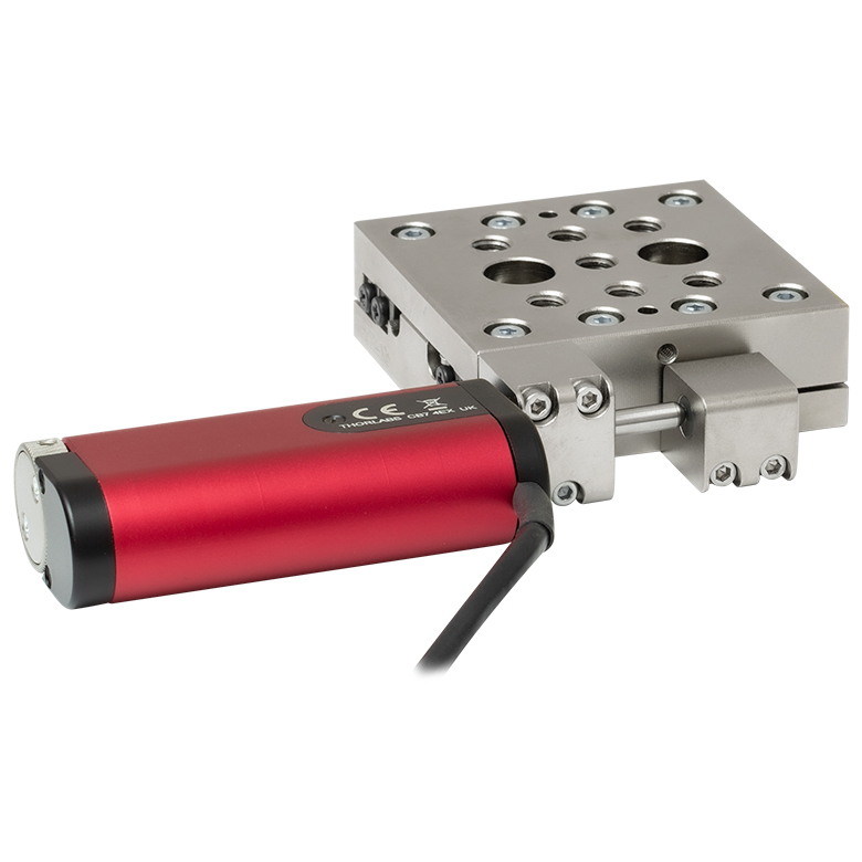
| Product Family | MT Series 12 mm Stages |
PT Series 25 mm Stages |
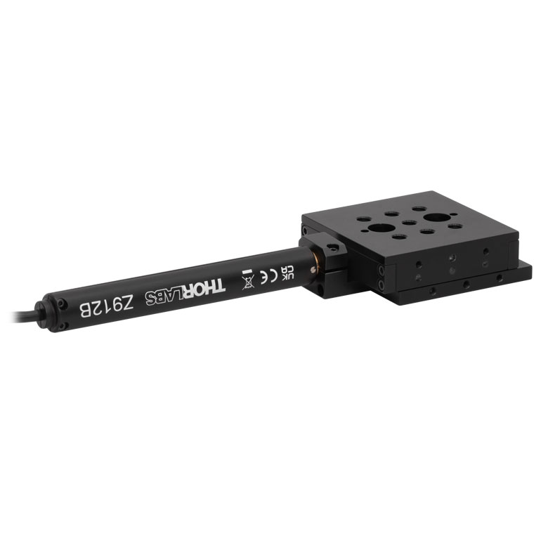
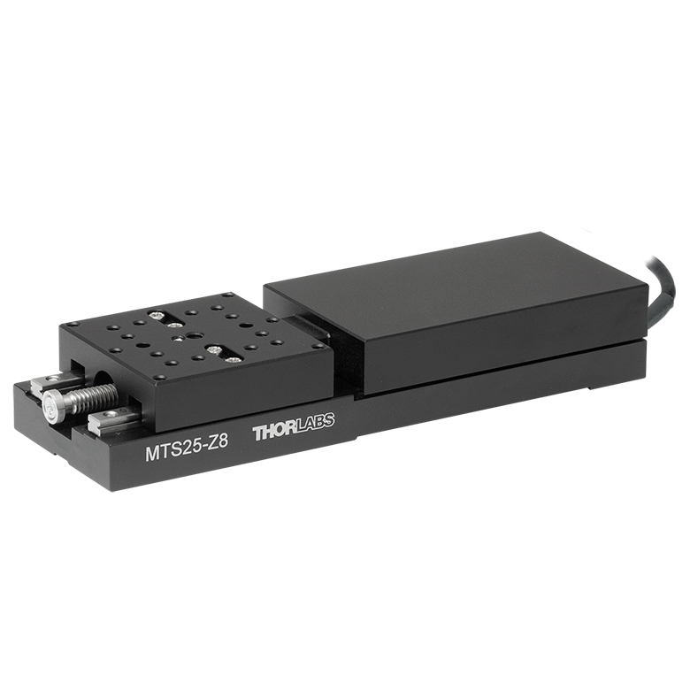
MTS Series 25 mm Stage |
MTS Series 50 mm Stage |
| Click Photo to Enlarge |
 |
 |
 |
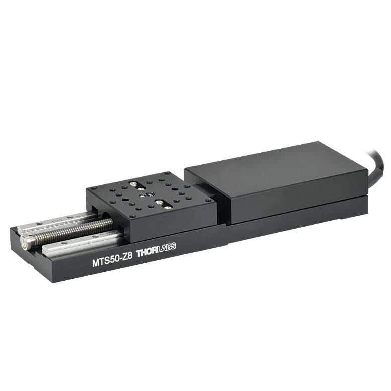 |
| Travel | 12 mm | 25 mm | 25 mm | 50 mm |
| Maximum Velocity | 2.6 mm/s | 2.4 mm/s | ||
| Possible Axis Configurations | X, XY, XYZ | X, XY, XYZ | ||
| Mounting Surface Size |
61 mm x 61 mm | 101.6 mm x 76.2 mm | 43 mm x 43 mm | |
| Additional Details | ||||
| DC Servo Motor Stages | ||||
|---|---|---|---|---|
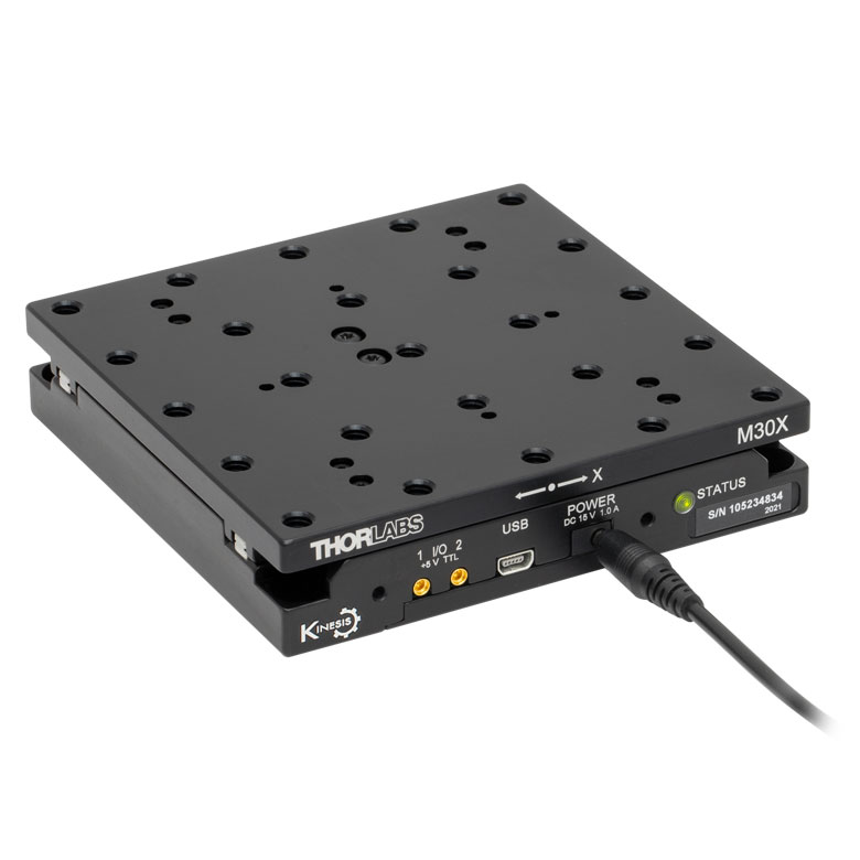
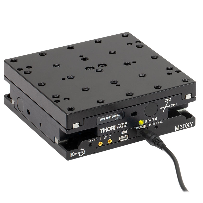
| Product Family | M30 Series 30 mm Stage |
M30 Series 30 mm Monolithic XY Stage |
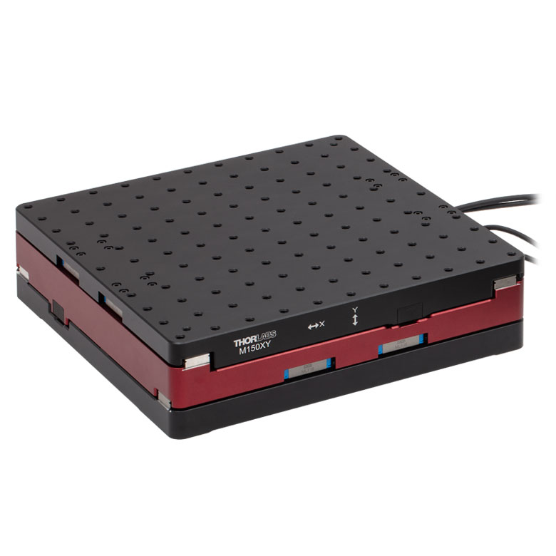
M150 Series 150 mm XY Stage |
KVS30 30 mm Vertical Stage |
| Click Photo to Enlarge |
 |
 |
 |
 |
| Travel | 30 mm | 150 mm | 30 mm | |
| Maximum Velocity | 2.4 mm/s | X-Axis: 170 mm/s Y-Axis: 230 mm/s |
8.0 mm/s | |
| Possible Axis Configurations | X, Z | XY, XZ | XY | Z |
| Mounting Surface Size |
115 mm x 115 mm | 272.4 mm x 272.4 mm | 116.2 mm x 116.2 mm | |
| Additional Details | ||||
Direct Drive Stages
These low-profile stages feature integrated brushless DC servo motors for high speed translation with zero backlash. When no power is applied, the platforms of these stages have very little inertia and are virtually free running. Hence these stages may not be suitable for applications where the stage's platform needs to remain in a set position when the power is off. We do not recommend mounting these stages vertically.
| Direct Drive Stages | |||||
|---|---|---|---|---|---|
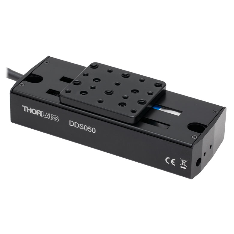
| Product Family | DDS Series 50 mm Stage |
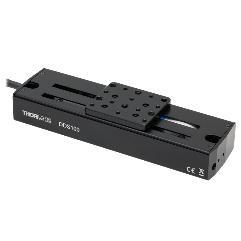
DDS Series 100 mm Stage |
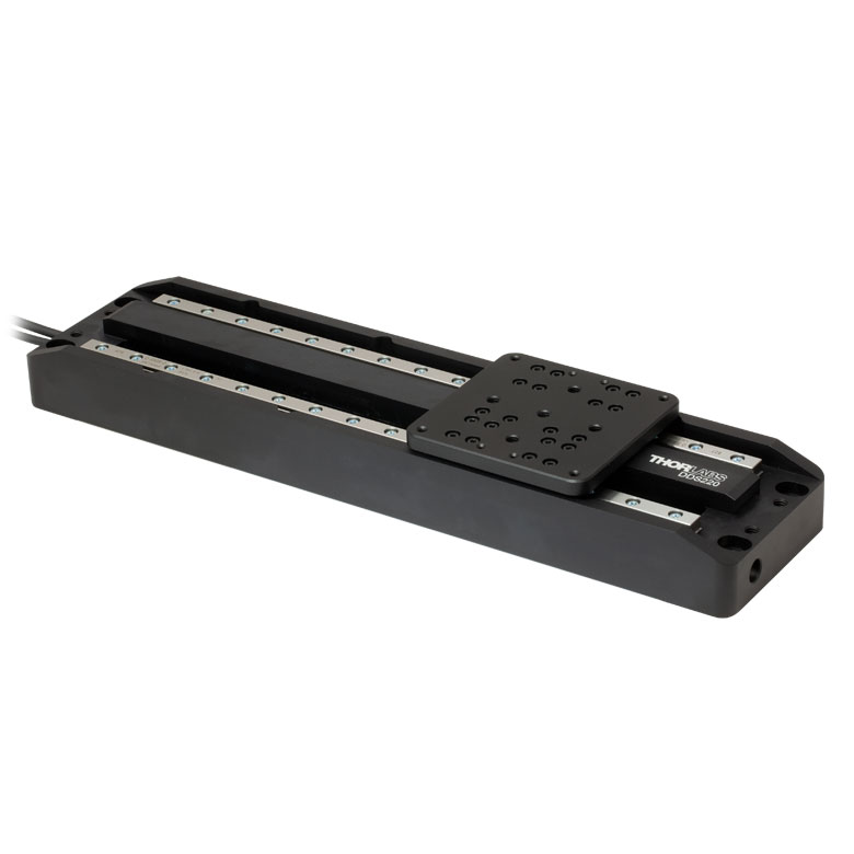
DDS Series 220 mm Stage |
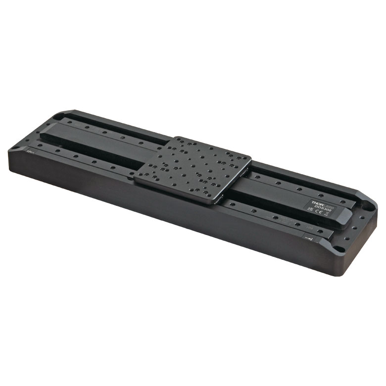
DDS Series 300 mm Stage |
DDS Series 600 mm Stage |
| Click Photo to Enlarge |
 |
 |
 |
 |
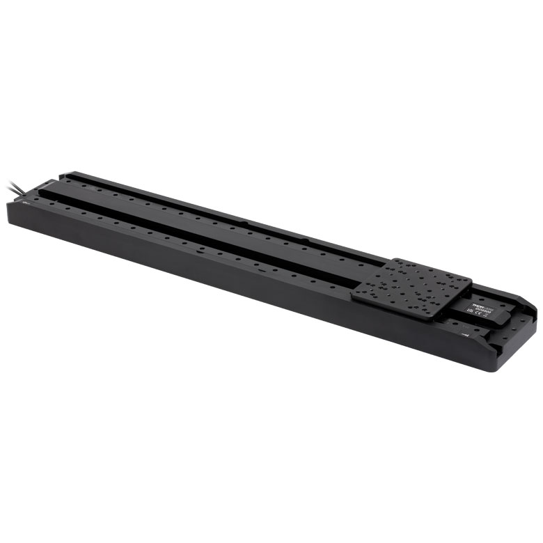 |
| Travel | 50 mm | 100 mm | 220 mm | 300 mm | 600 mm |
| Maximum Velocity | 500 mm/s | 300 mm/s | 400 mm/s | 400 mm/s | |
| Possible Axis Configurations | X, XY | X, XY | X | X | |
| Mounting Surface Size | 60 mm x 52 mm | 88 mm x 88 mm | 120 mm x 120 mm | ||
| Additional Details | |||||

 Zoom
Zoom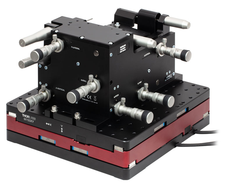
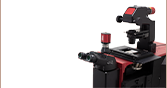
Click to Enlarge
A MAX601D 6-Axis NanoMax Stage for precise fiber alignment mounted on an M150XY stage.
- 150 mm Travel in Both X- and Y-Axis
- Travel Speeds Up To:
- X-Axis: 170 mm/s
- Y-Axis: 230 mm/s
- 100 nm Minimum Incremental Motion
- ±0.25 µm Bidirectional Repeatability
- Control with the Kinesis Software Package
Thorlabs' M150XY(/M) brushless DC motor driven XY stage provides up to 150 mm of precise, stable travel in both X- and Y-axes with high repeatability. The large 10.72" x 10.72" (272.4 mm x 272.4 mm) stage provides 117 holes with 1/4"-20 (M6 x 1.0 mm) taps spaced by 1" (25.0 mm) in a 10" x 10" (250 mm x 250 mm) grid. The M150XY(/M) stage is capable of moving loads up to 10 kg (22.0 lbs) at speeds up to 170 mm/s and 230 mm/s for the X-axis and Y-axis, respectively. Note that the M150XY(/M) stage cannot be disassembled into two single-axis stages.
Two sets of cables, each with 15-pin D-type and 8-pin DIN connectors designed to connect to the BBD30x series controllers, allow for independent control of each axis of the M150XY(/M) stage. When the stage is connected to a BBD30x series controller, the default settings stored within the EEPROM of the 8-pin DIN type connector will be loaded into the controller upon start up. While any of the BBD30x series brushless DC motor controllers can be used with the M150XY(/M) stage, we recommend the BBD302 two-channel controller as it provides control of both axes in the most compact footprint.

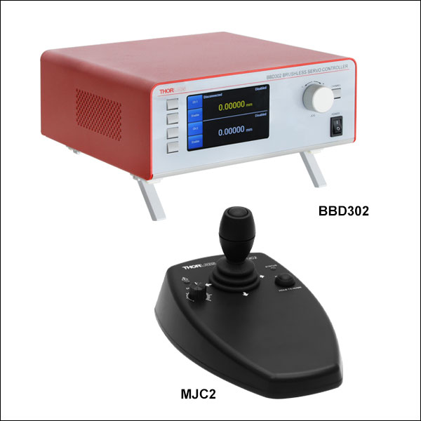 Zoom
Zoom- BBD302: Recommended Two-Channel Controller for the M150XY(/M) Stage
- MJC2: Optional Two-Axis Remote Control Joystick
We recommend using the BBD302 Two-Channel Brushless DC Servo Controller to drive the M150XY(/M) stage. This controller offers simultaneous, two-axis control with a user-configurable S-curve acceleration/deceleration profile for fast, smooth positioning without vibration or shock. The BBD302 controller is also ideal for operation at high speeds (hundreds of mm/s) and high encoder resolution. Thorlabs' Kinesis® and APT™ software interfaces can be used to operate the controller, enabling easy integration into automated motion control applications. For greater flexibility, communication with a PC is supported through the controller's USB or RS232 interface.
The controller is supplied with a software development kit (SDK), useful to system integrators and other automation specialists who need to combine operation of the stage with other automated accessories. The fully documented SDK supports all major development languages running on Windows, such as LabVIEW, C++, and MATLAB, and comes in the form of ActiveX libraries or a conventional dynamic link library (DLL). The full web presentation for the BBD30x brushless DC motor controllers is available here.
The MJC2 joystick is also available for applications requiring precise, remote controlled, manual positioning of both X- and Y-axes of the M150XY(/M) stage. For most applications, the default parameter settings saved within the BBD series controller allow for the joystick to be used out-of-the-box, with no need for further setup, thereby negating the requirement to be connected to a host PC, and allowing true remote operation. The MJC2 joystick is compatible with our Benchtop Brushless Controllers, Rack-Mounted Brushless Controller, and Stepper Motor Controllers.