 Products Home / Motorized Stages / Motorized Linear Stages / 28 mm Linear Translation Stage with Resonant Piezoelectric Motors
28 mm Linear Translation Stage with Resonant Piezoelectric Motors
- Linear Stage with Closed-Loop Positioning
- Open Frame Design for OEM Applications
- Control via Interface Board, GUI, or ASCII Message Calls
- Fully Integrated Drive Electronics
ELLC
Interface Board
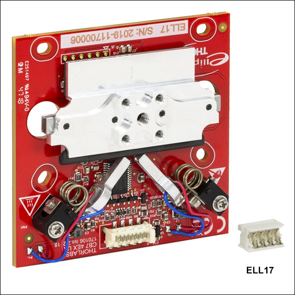
ELL17
Linear Stage (Also Available as Part of a Bundle)
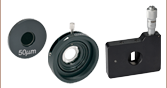
Application Idea
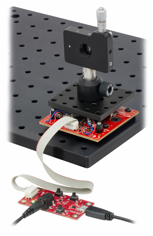
The ELL17K Linear Stage Kit positions the slit to spatially filter incident light.
Direction of Travel
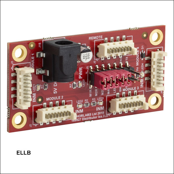
ELLB
Bus Distributor


Please Wait
| Key Specificationsa | |
|---|---|
| Travel | 28 mm (1.1") |
| Positioning Accuracy | 50 µm |
| Homing Accuracy | 20 µm |
| Repeatability (100 g Load) | 20 µm |
| Velocity (Maximum, No Load) | 180 mm/s |
| Maximum Total Load | 200 g (7.1 oz) |
| DC Voltage Input | 4.5 to 5.5 V |
| Minimum Lifetimeb | 100 km of Travel |
| Weight of Stage and Bracket | 76 g (2.7 oz) |
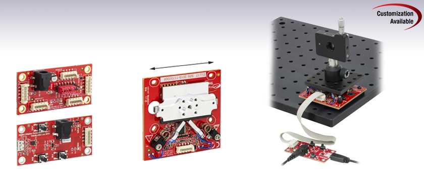
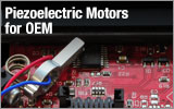 Figure 1.1 Thorlabs' Elliptec Technology for OEM
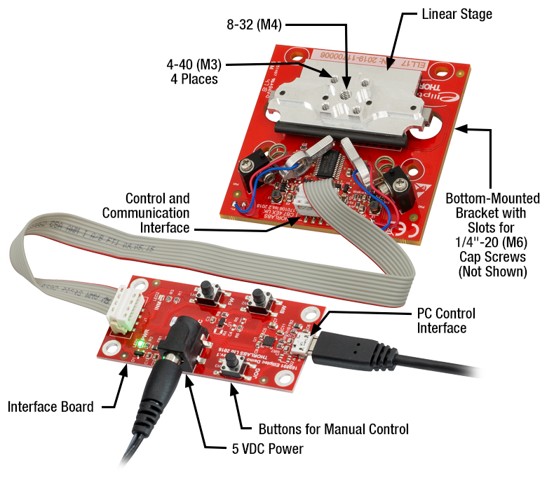
Click to Enlarge
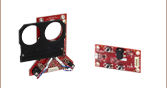
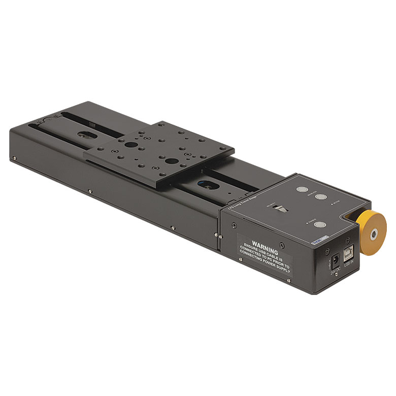
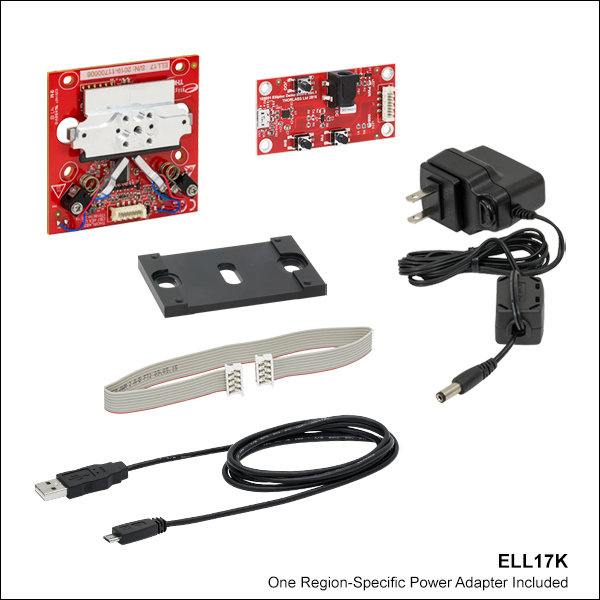
Figure 1.2 The components of the ELL17K(/M) linear stage bundle are shown connected and with key features labeled.
Features
- Ideal for OEMs and Applications Requiring Rapid, Precise Positioning
- Micro-B USB and Picoflex®1 Connectors for Control Signals
- Multi-Drop Serial Communication Protocol Supported
- Linear Stage with One 8-32 (M4) and Four 4-40 (M3) Tapped Holes
- Magnetic Incremental Linear Encoder Used to Position Stage
- Bus Distributor Facilitates Control of Up to Four Elliptec® Devices
- Accessory Upgrade Kits, Additional Interface Boards, and Cables Available Below
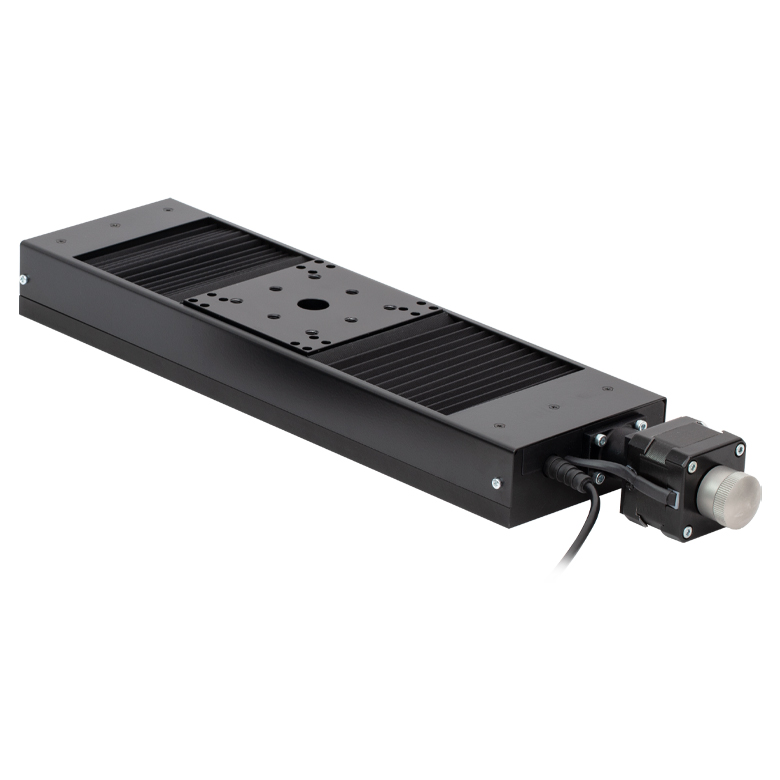
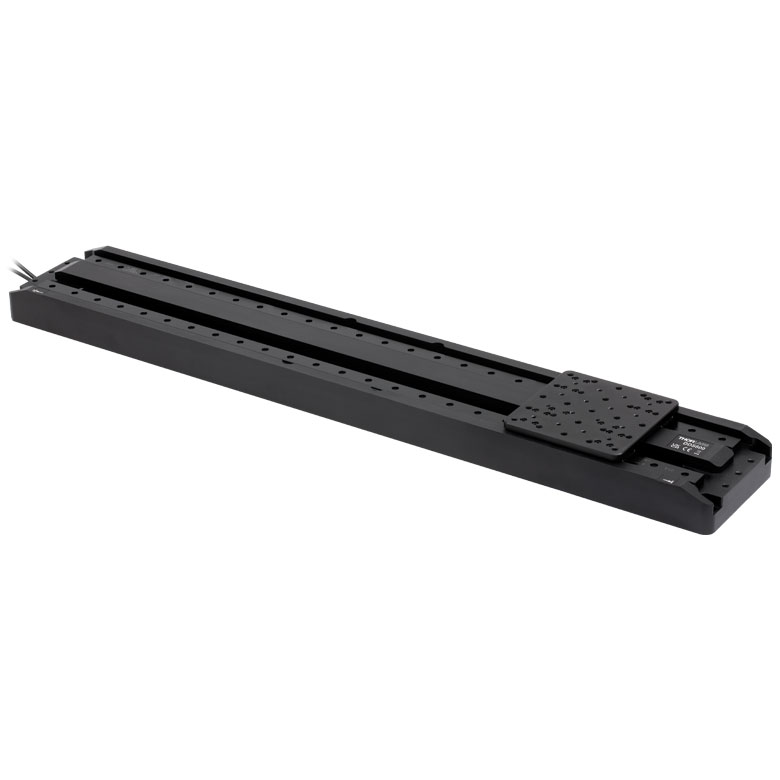
Driven by Thorlabs' Elliptec piezoelectric resonant motor technology, this linear stage is designed to be a compact solution for OEM applications requiring linear movement. The linear stage is offered as a standalone unit (Item #'s ELL17 and ELL17/M), or as part of a bundle (Item #'s ELL17K and ELL17K/M), which also contains an ELLC interface board for manual control of the stage, mounting brackets, power supply, and cables for connecting the stage and interface board to each other and to a PC. Thorlabs also offers the ELLC1 and ELLC2 Accessory Packs which can be used to upgrade standalone units to kits. Please note that the ELLC1 and ELLC2 Accessory Packs do not include the brackets used in the ELL17K(/M) bundle.
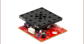
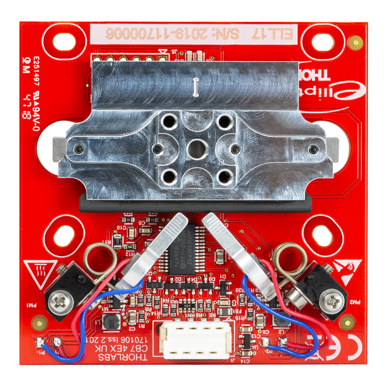
Each stage has one center 8-32 (M4) tapped hole for attaching a single component and the four 4-40 (M3) tapped holes may be used to secure an adapter plate, such as the MMP1(/M) or RB13P1(/M).The stage is lightweight and compact with a mass of 52 g and footprint of 68.0 mm x 67.0 mm when the stage is centered. The full travel range of the stage requires 7.5 mm of clearance on either side. The closed-loop operation allows the translating platform to be positioned with an accuracy of 100 µm and a repeatability of 60 µm. The assembled components of the ELL17K(/M) are shown in Figure 1.2, with key features labeled.
The motor is highly dynamic and has no gearing. The tips of both motor housings are in firm contact with the plastic track at the base of stage, as can be seen in Figure 1.2. The motors are installed with opposite orientations and translation in both directions occurs when one motor pushes the track forward while the other pulls it backward. The linear stage is not designed for continuous operation. We recommend operation with duty cycles of 40% or less. When power is not applied to the motors, the stage is held in place by an approximately 1 N combined force exerted by the stationary arms of the motors. Please see The Elliptec® Motor tab for more information.
The open frame format, simplicity, and adaptability of this linear stage make it attractive for OEM applications, as it can be customized according to customer requirements and produced in high-volume quantities. Please contact us to discuss your specific requirements so that we may tailor a solution to meet the needs of your application.
Control
There are multiple options for powering, driving, and controlling this stage, which are detailed in the Positioning the Linear Stage section of the Operation tab. The stage possesses a 3.3 V serial bus and is designed to be operated with or without the ELLC interface board; the Pin Diagram tab provides pin assignments. Thorlabs offers software for our Elliptec products capable of providing full and independent control of the stage. When the interface board is used as an accessory to change the position of the stage, its status in the software is automatically updated.
| Elliptec Resonant Motor Products | |||||||
|---|---|---|---|---|---|---|---|
 |
 |
 |
 |
 |
 |
 |
 |
| Multi-Position Sliders |
28 mm Linear Stage |
60 mm Linear Stage |
Rotation Stage |
Ø1/2" Rotation Mount |
Ø1" Rotation Mount |
Ø2" Rotation Mount |
Motorized Irises |
Multiple Elliptec devices can be controlled using the ELLB Bus Distributor or by splicing multiple connectors onto one ribbon cable. A single bus distributor can connect up to four Elliptec devices; up to 16 devices can be connected if the buses are daisy chained. This bus can be controlled one of three ways: through an ELLC interface board (included with the bundles below; also available separately) to connect to a PC running the Elliptec software, by connecting to an Arduino®2 or Raspberry Pi®3 board, or by wiring the connector pins to a user-supplied control board. Alternatively, up to 16 devices can be spliced onto a single ribbon cord. The devices can then be simultaneously controlled by the interface board or selectively controlled by the Elliptec software. See the manual for instruction on how to splice multiple devices onto a ribbon cord and the Pin Diagrams tab for pin assignments when making custom connections.
- Picoflex is a registered trademark of Molex Incorporated.
- Arduino is a registered trademark of Arduino Sa Société Anonym (SA).
- Raspberry Pi is a registered trademark of the Raspberry Pi Foundation.
| Specificationsa | |
|---|---|
| Performance | |
| Travel | 28.0 mm (1.1") |
| Positioning Accuracy | 50 µm |
| Homing Accuracy | 20 µm |
| Repeatability (With 100 g Load) | 20 µm |
| Velocity (Maximum, No Load) | 180 mm/s |
| Acceleration (Maximum, No Load) | 6.0 m/s2 |
| Minimum Holding Force (Both Motors Engaged) | 1 N |
| Vertical Straightness (Runout)b | 10.0 µm |
| Horizontal Straightness (Runout)b | 10.0 µm |
| Pitch (Over Full Travel Range) | 2.4 mrad |
| Yaw (Over Full Travel Range) | 2.4 mrad |
| Full-Scale Nonlinearity Error | <120 µm |
| Encoder Resolution | 0.98 µm |
| Velocity Compensation (No Load)c | 60% to 100% |
| Maximum Total Loadd | 200 g (7.1 oz) |
| Minimum Lifetimee | 100 km of Travel |
| Electrical | |
| Motor Type | Elliptec® Resonant Piezo |
| DC Voltage Input | 4.5 to 5.5 V |
| Typical Current Consumption During Movement (No Load) |
0.90 A |
| Typical Current Consumption During Standby | 0.07 A |
| Communications | |
| Busf | Multi-Drop 3.3 V/5 V TTL RS232 |
| Connector on Linear Stage Board | Picoflex® |
| Connectors on Interface Board | Picoflex® Micro-B USB 5 VDC Power: [For Plug with Ø5.5 mm OD (Ground) and Ø2.1 mm ID (+5 V)] |
| Speed | 9600 baud |
| Data Length (1 Stop Bit, No Parity) | 8 bit |
| Protocol Data Format | ASCII HEX |
| Module Address and Command Format | Mnemonic Character |
| 8-Conductor Ribbon Cable Length (Supplied) | 0.250 m |
| 8-Conductor Ribbon Cable Length (Maximum) | 3 m |
| Mechanical | |
| Mounting Threads (On Stage) | One 8-32 (M4), Four 4-40 (M3) Depth: 4 mm (0.16") |
| Dimensions of the Linear Stage Board (Without Bracket) |
68.0 x 67.0 x 15.3 mm (2.68" x 2.64" x 0.60") |
| Dimensions of the Linear Stage Board (With Bracket) |
68.0 x 67.0 x 18.4 mm (2.68" x 2.64" x 0.73") |
| Dimensions of the Interface Board | 32.0 mm x 66.0 mm x 12.5 mm (1.26" x 2.60" x 0.49") |
| Weight of the Linear Stage Board (Without Bracket) | 52 g (1.8 oz) |
| Weight of the Linear Stage Board (With Bracket) | 76 g (2.7 oz) |
| Environmental Operating Conditions | |
| Temperature Range | 15 to 40 °C (59 to 104 °F) |
| Maximum Relative Humidity (Non-Condensing) | <80% at 31 °C |
| Maximum Altitude | 2000 m |
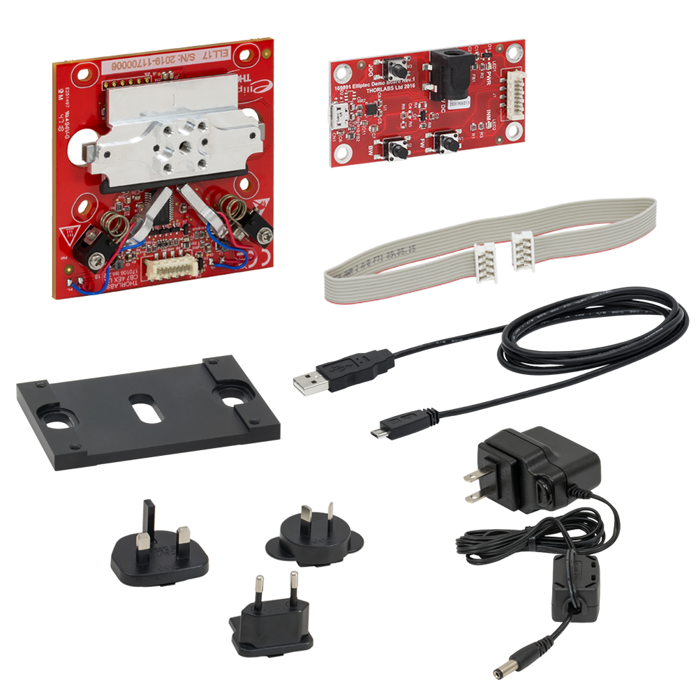
Click to Enlarge
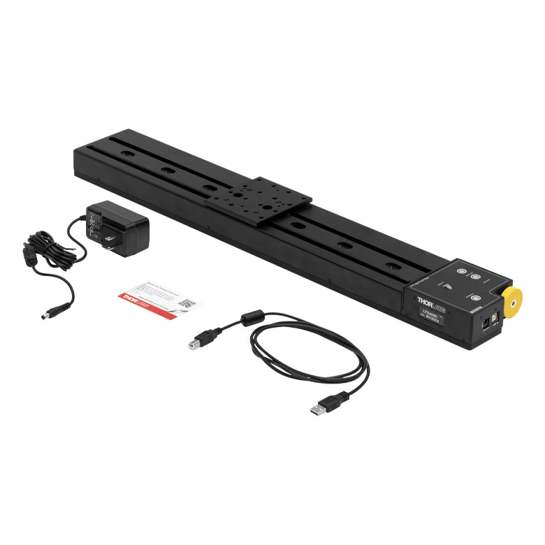
Figure 2.1 Components of the ELL17K(/M) Bundle
(One Region-Specific Power Adapter Included with the Power Supply)
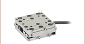
As shown in Figure 2.1, a mounting bracket is included with the bundle. The bracket fastens to the underside of the linear stage's PCB with the four included screws. Two slots in the bracket align with the Ø11.0 mm (Ø0.43") holes at either side of the PCB, so that 1/4"-20 (M6) cap screws can be inserted through the holes in the PCB to secure the linear stage board to optical tables and breadboards. The bracket adds 5.0 mm of thickness to the profile of the stage. Figure 2.2 shows the dimensions and mounting features of the stage itself.
Click to Enlarge
Figure 2.2 Mechanical Drawing of the Linear Stage
Click to Enlarge
Figure 2.3 Mechanical Drawing of the ELLC Interface Board
| Connector J1 Pinouta,b | ||
|---|---|---|
| Pin | Type | Function |
| 1 | PWR | Ground |
| 2 | OUT | ODTX - Open Drain, Transmit 3.3 V TTL RS232 |
| 3 | IN | RX Receive - 3.3 V TTL RS232 |
| 4 | OUT | In Motion, Open Drain, Active Low, Max 5 mA |
| 5 | IN | JOG/Mode, Active Low, Max 5 V |
| 6 | IN | BW Backward, Active Low, Max 5 V |
| 7 | IN | FW Forward, Active Low, Max 5 V |
| 8 | PWR | VCC +5 V ± 10%; 900 mA |
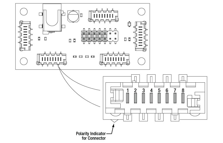
Click to Enlarge
Figure 3.1 Pinout diagram of the Picoflex® connector is shown referended to a partial diagram of the Linear Stage Board. The polarity indicator on the connector must be adjacent to the red wire on the supplied 8-connector cable.
| ELLB Connector J1, J2, J3, and J4 Pinouta,b | ||
|---|---|---|
| Pin | Type | Function |
| 1 | PWR | Ground |
| 2 | OUT | ODTX - Open Drain, Transmit 3.3 V TTL RS232 |
| 3 | IN | RX Receive - 3.3 V TTL RS232 |
| 4 | OUT | In Motion, Open Drain, Active Low, Max 5 mA |
| 5 | IN | Not Connected |
| 6 | IN | Not Connected |
| 7 | IN | Not Connected |
| 8 | PWR | VCC +5 V ± 10%; 800 mA per Connected Device |
Click to Enlarge
Figure 3.2 Pinout diagram of the Picoflex® connector is shown referenced to a simplified diagram of the ELLB Bus Distributor. The polarity indicator on the connector must be adjacent to the red wire on the supplied 8-connector cables.
Operation Notes
This tab contains information on handling, mounting, and operating the ELL17K(/M) Linear Stage Bundle.
Contents- Handling
- Mounting and Loading the Linear Stage
- Supplying Power
- Operation of the Motors
- Homing the Linear Stage
- Positioning the Linear Stage
- Resonant Frequencies

Click to Enlarge
Figure 4.1 The Linear Stage Board with Adapter Plate RB13P1 Mounted to the Top of the Stage
Click to Enlarge
Figure 4.3 The Linear Stage (Without the Bracket)
Click to Enlarge
Figure 4.2 Features of the Linear Stage
Click to Enlarge
Figure 4.5 The ELLC Interface Board
Click to Enlarge
Figure 4.4 Features of the ELLC Interface Board
Handling
The linear stage and interface board included in the ELL17K(/M) bundle are robust to general handling. To ensure reliable operation, keep the surface of the plastic track contacted by the motors free of oils, dirt, and dust. It is not necessary to wear gloves while handling the linear stage, but avoid touching the track to keep it free of oils from fingerprints. If it is necessary to clean the track, it may be wiped with isopropyl alcohol or mineral spirits (white spirit). Do not use acetone, as this solvent will damage the plastic track.
The open frame format of the ELL17(/M) stage can tolerate up to 8 kV of static discharge. ESD precautions should be taken, as an electrostatic discharge can produce an electrical signal that may cause unintended movement of the stage. A bending load in excess of 500 g applied to the board may cause the PCB to deform, which will degrade the performance of the linear stage. As readings from a magnetic sensor are used during the homing and positioning of the stage, avoid subjecting the structural PCB to excessive loads or magnetic fields. Limit the strength of magnetic fields in proximity to the magnetic sensor to ±5 mT to avoid negatively affecting the homing and positioning operations.
Mounting and Loading the Linear Stage
The linear stage can be operated with the top surface of the stage in the horizontal or the vertical plane. If the latter is chosen, orient the stage so that it moves side to side rather than up and down. A mounting bracket included with the ELL17K(/M) fastens to the underside of the linear stage's PCB with the four included screws. Two slots in the bracket align with the Ø11.0 mm (Ø0.43") holes at either side of the PCB, so that 1/4"-20 (M6) cap screws can be inserted through the holes in the PCB to secure the linear stage to an optical table or breadboard. Alternately, the bracket can be omitted and the four slotted holes in the PCB used to attach the stage to a custom fixture. Ensure that electrically conductive structures are not in contact with the back of the board, as this may cause electrical shorts detrimental to the operation of the stage. When mounting the stage, ensure that the installation does not bend the PCB.
Loads may be mounted to the stage using the 8-32 (M4) or four 4-40 (M3) tapped holes at the center. The spacing of the 4-40 (M3) tapped holes is designed to be compatible with adapter plates such as the MMP1(/M) and RB13P1(/M), as shown in Figure 4.1. The maximum allowed weight of the mounted components is 200 g. In all cases of mounting and loading, ensure that nothing interferes with the moving parts of the linear stage and that the stage and its load are securely fastened to prevent jostling during movement. Jostling of the stage or the load can cause an encoder error.
Supplying Power
When the setup includes the interface board, power may be supplied through the Micro-B USB connector and/or the 5 VDC power socket located on the board. The electronics on the interface board convert the applied DC signal to a sinusoidal signal oscillating at the required resonance frequency.
The ELL17K(/M) bundle includes a 5 VDC power supply whose connector mates with the power socket on the interface board. Delivering power through this socket also allows the Micro-B USB connector to be used for a computer to control the stage remotely. The power supplied by a computer through the USB 2.0 connection is not sufficient to power the stage. If computer control is not necessary, another option for supplying power to the stage is a portable USB 5 V battery pack connected to the Micro-B USB connector on the interface board.
When the implementation does not include the interface board, the connection with the power source is made using the pins on the Picoflex® connector that is included on the linear stage board. A pinout diagram of this connector is included in the Pin Diagram tab, and information on powering and addressing the linear stage is given in the manual and the communications protocol manual, respectively.
Operation of the Motors
The motion of the linear stage is controlled by forcing the piezoelectric elements to vibrate at specific ultrasonic frequencies. For each motor, there is an ultrasonic resonant frequency that will push the stage forward, and another that will pull the stage backward. Operating a motor at one of its resonance frequencies causes the tip of the motor to continuously cycle in a tight clockwise elliptical path. When the motor is driven at its other resonant frequency, the tip of the motor cycles through that same path in a counterclockwise direction. Both resonant frequencies are around 100 kHz. The total displacement at the tip of the motor is a function of the mechanical load it is driving and the voltage supplied to the piezo element. In the case of no loading and a 5 V maximum driving voltage at a resonant frequency, the tip of the motor expands and contracts by no more than a few microns while tracing the elliptical path. Please see The Elliptec® Motor tab for more information and an animation illustrating the operational principle of the motors.
Homing the Linear Stage
To Home the stage, press the BW button on the interface board, click the Home button in the Elliptec® software's graphical user interface (GUI), or send the appropriate ASCII message as is specified in the communications protocol manual. The stage uses a relative (incremental) magnetic sensor with an encoder resolution of 0.98 µm to home and position the stage. During the procedure to define the default Home position, the stage is translated forward and backward to index the limits of travel. The default Home position is located at the backward limit of the stage's range of motion. If desired, the user may redefine the position of Home to be offset from the default position. Being able to customize the Home position can be useful when synchronizing the orientations of two or more stages.
Positioning the Linear Stage
Note that the linear stage is not intended for continuous operation. We recommend operation with duty cycles of less than 40% during general use, while operation with duty cycles greater than 60% should be limited to a few seconds.
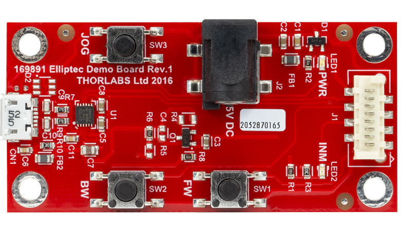
Before the stage may be positioned, the Home position of the stage must be found. Please see the previous section for details. The movement of the stage may be controlled by pressing buttons on the interface board, through computer control via the Elliptec software package that may be downloaded, or by sending simple signals to digital lines on the stage's board. The buttons on the interface board can be seen in Figure 4.5. A link to download the software and accompanying documentation can be found in the Software tab. The interface board may be used as an accessory while interfacing with the stage through the Elliptec software; all changes in the position of the linear stage that occur as a result of pressing buttons on the interface board are registered by the software, and the software may independently control the linear stage while the interface board is connected.
Multiple Elliptec devices can be be controlled using the ELLB Bus Distributor or by splicing multiple connectors onto one ribbon cable. A single bus distributor can connect up to four Elliptec devices; up to 16 devices can be connected if the buses are daisy chained. This bus can be controlled one of three ways: through an interface board (included with the bundles below; also available separately) to connect to a PC running the Elliptec software, by connecting to an Arduino® or Raspberry Pi® board, or by wiring the connector pins to a user-supplied control board. Note that if an interface board is used, its on-unit buttons will be disabled. Alternatively, up to 16 devices can be spliced onto a single ribbon cord. The devices can then be simultaneously controlled by the interface board or selectively controlled by the Elliptec software. See the manual for instruction on how to splice multiple devices onto a ribbon cord and the Pin Diagrams tab for pin assignments when making custom connections. The communications protocol manual describes how to use the software to individually address each connected device. A link to download the software and accompanying documentation can be found in the Software tab.
The interface board can be used to move the stage forward and backward in increments by pressing and holding the JOG button while pressing and releasing the FW or BW button, respectively. The default increment is 2 mm, and a custom step size can be set using the Elliptec software or by sending the appropriate ASCII message(s) as specified in the communications protocol manual. The Elliptec software can be used to move the stage to absolute and relative positions, in addition to jogging the stage forward or backward. The software is also used to set the jog step size, read the position of the stage, and adjust the position of Home, as is described in the previous section. The velocity of the stage can be adjusted to a value equal to or greater than 60% of the maximum velocity through use of the ASCII message calls described in the communications protocol manual.
The stage learns to efficiently position itself precisely using a position error compensation algorithm. After the stage moves into a new position, it detects the error between the requested and actual positions. The position of the stage is then corrected, and an error compensation value is calculated. The algorithm is then updated with the error compensation value, so that it is applied when the stage is move to its next position. Typically, an optimum error compensation value is found after between two and six movements.
Resonant Frequencies
On power-up, the factory default setting instructs each motor driving the linear stage to search for the resonant frequencies that will deliver the best performance. During this process, the linear stage will translate forward and backward. If movement on start-up is undesirable, it is possible to disable this calibration procedure by using the serial port to initialize the frequencies on power-up. A new search for optimal resonant frequencies may be performed at any time; to maintain optimal performance, it is recommended that new searches be performed after changes in loading and/or ambient temperature. Please see the manual for details.
Click to Enlarge
Figure 81B The Components of the Elliptec Motor
Click to Enlarge
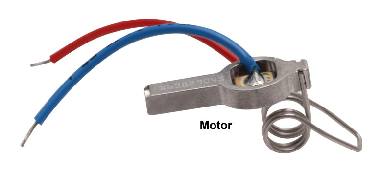
Figure 81A The Elliptec Piezoelectric Resonant Motor
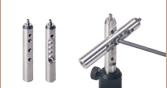
The Elliptec® Piezoelectric Resonant Motor
Thorlabs' Elliptec® piezo resonant motor, shown in Figure 81A, is lightweight, with a mass of 1.2 g, and compact: the dimensions of the resonator housing, excluding the spring, are 8 mm x 4 mm x 20 mm.
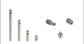
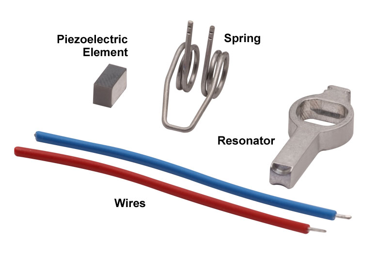
Components of the Motor
The components that compose the motor are shown in Figure 81B. The piezoelectric element is press fit into the aluminum resonator, which has been precisely designed and machined to produce the desired elliptical motion at the tip and to interface optimally with the driven module. The free ends of the spring are integrated with the resonator housing. The wires, which are soldered to the top and bottom of the piezoelectric element, deliver the voltage signal that induces the piezoelectric element to vibrate at ultrasonic frequencies.
When the motor is built into a system, the open loop of the spring is bolted to a sturdy surface that is stationary with respect to the item to be driven, and the tip of the resonator is placed in contact with the item. The purpose of the spring is to maintain constant contact between the tip of the resonator and the driven item, and the direction of motion is determined by the resonance frequency at which the piezo element is driven.
Elliptical Motion and Comparison with Conventional Motors
The motor is operated by driving it at one of its two resonance frequencies. A voltage signal oscillating at an ultrasonic frequency is applied to the piezoelectric chip, which responds by expanding less than a micron and then contracting back to its original dimensions at the frequency of the driving signal. This rapid-cycling change in the chip's dimensions causes a vibration in the aluminum resonator housing. When the vibration is at one of the housing's resonance frequencies, a pushing motion results at the tip of the motor. When the vibration is at the other resonance frequency a pulling motion results.
As illustrated in Video 81C, the pulling and pushing motions result from the tip of the motor tracing an elliptical path in space when the motor operates at resonance. The selected resonance frequency controls the direction of the cyclical motion. The motor's tip traces one half of the ellipse as it expands and the other half as it contracts. When the motor pushes the driven item, the motor's tip is in contact with the item while the tip expands; the two are not in contact while the tip contracts. The converse is true when the motor pulls the driven item in the opposite direction. The total displacement at the tip of the motor is a function of both the mechanical load it is driving and the voltage supplied to the piezo element. The maximum displacement can be up to a few microns when the peak driving voltage is 5 V.
The motor behaves in many ways like a DC or electromagnetic stepper motor, but it does not suffer from many of the drawbacks of these conventional motors. Unlike conventional electromagnetic motors, which must overcome inertial delays to come to a stop, the highly dynamic Elliptec motor can stop within microseconds. As it has no gears, it does not exhibit backlash. Since it possesses no magnets, it is compatible with use in environments sensitive to electromagnetic interference. The motion of the driven element is continuous and smooth. As the tip of the motor must be in contact with the driven item to induce motion, the motor possesses the safety feature of an inherent friction brake. When in contact with a plastic surface, the motor operates virtually silently.
For OEM applications, the motor can be manufactured in volume at low cost, and it can be driven by inexpensive analog electronics. It does not require microprocessors or software; however it is compatible for use with them.
Click to Enlarge
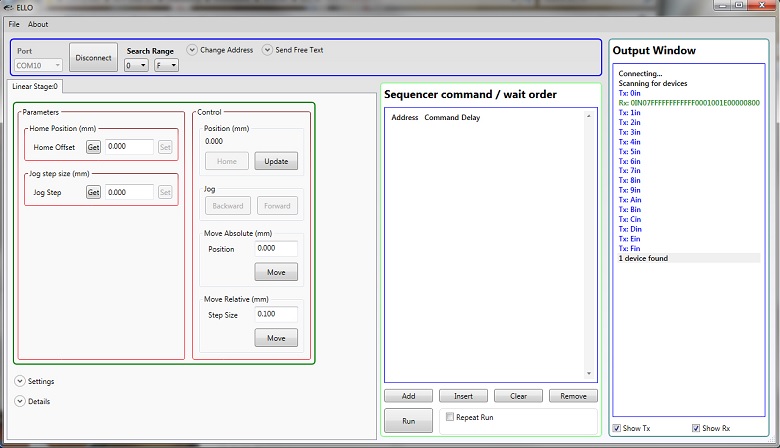
Figure 6.1 The Elliptec Piezoelectric Resonant Motor Control Software GUI
Software for Devices Driven by Elliptec® Piezoelectric Resonant Motors
All devices based on the Elliptec® resonant piezo motor may be controlled by the Elliptec system software, which features an intuitive graphical user interface (GUI). The source code, in C# format, is included in software bundle available for download, and custom applications can be created in any language. Figure 6.1 shows a screen capture of the GUI, and the button that follows links to the download page.
Commands are entered in the Sequencer command / wait order section located at the center-left of the GUI. An example of a sequence of commands that might be sent to the device is "Agj" to get the jog step size of the stage at address "A," "Asj0000200" to set the jog step size as 0.25 mm, and "Abw" to jog the stage at address "A" backward by 0.25 mm. The command "As1" is used to perform the frequency search that will identify the optimal resonant frequencies, for the current operating conditions, for Motor 1 at adddress "A."
Software
Version 1.6.6 (October 17, 2025)
Includes the Elliptec System Software, with an easy-to-use GUI. Also available for download is the Communications Protocol manual, which details the communication commands for the Elliptec software package.
| Posted Comments: | |
David D
(posted 2025-02-18 15:36:42.737) How can we create a reference for the ELLODevicePort in labview and correctly assign a com port? The .dll library doesn't have constructors for that element, and it's unclear how we should attempt to connect or change this parameter in the .net constructors that are available (Devices/Device/etc). The attached help files do not assist with this issue.
Could you please send example VIs for connecting to the instrument? dnewnham
(posted 2025-03-04 05:54:41.0) Thank you for your inquiry I will reach out to you directly to discuss your application SH Park
(posted 2024-12-12 11:24:26.687) Hello, I'd like to control ELL17 stage. The stage operates well; however, when initializing after power-on, the movement to the home position is too fast, causing it to hit the stopper with significant force. This impact results in alignment issues, so we are looking for a way to minimize the impact. Your assistance would be greatly appreciated. tschofield
(posted 2025-01-07 04:49:35.0) Thank you for reaching out. Unfortunately, the velocity of this stage cannot be directly controlled, not even during homing. I've reached out to you directly to discuss possible solutions further. user
(posted 2024-10-23 10:40:40.64) Hi,
I saw someone else asked this as well. I'm moving an adjustable slit mounted on the linear ELL17 stage and I was wondering if it would be possible to increase the rate at which the stage jogs beyond 2 Hz? I'd still like the stage to use the closed loop control since I want the position to be as accurate as possible. This is if I understood the closed loop control correctly? Thanks in advance for your help! spolineni
(posted 2024-10-28 07:35:55.0) Thank you for your inquiry. The frequency of jog depends on several factors specific to your setup. I’ll reach out to you personally to discuss your requirements in detail and help optimize your configuration. Sven zur Oven-Krockhaus
(posted 2024-04-26 11:57:28.917) Hello there,
I'd like to control the ELL17/M and ELL6 by writing a Labview routine, coupling their movement to buttons/sticks of a controller pad.
I'm running a Labview 32-bit version on a Windows 64-bit platform, so I assume that this is the reason I could not get the .dll files to work so far. Could this be set this up, e.g., via an Arduino board and serial communication? In any case, I guess I also need the ELLB to control both the ELL17/M and ELL6 in that way, correct?
Thanks in advance! do'neill
(posted 2024-05-10 09:30:57.0) Thank you for your response. You are right you can not use the 64bit dlls with 32 for 64bit LabVIEW. You also can not download the 32bit version on a 64bit computer. Using serial commands would be a way for you to still control the devices. Also using the ELLB is one of the ways to control both devices at the same time. I will reach out to you to discuss this in more detail. Valkyrie Jacobs
(posted 2024-03-25 07:00:09.58) Hey there,
When operating the stage, there are noises when it moves and I just want to make sure that this is normal?
Secondly, I would like to slow down the velocity of the stage, I'm looking at the source code and can't find the code to change this. I see there is a previous post on this:
"The velocity is way too fast, even with 200g load on it. And when I try to slow down the velocity (by sending "AsvXX"), the motor stopped working. How can I slow down the velocity to 12mm/s or 25mm/s?", so I'm assuming it is somewhere and I'm just missing it?
I'm quite new to this and your help would be appreciated.
Thanks in advance! cwright
(posted 2024-04-03 08:36:17.0) Response from Charles at Thorlabs: Thank you for contacting us. The velocity of the stage is not directly controllable as it is largely set by the resonance frequency of the piezo motors. The operating mechanism of this type of motor restricts how much control is possible over the velocity. The power of the stage is reduced slightly using the SV command, which will slow down the stage to an extent, and I will reach out to you to discuss its use. These stages should only make a little noise when in use so it is possible that there is dirt or oils (often from handling) on the black plastic track. This can cause the motors to slip and create additional noise. It should be cleaned using IPA and a lint free cloth. Gilles Pernot
(posted 2024-03-13 10:51:34.683) Hi, where can I find examples for the communications protocol for LabView? cstroud
(posted 2024-03-13 12:56:36.0) Thanks for reaching out. The available Elliptec commands can be found in the Thorlabs.Elliptec.ELLO_DLL help file, which is located in the Elliptec install folder. We also have a communications protocol. I will contact you directly to support your setup. user
(posted 2024-03-08 02:46:09.077) I recommend adding an address jumper on the PCB board. This feature proves to be quite useful when utilizing multiple devices through a single USB port. With the address jumper, there's no need to set the address for each device upon power-up, which significantly simplifies the control process. do'neill
(posted 2024-03-12 05:21:59.0) Thank you for reaching out and thank you for the feedback. I have passed on your suggestion our engineering teams to investigate for future development. User Ilya
(posted 2024-02-08 08:07:54.533) Everything is working fine. The only problem I have is that after I turn off and turn on the ELL 17/M Linear Translation Stage, the 'gp' function returns a negative position. The move to negative zone commands give the error "parameter out of range". To reset the current position, I need to send the command home 'ho'. But I can't send the command _HOSTREQ_HOME “ho” , it moves backwards all the way. In my product, such a move cannot be performed, there is no free space to exit to the "Home" position. Maybe there is a command to set the current position of the software, something like "_HOSTSET_POSITION" - set the current position of the specified motor. So I can restore last the current position after resetting the ELL17/M Linear Translation Stage. cstroud
(posted 2024-02-14 11:58:03.0) Thanks for reaching out. Unfortunately there is no way to change the current position value of the motor after start-up without homing the device. As "gp" returns a negative value, you will only be able to travel in the positive direction from the start point. You will need to home the device every time it is turned on. user
(posted 2024-01-29 11:56:16.86) Hi,
I just want to make sure I understand correctly;
I'm assuming since its accuracy is 50micrometers that 0.05m is the smallest step size?
Also
Jog - you have to click every time you want to move a step
Move Relative - moves relative from current position to next using step size
Move Absolute - moves from home to position given with no step size
So if I want the stage to move a step and then stop for a millisecond or so, I'll have to write a code to jog or move relative then stop and repeat?
Thanks in advance and sorry if its stupid questions :) spolineni
(posted 2024-02-06 06:42:12.0) Thanks for reaching out. You’ve correctly understood the Jog, Move Relative, and Move Absolute commands. The minimum step isn’t defined for this stage, but it’s lower bound would be 0.98µm. However, steps of this order would not be very precise or consistent. A 50µm step would be more reliable step. To make the stage move a step, pause, and repeat, you can either write a code or use the Kinesis GUI sequencer. I’ll contact you with more details soon. Eric van nuland
(posted 2023-06-01 02:59:30.113) Everything is working nice, the only problem I have is that after I send a move command it move directly but than I need to wait a second or so before ai can send a second move command. Why is this? can I speed this up. Would like to rotate the stage a degree or so 5 times per second. fguzman
(posted 2023-06-16 04:08:58.0) Thanks for you query. If you use the ELLO software, that is the standard pause time between commands. You may need to either tweak the code of the ELLO for your needs or create a short pi script or anything similar. Duty cycle should be of course in line with our recommendation. If you have any more questions please contact your local tech support team and we will be happy to help further. YenCheng Chao
(posted 2022-06-27 02:30:41.84) I try to use DIO moving the stage with a new jog step size . I can set a new value in software and move it. After remove USB cable and reset power, the jog is changed to default value. How to move with a new jog step by using DIO control? cwright
(posted 2022-06-27 05:00:11.0) Response from Charles at Thorlabs: Thank you for your query. You can persist the changes to the device by clicking the "Save User Data" option or sending the free text command 0us. Sam Rubin
(posted 2022-03-24 11:37:16.703) Hi,
I am looking to use this stage with a transmissive window, which i want to move right and left, and pass a beam through different parts of the window that way. So actually I am looking for something similar to the multi position slider, but without fixed stops. rather ability to stop it any where I want.
Is it possible to get a device customized for this?
Thanks
sam cwright
(posted 2022-03-25 06:14:28.0) Response from Charles at Thorlabs: Thank you for your query. Unfortunately we would not be able to offer a custom stage for small quantities. We would suggest using the ELL17 or ELL20 with an optic mount, such as LMR1/M or FMP1/M, fitted via the M4 thread. Gerard van Belle
(posted 2022-01-25 12:55:25.463) I'm a big fan of the ELL17 and related stages - simple, cheap. What I'm *not* a big fan of is the 950nm on-board light source that is completely undocumented. To have a mount for optics, which is probably going to be nearby sensitive optical detectors, have an optical light source (for its encoder? who knows?) that *isn't mentioned anywhere* is a Big Deal. We just lost a few nights on our 4.3-meter telescope because of a unknown light contamination which ultimately traced to these sliders inside an instrument. You don't want to know what time on a 4.3-m telescope costs.
On the plus side, we've made cute little 3D printed light shields for these stages. cdolbashian
(posted 2025-01-22 03:24:13.0) Thank you for bringing this to our attention. We apologize for the inconvenience with this, truly. We have included a callout in our manual which shares the existence of such an LED. Sang-Won Lee
(posted 2021-12-07 21:45:00.483) Could you support example codes with Visual Studio C++ ? YLohia
(posted 2021-12-23 12:28:15.0) Would you be looking to communicate via serial commands or the C# DLL with this? We have reached out to you directly to gather more information. Derlin Chow
(posted 2021-02-04 17:14:53.12) Hi,
I see the communication is via FT232, I assume that I can control it in linux PC? Am I right?
Thanks!
Derlin cwright
(posted 2021-02-05 06:59:45.0) Response from Charles at Thorlabs: Thank you for your query. Yes these devices can be controlled in Linux using the RS-232 interface Serial interface. The USB adapter uses a type FT232BM USB peripheral chip to communicate with the host PC but you can also connect directly to the Rx and Tx lines on the stage itself. The command protocol and communication parameters can be found at the following link: https://www.thorlabs.com/Software/Elliptec/Communications_Protocol/ELLx%20modules%20protocol%20manual.pdf Christoph Dresler
(posted 2020-02-24 08:30:53.727) Dear Thorlabs Team,
two technical question regarding the ELL17/M and the ELL6K motorized translation stages:
do you have measurements of the stages accuracy, when moving in small steps (preferably single encoder steps, meaning a few micrometer) in one direction over, for example, 200-400µm ?
Does that differ between the mentioned stages ?
Additionally: is it possible to hijack a port on the ELLB Bus distributor to run a photodiode ?
Yours sincerely,
Christoph Dresler AManickavasagam
(posted 2020-02-27 11:43:41.0) Response from Arunthathi at Thorlabs: Thanks for your query. Given the encoder resolution is 0.98 um and the Positional accuracy is 100 um you will not be able to control the device by single encoder steps as such steps will be close to the unit’s noise level. There will be no reliable motion achieved. In regards to using the BUS to run a photodiode if you are looking to power it up then it will be with Pin 1 and Pin 8 which are the 5V rails. If you would like to discuss your application further please contact your local tech support office. P: +49 (0) 8131-5956-2 E: Europe@thorlabs.com g.laliberte
(posted 2018-09-18 06:31:31.553) Hi,
We'd like to know if this has been tested at cryogenic temperature, and if it worked?
Best Regards
Gabriel Laliberte
Canada Research Chair in Quantum Microwave Radiation
Physics Department , Quantum Insitute,
Universite de Sherbrooke
2500 boul. de l'universite
Sherbrooke, Québec
Canada
J1K 2R1
819-821-8000 ext. 66489 AManickavasagam
(posted 2018-09-18 11:28:47.0) Response from Arunthathi @ Thorlabs: Thanks for your query. Unfortunately, these have not been tested at cryogenic temperature. At such condition the stage might be brittle (as the frame is plastic) and cease function. loven015
(posted 2018-06-11 09:40:50.453) Is it possible to change the units reported in the software from imperial to metric? We have the imperial board but would really prefer to measure in millimeters. AManickavasagam
(posted 2018-06-15 08:09:32.0) Response from Arunthathi at Thorlabs: Unfortunately, with an imperial board you will not be able to measure in millimeters. user
(posted 2018-06-05 18:37:56.14) The velocity is way too fast, even with 200g load on it. And when I try to slow down the velocity (by sending "AsvXX"), the motor stopped working. How can I slow down the velocity to 12mm/s or 25mm/s? rmiron
(posted 2018-06-06 04:48:20.0) Response from Radu at Thorlabs: Depending on the load, velocities less than 25% to 45% of max will likely cause the device to stall. Unfortunately, since 25mm/s corresponds to ~14% of the max velocity, I think you are probably unable to achieve those speeds using ELL7. matsk
(posted 2017-11-28 15:03:14.887) The bundled C# software don't compile.
Opening the ELLO solution in Visual Studio 2017, and trying to compile gives several errors.
Severity Code Description Project File Line Suppression State
Error CS2001 Source file 'P:\libs\elliptec\ELLO_DLL\ELLBaseDevice.cs' could not be found.
Error CS2001 Source file 'P:\libs\elliptec\ELLO_DLL\ELLPaddlePolariser.cs' could not be found.Active
Error CS0006 Metadata file 'P:\libs\elliptec\ELLO_DLL\bin\Debug\Thorlabs.Elliptec.ELLO_DLL.dll' could not be found ELLO_DLL_Test
Error The project file contains a property value that is not valid. ELLO
Error File 'Views\ELLPaddlePolariserView.xaml' cannot be found. ELLO
Error File 'Views\ELLPaddleView.xaml' cannot be found. ELLO
How can I use the product if i can't compile the source code?
Is there a simple C interface for this product?
Best regards,
tk bwood
(posted 2017-12-06 06:24:08.0) Response from Ben at Thorlabs: I am sorry to hear about your issues here. We will be in direct contact with you to troubleshoot this software issue. sergio.vilches
(posted 2017-09-14 12:28:12.74) It seems that the maximum rate at which the stage can be commanded to jog is about 2 Hz, either using the onboard switches or the serial interface.
Is there any way to improve this response time? For example, using the switches for open loop control, i.e. that the stage moves as long as the switch is actuated.
This would open new possibilities for this stage, for example, as part of a closed loop system. bhallewell
(posted 2017-09-18 10:07:27.0) Response from Ben at Thorlabs: Thank you for outlining your requirements. This will generally be dependent upon your application. I will contact you directly to get a discussion going. hthakur1611
(posted 2017-06-08 10:55:53.287) I have connected the interface board via USB and trying to find it with the Ello software. But it is saying 0 devices found. What can be the problem ? bwood
(posted 2017-06-08 09:54:26.0) Response from Ben at Thorlabs: I am sorry to hear about your difficulties here. I will contact you directly to discuss troubleshooting the device. In general, the best way to diagnose a USB issue is to swap USB cables, swap USB ports, and connect the device directly to the USB ports on the back of your computer. You can also open up device manager on your computer, and see if the USB device is present. ali
(posted 2017-04-19 17:07:48.403) The interface board provides the functionality of moving the stage in fixed steps forward or backward. Is that possible to move the stage to a specified absolute or relative position without using ELLO software? I want to have a standalone solution without the need of connecting the board to the computer. bhallewell
(posted 2017-05-10 10:13:56.0) Response from Ben at Thorlabs: Thank you for your question. It is not possible to persist a jog under two preset absolute positions & persist this outside of ELLO software. This is stored in volatile memory & so is lost on power cycle or software reset. gregor.anich
(posted 2016-12-01 09:15:14.627) I have multiple short questions:
1) As the device uses a magnetic sensor, can the positioning (home position) be affected by switching of magnetic fields nearby the device, even if the stage is not moved while switching fields? Or will external magnetic fields only interfere while the stage is moving?
2) Can excessive fields damage the sensor, or will they only confuse it?
3) I would need the stage to move a beam splitter into and out of a beam path. For this application only the homing position at one side of the travel is relevant. Could this be improved by adding some mechanical stop and just move the stage against that stop, or is that a bad idea? (Maybe you have another product better suited to my application?)
Thanks,
Gregor A. bwood
(posted 2016-12-05 10:17:46.0) Response from Ben at Thorlabs: Thank you for your questions, let me try and answer each of them in turn: 1) Magnetic fields should only affect the stage during homing. 2) We estimate it would table external magnetic fields in the Tesla range to begin to the impact performance of the device. 3) The stage already has mechanical stops, which are used in the normal function of the stage. If you are moving an optic in and out of the beam path, perhaps you could also consider the ELL6k. Although, the ELL6 may only be suitable for plate beamsplitters. florent.haiss
(posted 2016-10-29 11:15:09.923) Would it be possible to have a Labview example that controls absolute positioning and homing of the ELL7K.
Thanks. bhallewell
(posted 2016-11-16 09:50:14.0) Response from Ben at Thorlabs: Thank you for your question. We have just today released a new version of the ELLO Elliptec Control Software which includes a .dll with core code examples contained. This can be downloaded from the following web link.
https://www.thorlabs.com/software_pages/ViewSoftwarePage.cfm?Code=ELL ludoangot
(posted 2016-10-28 12:26:28.72) This is a very interesting concept and product. I have few questions: won't the plastic part in contact with the tip of the motor eventually wear? Given your magnetic position sensor has a 0.5um resolution, why can't more accurate homing and positioning be obtained? From releasing the communication protocol, it seems I should be able to write my own control software under linux, in such a case do I need the interface board? Finally do you offer an XY version of this stage, do you plan to offer it, or can one be made by simply assembling 2 linear stages? Thank you! bhallewell
(posted 2016-11-07 06:42:12.0) Response from Ben at Thorlabs: There will be some wear in the system however this is taken into account within the specified lifetime spec of our motion control stage (100 km of Travel). The force applied between the motor & rail will be dependent upon how the stage is loaded & fitted into your application. Drive force from the motor is altered during frequency optimisation & changes in temperature however overloading or continual use of the device can further affect this factor which will also contribute to wear.
The homing accuracy is a compromise between speed & accuracy when altering load between 0 & 200g. The resolution is that of the encoder whereas the accuracy is deduced from the optimised PWM elliptical motion of the motor.
You still need a TTL serial converter. The included handset is based on a FTDI chip which is generally supported by Linux.
Unfortunately we don’t provide an XY variant of this stage & there may be some limitations from resistive force from cabling & off-axis load if these were to be stacked. I will contact you directly to discuss this. |
Motorized Linear Translation Stages
Thorlabs' motorized linear translation stages are offered in a range of maximum travel distances, from a stage with 20 µm of piezo translation to our 600 mm direct drive stage. Many of these stages can be assembled in multi-axis configurations, providing XY or XYZ translation. For fiber coupling applications, please see our multi-axis stages, which offer finer adjustment than our standard motorized translation stages. In addition to motorized linear translation stages, we offer motorized rotation stages and goniometers. We also offer manual translation stages.
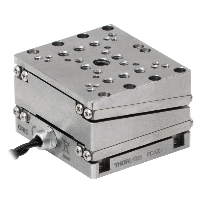
Piezo Stages
These stages incorporate piezoelectric elements in a variety of drive mechanisms. ORIC® stages incorporate piezo inertia drives that use "stick-slip" friction properties to obtain extended travel ranges. Our Nanoflex™ translation stages use standard piezo chips along with manual actuators. Elliptec® stages use resonant piezo motors to push and pull the moving platform through resonant elliptical motion. Our LPS710E z-axis stage features a mechanically amplified piezo design and includes a matched controller.
| Piezoelectric Stages | ||||||
|---|---|---|---|---|---|---|
| Product Family | ORIC® PDXZ1 Closed-Loop 4.5 mm Vertical Stage |
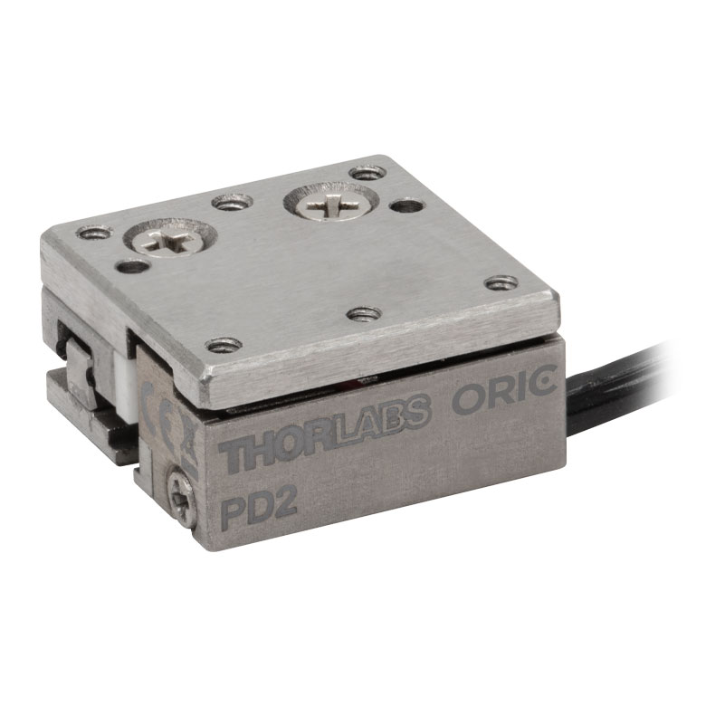
ORIC® PD2 Open-Loop 5 mm Stage |
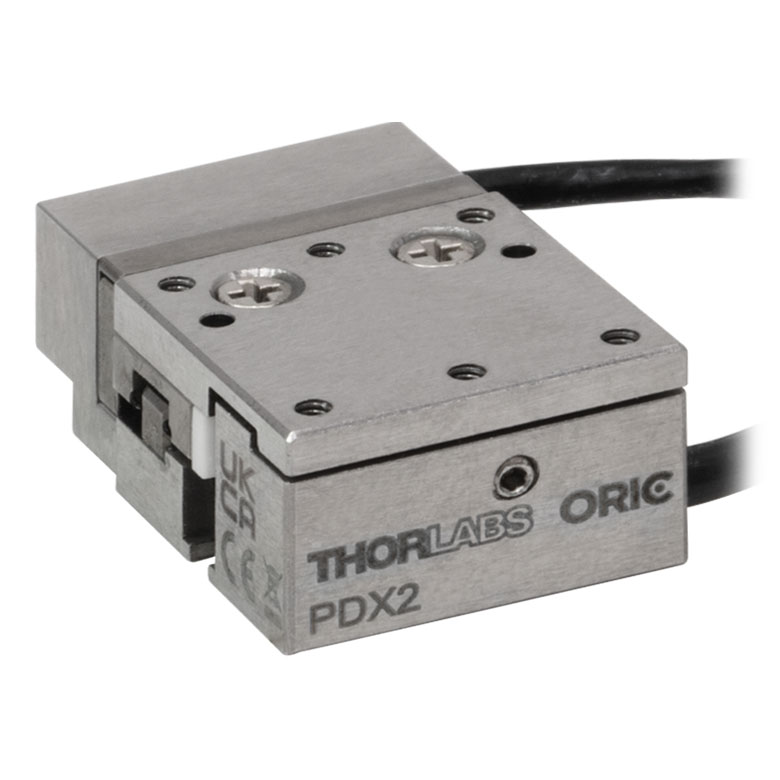
ORIC® PDX2 Closed-Loop 5 mm Stage |
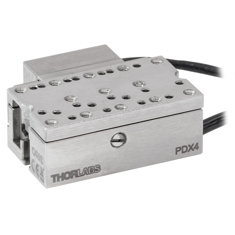
ORIC® PDX4 Closed-Loop 12 mm Stage |
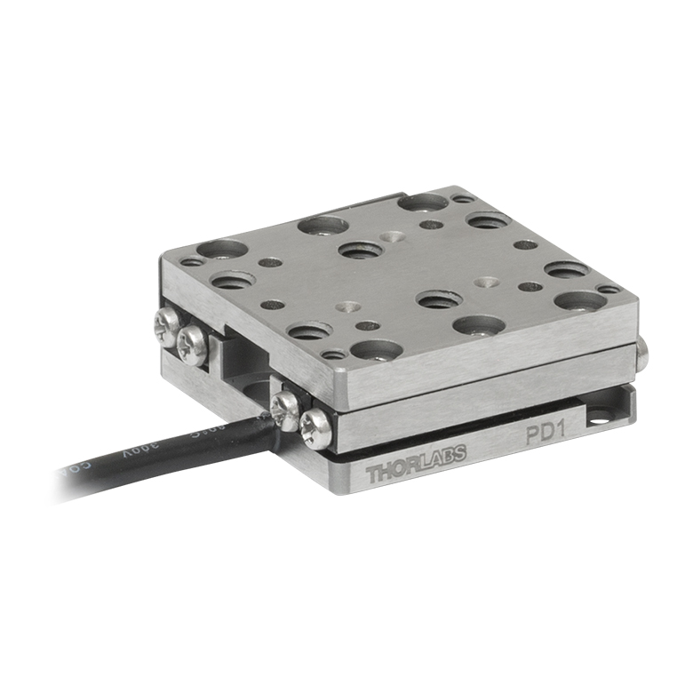
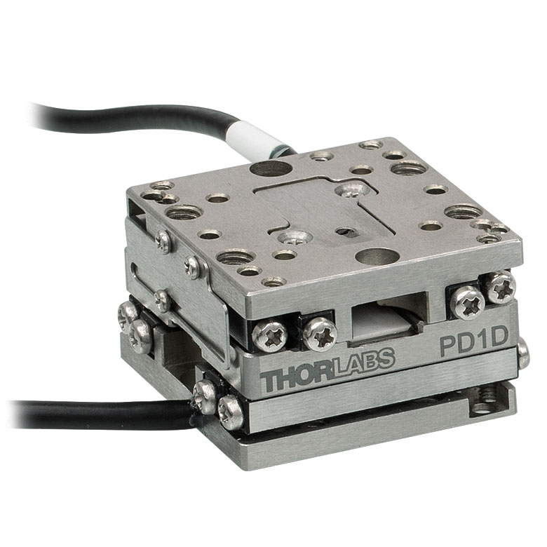
ORIC® PD1 Open-Loop 20 mm Stage |
ORIC® PD1D Open-Loop 20 mm Monolithic XY Stage |
| Click Photo to Enlarge |
 |
 |
 |
 |
 |
 |
| Travel | 4.5 mm | 5 mm | 12 mm | 20 mm | ||
| Speed | 1 mm/s (Typ.)a | 10 mm/s (Typ. Max)b | 8 mm/s (Typ.)c | 15 mm/s (Typ.)a,c | 3 mm/s (Typ. Max)d | |
| Drive Type | Piezoelectric Inertia Drive | |||||
| Possible Axis Configurations | Z | X, XY, XYZ | XY, XYZ | |||
| Mounting Surface Size |
45.0 mm x 42.0 mm | 13.0 mm x 13.0 mm | 13.0 mm x 23.0 mm | 30.0 mm x 30.0 mm | ||
| Additional Details | ||||||
| Piezoelectric Stages | ||||||
|---|---|---|---|---|---|---|
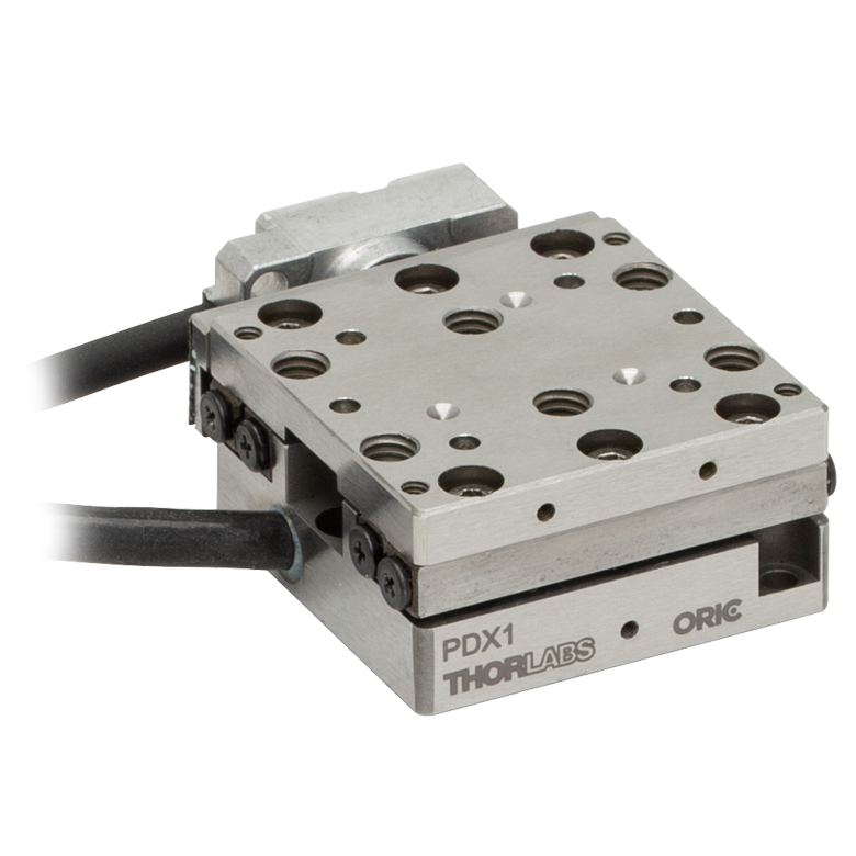
| Product Family | ORIC® PDX1 Closed-Loop 20 mm Stage |
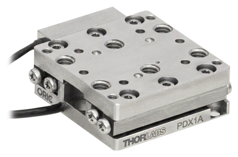
ORIC® PDX1A Closed-Loop 20 mm Stage Low-Profile |
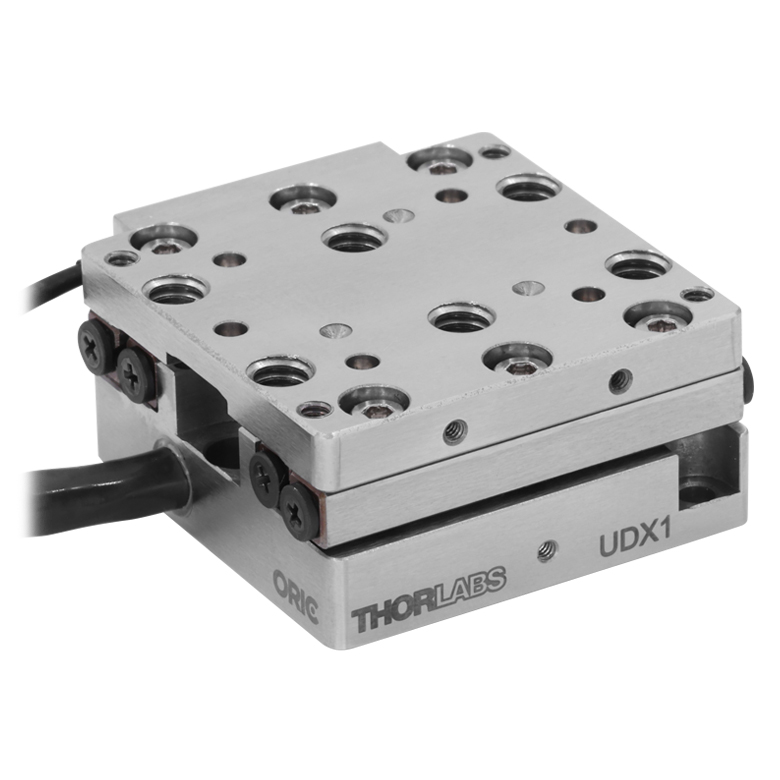
ORIC® UDX1 Ultrasonic Closed-Loop 20 mm Stage |
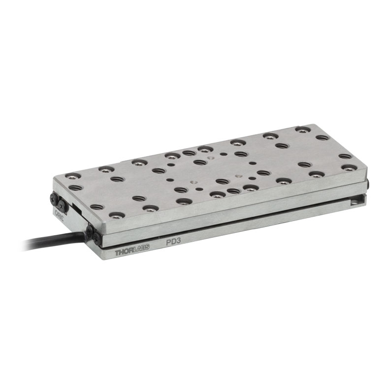
ORIC® PD3 Open-Loop 50 mm Stage |
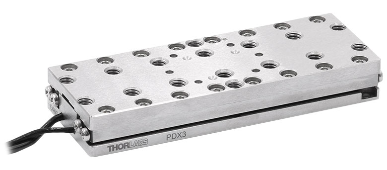
ORIC® PDX3 Closed-Loop 50 mm Stage |
|
| Click Photo to Enlarge |
 |
 |
 |
 |
 |
|
| Travel | 20 mm | 50 mm | ||||
| Speed | 20 mm/s (Typ. Max)a | 10 mm/s (Typ.)b | 100 mm/s (Typ. Max)c | 10 mm/sd | 10 mm/s (Typ. Max)b | |
| Drive Type | Piezoelectric Inertia Drive | Ultrasonic Piezoelectric Drive | Piezoelectric Inertia Drive | |||
| Possible Axis Configurations | X, XY, XYZ | |||||
| Mounting Surface Size |
30.0 mm x 30.0 mm | 80.0 mm x 30.0 mm | ||||
| Additional Details | ||||||
| Piezoelectric Stages | |||||||
|---|---|---|---|---|---|---|---|
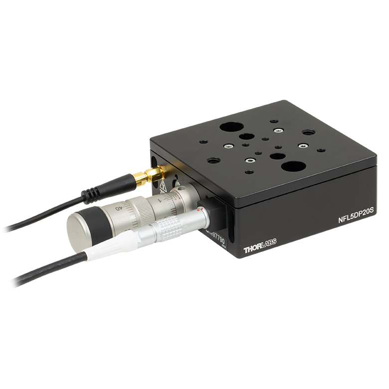
| Product Family | Nanoflex™ 20 µm Stage with 5 mm Actuator |
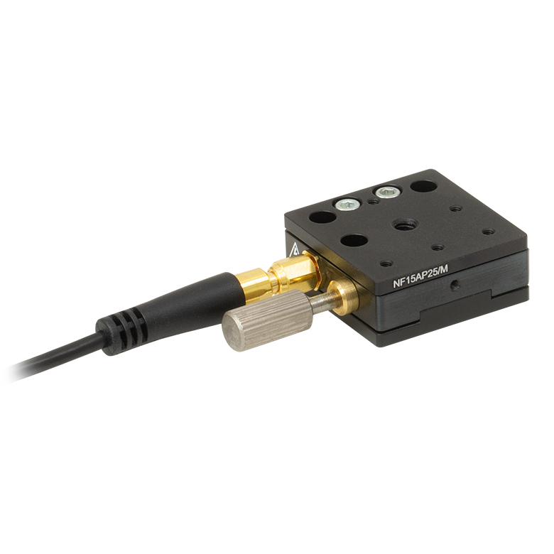
Nanoflex™ 25 µm Stage with 1.5 mm Actuator |
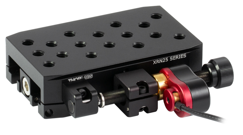
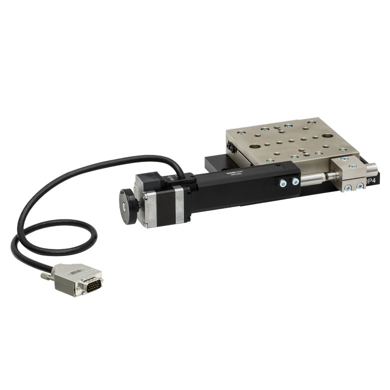
Compact Modular XRN25X 25 mm Stage |
Modular XR25X 25 mm Stage |
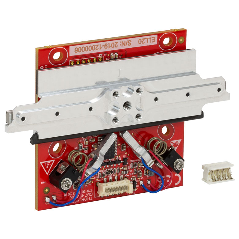
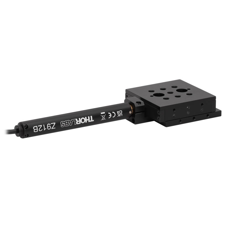
Elliptec® 28 mm Stage | Elliptec® 60 mm Stage | LPS710E 1.1 mm Vertical Stage |
| Click Photo to Enlarge |
 |
 |
 |
 |
 |
 |
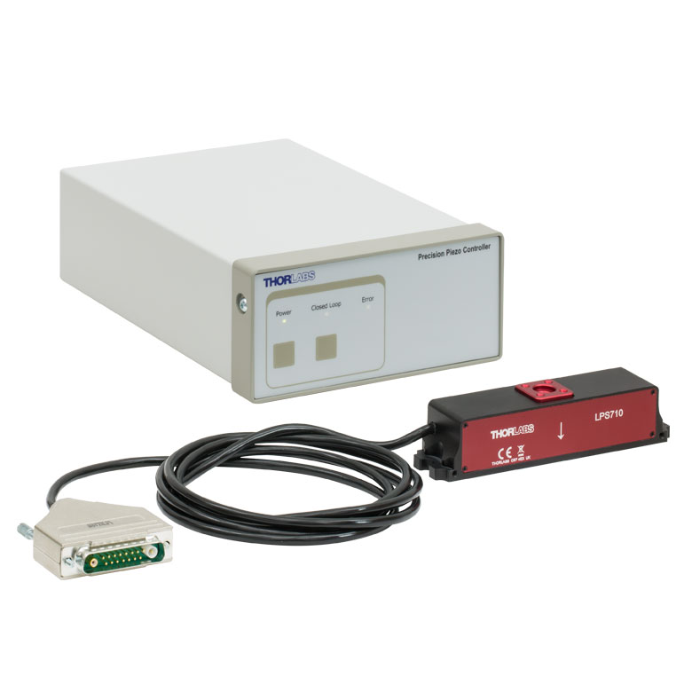 |
| Travel | 20 µm + 5 mm Manual | 25 µm + 1.5 mm Manual | 25 mm | 28 mm | 60.0 mm | 1.1 mm | |
| Maximum Velocity | - | ≤3.6 mm/mina | 180 mm/s | 90 mm/s | - | ||
| Drive Type | Piezo with Manual Actuator | Piezoelectric Inertia Drive | Resonant Piezoelectric Motor | Amplified Piezo | |||
| Possible Axis Configurations | X, XY, XYZ | X, XY, YZ, XZ, XYZ | X | Z | |||
| Mounting Surface Size | 75 mm x 75 mm | 30 mm x 30 mm | 85.0 mm x 50.7 mm | 110.0 mm x 75.7 mm | 15 mm x 15 mm | 21 mm x 21 mm | |
| Additional Details | |||||||
Stepper Motor Stages
These translation stages feature removable or integrated stepper motors and long travel ranges up to 300 mm. Many of these stages either have integrated multi-axis capability (PLSXY) or can be assembled into multi-axis configurations (PLSX, LNR Series, NRT Series, and LTS Series stages). The MLJ150 stage also offers high load capacity vertical translation.
| Stepper Motor Stages | |||||
|---|---|---|---|---|---|
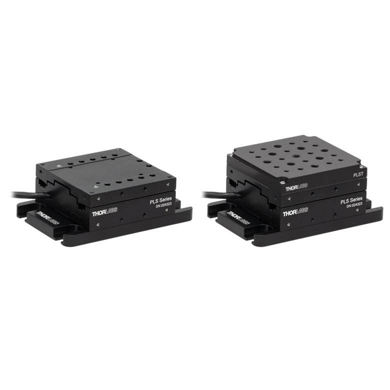
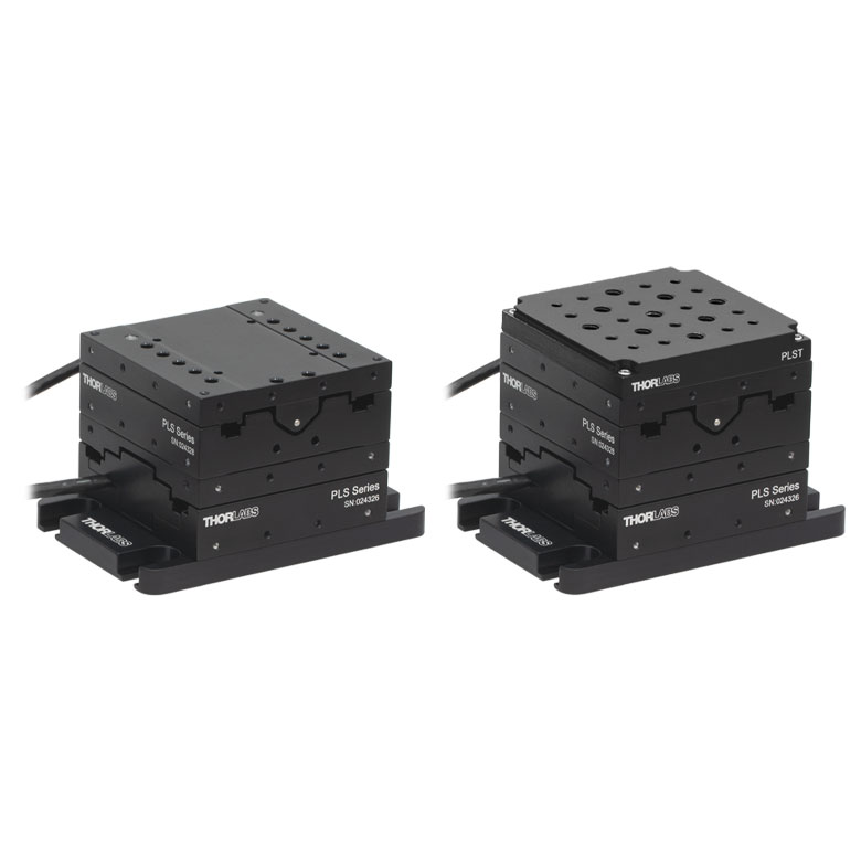
| Product Family | PLSX with and without PLST(/M) Top Plate 1" Stage |
PLSXY with and without PLST(/M) Top Plate 1" Stage |
LNR Series 25 mm Stage |
LNR Series 50 mm Stage |
|
| Click Photo to Enlarge |
 |
 |
 |
 |
|
| Travel | 1" | 25 mm | 50 mm | ||
| Maximum Velocity | 7.0 mm/s | 2.0 mm/s | 50 mm/s | ||
| Possible Axis Configurations |
X, XY | X, XY, XYZ | X, XY, XYZ | ||
| Mounting Surface Size |
3" x 3" | 60 mm x 60 mm | 100 mm x 100 mm | ||
| Additional Details | |||||
| Stepper Motor Stages | |||||||
|---|---|---|---|---|---|---|---|
| Product Family | NRT Series 100 mm Stage |
NRT Series 150 mm Stage |
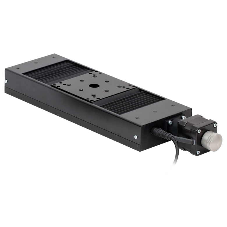
LTS Series 150 mm Stage |
LTS Series 300 mm Stage |
LTS Series 450 mm Stage |
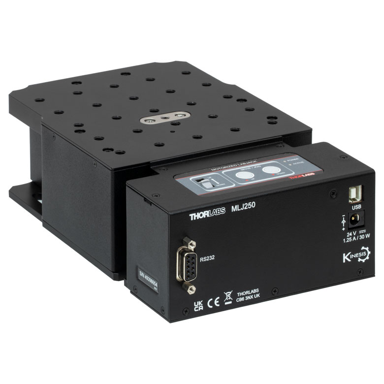
MLJ250 50 mm Vertical Stage |
|
| Click Photo to Enlarge |
 |
 |
 |
 |
 |
 |
|
| Travel | 100 mm | 150 mm | 150 mm | 300 mm | 400 mm | 50 mm | |
| Maximum Velocity | 30 mm/s | 50 mm/s | 3.0 mm/s | ||||
| Possible Axis Configurations |
X, XY, XYZ | X, XY, XYZ | X, XY | Z | |||
| Mounting Surface Size |
84 mm x 84 mm | 100 mm x 90 mm | 148 mm x 131 mm | ||||
| Additional Details | |||||||
DC Servo Motor Stages
Thorlabs offers linear translation stages with removable or integrated DC servo motors. These stages feature low profiles and many can be assembled in multi-axis configurations.
| DC Servo Motor Stages | ||||
|---|---|---|---|---|
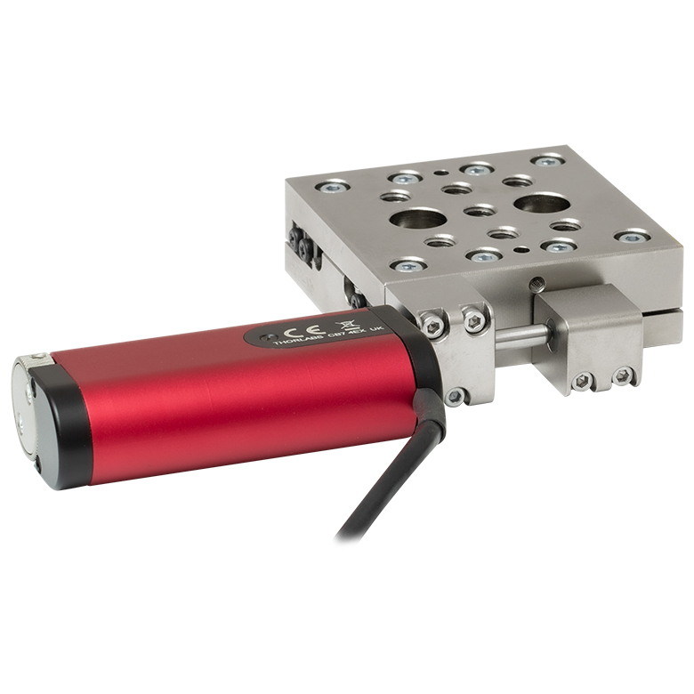
| Product Family | MT Series 12 mm Stages |
PT Series 25 mm Stages |
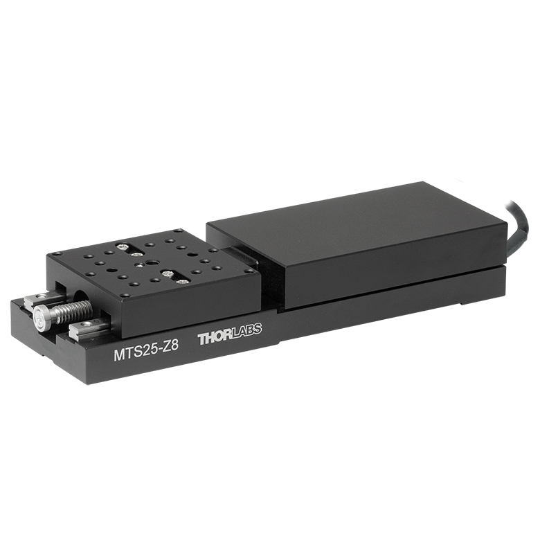
MTS Series 25 mm Stage |
MTS Series 50 mm Stage |
| Click Photo to Enlarge |
 |
 |
 |
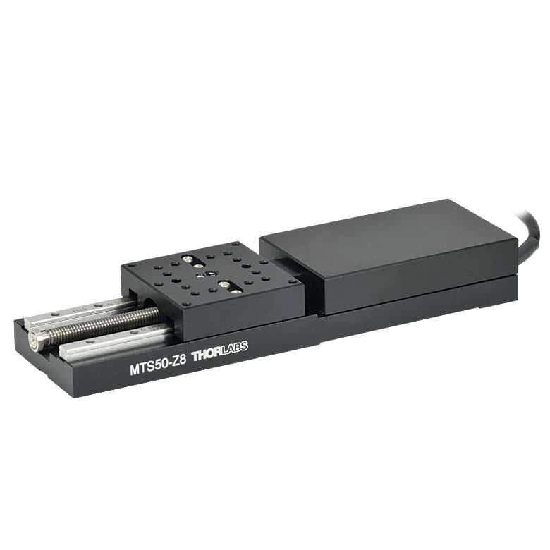 |
| Travel | 12 mm | 25 mm | 25 mm | 50 mm |
| Maximum Velocity | 2.6 mm/s | 2.4 mm/s | ||
| Possible Axis Configurations | X, XY, XYZ | X, XY, XYZ | ||
| Mounting Surface Size |
61 mm x 61 mm | 101.6 mm x 76.2 mm | 43 mm x 43 mm | |
| Additional Details | ||||
| DC Servo Motor Stages | ||||
|---|---|---|---|---|
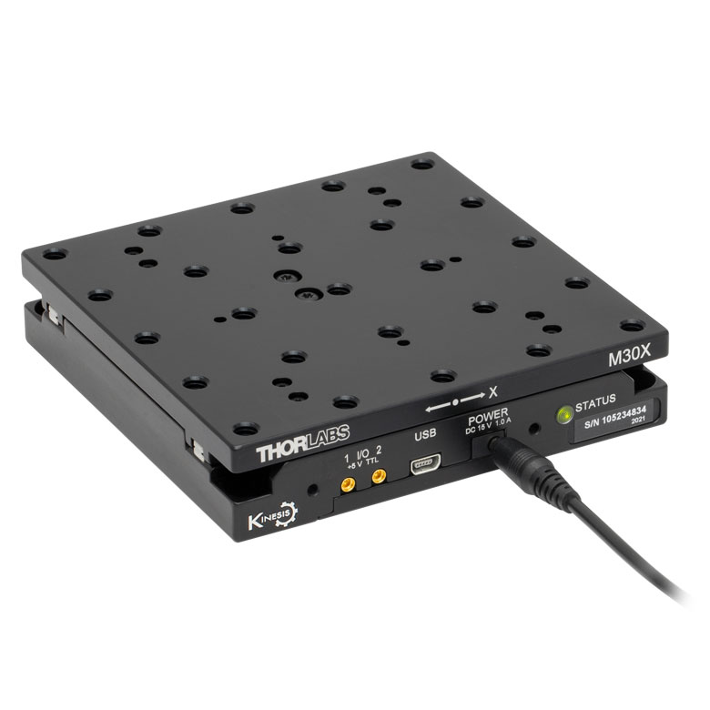
| Product Family | M30 Series 30 mm Stage |
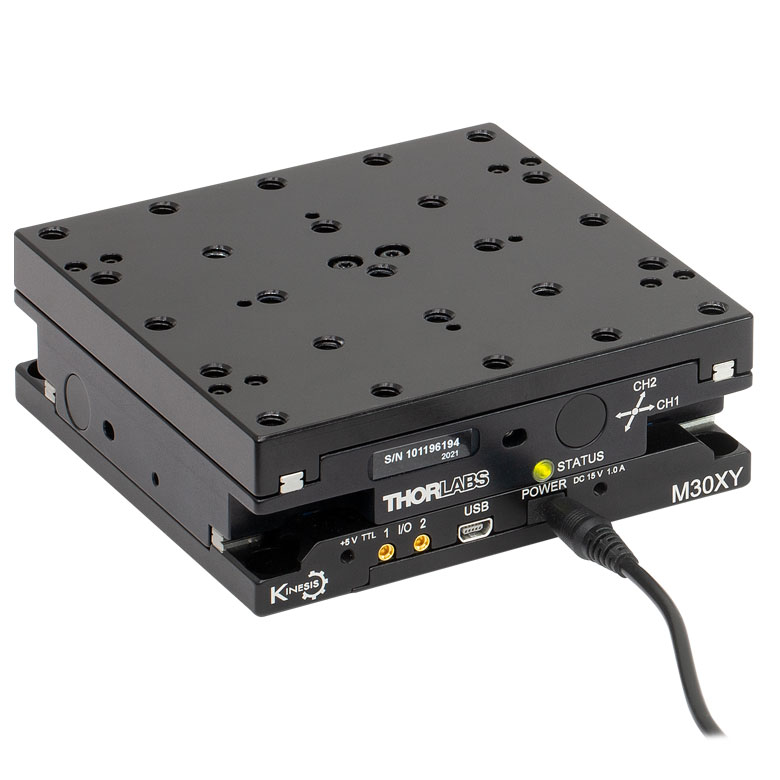
M30 Series 30 mm Monolithic XY Stage |
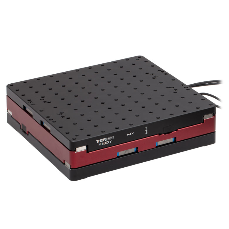
M150 Series 150 mm XY Stage |
KVS30 30 mm Vertical Stage |
| Click Photo to Enlarge |
 |
 |
 |
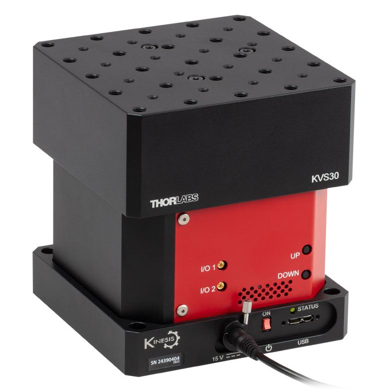 |
| Travel | 30 mm | 150 mm | 30 mm | |
| Maximum Velocity | 2.4 mm/s | X-Axis: 170 mm/s Y-Axis: 230 mm/s |
8.0 mm/s | |
| Possible Axis Configurations | X, Z | XY, XZ | XY | Z |
| Mounting Surface Size |
115 mm x 115 mm | 272.4 mm x 272.4 mm | 116.2 mm x 116.2 mm | |
| Additional Details | ||||
Direct Drive Stages
These low-profile stages feature integrated brushless DC servo motors for high speed translation with zero backlash. When no power is applied, the platforms of these stages have very little inertia and are virtually free running. Hence these stages may not be suitable for applications where the stage's platform needs to remain in a set position when the power is off. We do not recommend mounting these stages vertically.
| Direct Drive Stages | |||||
|---|---|---|---|---|---|
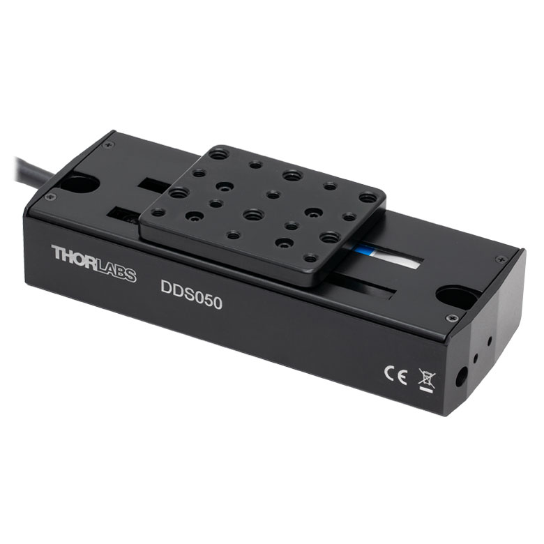
| Product Family | DDS Series 50 mm Stage |
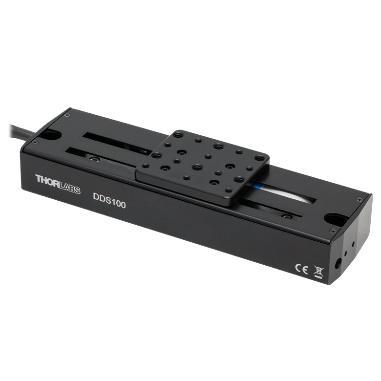
DDS Series 100 mm Stage |
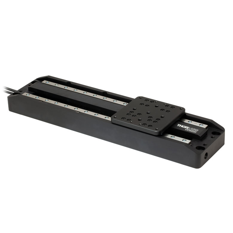
DDS Series 220 mm Stage |
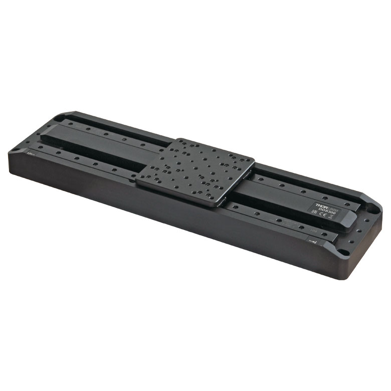
DDS Series 300 mm Stage |
DDS Series 600 mm Stage |
| Click Photo to Enlarge |
 |
 |
 |
 |
 |
| Travel | 50 mm | 100 mm | 220 mm | 300 mm | 600 mm |
| Maximum Velocity | 500 mm/s | 300 mm/s | 400 mm/s | 400 mm/s | |
| Possible Axis Configurations | X, XY | X, XY | X | X | |
| Mounting Surface Size | 60 mm x 52 mm | 88 mm x 88 mm | 120 mm x 120 mm | ||
| Additional Details | |||||

 Zoom
Zoom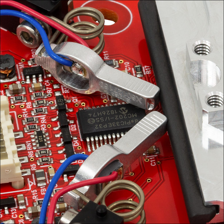
Click to Enlarge
Figure G1.2 The motors' aluminum tips contact the black plastic strip at the edge of the linear stage to translate the stage back and forth.
Click to Enlarge
Figure G1.1 ELL17K Linear Stage Bundle used to Position a Variable Slit
- Ideal for OEM Evaluation Testing
- Easily Integrate into a Setup
- Operate using Manual and/or Computer Control
- Included Power Supply is Required for Powering the Stage
The Linear Stage Bundle is a complete package that includes a linear stage and an interface board, which facilitate quick integration into laboratory setups and other experimental applications. It also provides a convenient means to evaluate incorporating this technology into OEM applications.
A mounting bracket included with the bundle fastens to the underside of the linear stage's PCB with four included screws. Two slots in the bracket align with the Ø11.0 mm (Ø0.43") holes at either side of the PCB, so that 1/4"-20 (M6) cap screws can be inserted through the holes in the PCB to secure the linear stage board to optical tables and breadboards. The bracket adds 5.0 mm of thickness to the profile of the stage.
| Included in the ELL17K(/M) Bundle | |
|---|---|
| ELL17(/M) Linear Stage | 5 V Power Supply |
| 8-Conductor 28 AWG Ribbon Cable | |
| ELLC Interface Board | Micro-B to Type-A USB Cable |
| Mounting Bracket | PC-Based Software for Download |

 Zoom
ZoomThis linear stage is offered individually to meet the needs of applications whose designs require multiple networked Elliptec® resonant motor products, or applications that do not require the other components included in the bundle above.
The ELL17 Linear Stage has a 28 mm travel range and a mounting surface featuring a center 8-32 (M4) tapped hole and four surrounding 4-40 (M3) tapped holes. Components may be mounted directly to the stage, or the 4-40 (M3) tapped holes can be used to secure an adapter plate, such as MMP1(/M) or RB13P1(/M), as a mounting surface. Please contact us to discuss customizing the stage, or to arrange to purchase a mounting bracket with the stage.
The PCB of the linear stage incorporates a male 8-pin Picoflex® connector (header). Each ELL17 stage ships with the female 8-pin Picoflex® connector (receptacle) that mates with the connector (header) on the board.

 Zoom
Zoom| Specifications | ||
|---|---|---|
| DC Voltage Input to Controller | 4.5 to 5.5 V | |
| Typical Current Consumption Per Module |
Movement | 800 mA |
| Standby | 50 mA | |
| Operating Temperature Range | 15 to 40 °C | |
| Maximum Supported Ribbon Cable Length | 520 mm (20.5") | |
| Dimensions (Interface Board Only) | 66.0 mm x 32.0 mm x 12.5 mm (2.60" x 1.26" x 0.49") |
|
| Weight (Interface Board Only) | 10.8 g (0.022 lbs) | |
- Convert Any Single ELL Device into a Kit by Adding the Following:
- ELLC Interface Board
- USB Micro-B Cable
- Picoflex®1 Cable
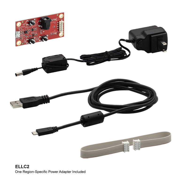
- Item # ELLC2 Only: 5 V Power Supply with Regional Adapter (US, UK, AU, or EU)

Click for Details
Figure 749A Region-Specific Adapters for the ELLC2 Power Adapter
Thorlabs' ELLCx Accessory Upgrade Packs are designed to provide the items necessary to convert any single ELL slider, stage, or mount into an ELL kit2. The interface board, included in the ELLC1 and ELLC2 kits (also sold separately as Item # ELLC) features three buttons to control the position of a connected ELL stage. The USB port enables direct connection to a PC via the USB Micro-B cable. A 0.25 m Picoflex® cable with 8 loaded circuits that connects the interface board to the ELL device is included, and a 5 V power supply with a regional adapter (US, UK, AU, or EU) is included with the ELLC2 kit.
1. Picoflex® is a registered trademark of Molex Incorporated.
2. Mounting brackets for the ELL17(/M), ELL18(/M), and ELL20(/M) can be ordered by contacting Tech Support.
| Table 749B Included in the ELLCx Accessory Upgrade Kits | ||||
|---|---|---|---|---|
| Item # | Interface Board | USB 2.0 Micro-B Cablea | Picoflex Cableb | 5 V Power Supplya,c |
| ELLC1 | - | |||
| ELLC2 | ||||

 Zoom
Zoom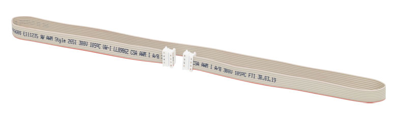
Click to Enlarge
Figure 813A ELLC4 Ribbon Cable
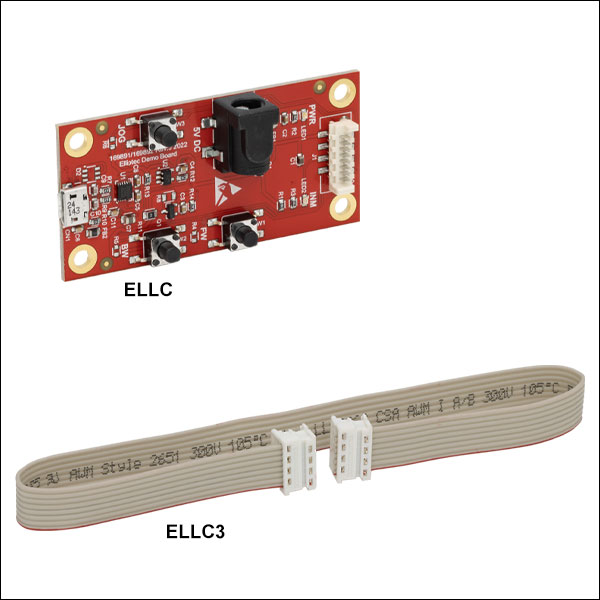
- ELLC Interface Board Provides Local and Remote (via USB) Control of Elliptec Devices
- Additional Picoflex®1 Cables:
- 250 mm (9.8") Long, Item # ELLC3
- 520 mm (20.5") Long, Item # ELLC4
The ELLC Interface Board features three buttons to control the position of a connected Elliptec device, please see the device-specific manuals for details. The interface board also provides a USB port for direct connection to a PC via a USB Micro-B cable, and a 5 VDC power socket for supplying power to the Elliptec device. An interface board is included as part of the Elliptec device bundles and as part of the ELLC1 and ELLC2 accessory upgrade kits.
Additional Picoflex® 8-conductor, 28 AWG cables for conencting Elliptec devices, interface boards, and bus distributors are also available. These ribbon cables are offered in lengths of 250 mm (9.8") or 520 mm (20.5"), Item #s ELLC3 and ELLC4, respectively, and are sold in packs of five.
1. Picoflex® is a registered trademark of Molex Incorporated.

 Zoom
Zoom| Specifications | ||
|---|---|---|
| Item # | ELLB | |
| Voltage Rating | 4.5 to 5.5 V | |
| Typical Current Consumption Per Module | Movement | 800 mA |
| Standby | 50 mA | |
| Maximum Board Current | 4.0 A | |
| Operating Temperature Range | 15 to 40 °C | |
| Ribbon Cable Length (4 Included) | 250 mm | |
| Maximum Supported Ribbon Cable Length |
500 mm | |
| Dimensions | 65.0 mm x 32.0 mm x 12.5 mm (2.56" x 1.26" x 0.49") |
|
| Weight | 11 g (0.02 lbs) | |
- Control and Power Up to Four Elliptec® Devices with One Bus
- Daisy Chain Bus Boards to Control Up to 16 Elliptec Devices
- Controlled Remotely Using Elliptec System Software (See Software Tab)
- Connect to PC Using USB Interface Board (Item # ELLC)
- Five Jumpers and Four 8-Conductor 28 AWG Ribbon Cables Included
- Compatible with Raspberry Pi® and Arduino® Boards
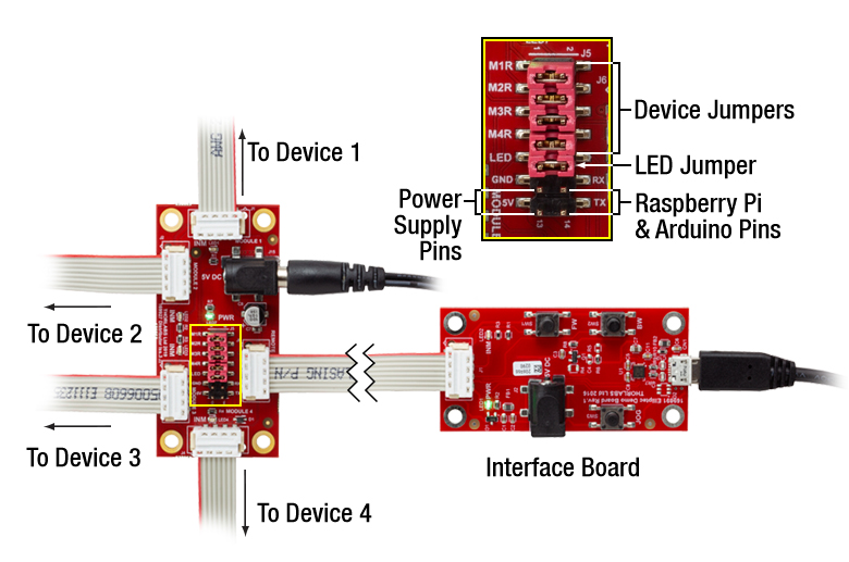
The ELLB Bus Distributor connects up to four Elliptec® devices. Connected devices can be controlled with or without the ELLC interface board, available as part of the above bundles or separately. When using the interface board, each connected device is controlled remotely by a PC running the Elliptec software package. The interface board connects to the bus's input port labeled REMOTE; once connected, the interface board's buttons are disabled. For control without using the interface board, see the Pin Diagrams tab for custom connections.
Multiple ELLB Bus Distributors can be daisy chained to control and power up to 16 Elliptec devices; simply connect one of the four MODULE outputs to the second board's REMOTE input. Indicator LEDs are provided to show which device is active. The communications protocol manual describes how to use the software to individually address each connected device. A link to download the software and accompanying documentation can be found in the Software tab.
The bus includes a Ø6.3 mm power connector that supports a 5 V supply with a maximum current of 4 A. As more devices are connected, simultaneous control of the units will require more current to be provided by the power supply. Please check the Specs tab for the amount of current drawn by each Ellitpec device and check that the power supply provides enough current to power two devices simultaneously.
Click to Enlarge
Figure 683A A single bus distributor can be used to control up to four Elliptec devices. The bus can be connected to a PC using the interface board provided with the bundles sold above. Note that the bus is then controlled by the Elliptec software and that the buttons on the interface board are disabled.
Fourteen control pins, detailed in Figure 683A, are included for additional functionality. Four pairs of pins are each shorted with a jumper that, when in place, enables the Elliptec software to receive feedback from connected Elliptec devices. The pair of pins labeled LED is shorted with a jumper that, when removed, will disable the indicator LEDs. The 5V and GND allow an optional, user-provided 5 V, 2 A power supply to be used in place of a source connected to the Ø6.3 mm power connector. The RX and TX pins can be used to control the bus with a Raspberry Pi® or Arduino® board, respectively, instead of the Elliptec interface board.
The board is mounted using the Ø3.5 mm through holes provided in each corner. Four 8-conductor, 28 AWG ribbon cables are included.
| Elliptec Resonant Motor Products | |||
|---|---|---|---|
|
|
|
|
| Multi-Position Sliders |
28 mm Linear Stage |
60 mm Linear Stage |
Rotation Stage |
|
|
|
|
| Ø1/2" Rotation Mount |
Ø1" Rotation Mount |
Ø2" Rotation Mount |
Motorized Irises |