 Products Home / Motorized Stages / Long Travel Linear Motorized Stages (>100 mm) / 100 mm Linear Translation Stage, Stepper Motor
100 mm Linear Translation Stage, Stepper Motor

- Stackable in XY, XZ, and XYZ Configurations
- Typical Calibrated On-Axis Accuracy of 2.0 µm
- Horizontal Load Capacity of 20 kg (44 lbs)
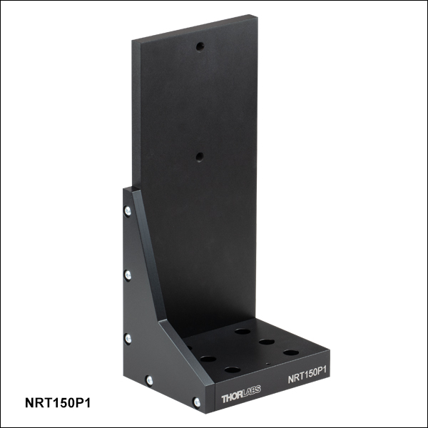
NRT150P1
Right-Angle Bracket
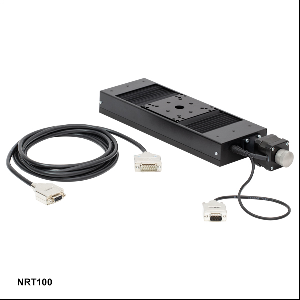
NRT100
100 mm Translation Stage
Application Idea
Two NRT100 Stages
in XZ Configuration,
Using an NRT150P1
Right-Angle Bracket


Please Wait
| Key Specificationsa | |
|---|---|
| Travel Range | 100 mm (3.9") |
| Velocity (Max)b | 30 mm/s |
| Minimum Achievable Incremental Movement | 0.1 µm |
| On-Axis Accuracyc | 2.0 µm (Typical) 5.0 µm (Max) |
| Bidirectional Repeatabilityd | 1 µm |
| Backlashe | <3 µm |
| Horizontal Load Capacity (Max) | 20 kg (44 lbs) |
| Vertical Load Capacity (Max) | 5 kg (11 lbs) |
| Actuator Type | Stepper Motor |
| Cable Length | 3.0 m (9.8 ft) |
| Recommended Controller | Benchtop Stepper Motor Controllers |
| Motorized Linear Translation Stages | |
|---|---|
| 100 mm | Stepper |
| DC Servo | |
| 150 mm | Stepper |
| Stepper with Integrated Controller | |
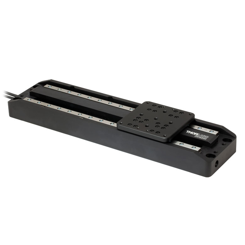
| 220 mm | DC Servo |
| 300 mm | Stepper with Integrated Controller |
| DC Servo | |
| 600 mm | DC Servo |
| Optical Delay Line Kits | |
| Other Translation Stages | |
Features
- 100 mm Travel Range
- Load Capacity
- Horizontal: 20 kg (44 lbs)
- Vertical: 5 kg (11 lbs)
- Maximum Velocity of 30 mm/s
- Bidirectional Repeatability of 1 µm
- XY, XZ, and XYZ Configurable
- 1/4"-20 (M6) Tapped Holes for Mounting Standard Optomechanics
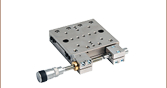
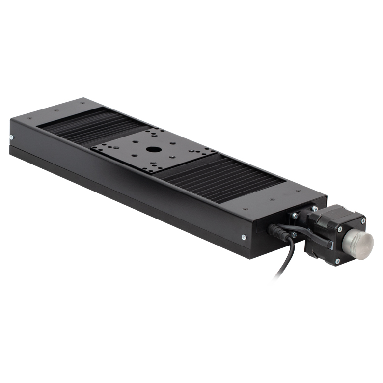
Thorlabs' NRT100(/M) Linear Positioning Stage is optimized for applications requiring high load capacity and high resolution, such as measurement and inspection. It provides 100 mm of linear travel for loads as great as 20 kg (44 lbs) when mounted horizontally and 5 kg (11 lbs) when mounted vertically. Each stage features a typical on-axis accuracy of 2.0 µm (5.0 µm Max) when the included calibration files are used with Thorlabs' Kinesis® or APT™ software. The lead screw, directly driven by a two-phase stepper motor with 409,600 microsteps per revolution, provides smooth translation with a theoretical positional resolution of less than 100 nm. Due to the stepper motor design, the platform position remains fixed when no power is supplied to the stage, unlike with DC servo motor translation stages.
The main platform is supported by four recirculating ball carrier bearings mounted to precisely aligned linear guide rails. The stepper motor, specifically designed for microstepping applications, allows smaller and smoother low-speed motion with significantly reduced vibrational noise than DC servo motors. The choice of a trapezoidal lead screw provides a number of benefits over the more common Acme-style thread, including improved durability, lower friction due to improved surface quality, and very little backdrive, eliminating the need for the braking mechanism required with ball screws.
Calibration Files
Each NRT100(/M) Linear Translation Stage is calibrated during manufacturing. Calibration enables the controller to correct for any mechanical errors present in the system. Mechanical components, such as the lead screw and linkages, can be machined only within a certain tolerance. These mechanical errors result in deviations of the actual position from the commanded position. However, the deviations are repeatable and can be compensated for using the Kinesis or APT™ software and included calibration files, which convert the position entered by the user into the required mechanical motion. The calibration files can be downloaded by clicking on the red Docs icon  )
)
The use of calibration files is optional. Without installing a calibration file, the on-axis accuracy of a stage will fall from 2.0 µm (typical) to 15.29 µm (typical). Calibration files do not affect the repeatability and resolution of the stages.
Stage Combinations
If an XY configuration is desired, any combination of NRT100 and NRT150 Linear Positioning Stages (the latter features a 150 mm travel range) can be mounted directly atop one another by using 1/4"-20 (M6) cap screws together with the provided counterbored holes and slots. These counterbores are accessed through the Ø0.59" (Ø15.0 mm) clearance hole in the moving carriage. XZ and XYZ configurations are possible using our NRT150P1(/M) Vertical Mounting Bracket, which orients either an NRT100 or NRT150 in the vertical plane.
Controller Options
One of Thorlabs' benchtop stepper motor controllers, available in one-, two-, or three-channel versions, is required to drive this 100 mm translation stage. These controllers are compatible with Kinesis and APT™ software, which supply out-of-the-box stage control from a PC and enables support for common programming interfaces like LabVIEW, LabWindows™, and ActiveX.
One PAA613 Motor Drive Cable is included with each of our NRT Series Translation Stages. Replacement cables are available below in case of loss or damage to the included cable.
| Item # | NRT100(/M) |
|---|---|
| Translation | |
| Travel Range | 100 mm (3.9") |
| Bidirectional Repeatabilitya | 1 µm |
| Backlashb | <3 µm |
| Maximum Velocityc | 30 mm/s |
| Velocity Stability | ±0.1 mm/s |
| Maximum Accelerationc | 30 mm/s2 |
| Minimum Achievable Incremental Movementd | 0.10 µm |
| Minimum Repeatable Incremental Movemente | 2 µm |
| Accuracy | |
| Calibrated Absolute On-Axis Accuracy | 2.0 µm (Typical) 5.0 µm (Max) |
| Maximum Percentage Accuracyf | 0.09% |
| Home Location Accuracy | ±0.6 µm |
| Pitch | <0.008° (140 µrad) |
| Yaw | <0.05° (873 µrad) |
| Load Capacity | |
| Horizontal Load Capacity | <12 kg (26 lbs) (Recommended) 20 kg (44 lbs) (Max) |
| Vertical Load Capacity | <4 kg (9 lbs) (Recommended) 5 kg (11 lbs) (Max) |
| General | |
| Weight | 2.2 kg (4.9 lbs) |
| Dimensions | 362.7 mm x 100.0 mm x 43.5 mm (14.28" x 3.94" x 1.71") |
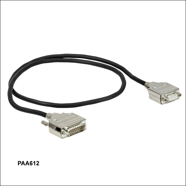
PAA612 and PAA613 Stepper Motor Cables
DA15-Pin Male D-Type to DE15-Pin Female D-Type
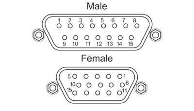
| DA15 Male Pin | DE15 Female Pin | Description |
|---|---|---|
| 11 and 12 | 1 | Limit Switch Ground |
| 10 | 2 | Forward Limit Switch |
| 9 | 3 | Reverse Limit Switch |
| 7 | 4 | Motor Phase B -ve |
| 14 | 5 | Motor Phase B +ve |
| 8 | 6 | Motor Phase A -ve |
| 15 | 7 | Motor Phase A +ve |
| 6 | 9 | Not Connected |
| 5 | 13 | Limit Switch +5 V |
Motor Pin Out
D-Type Male
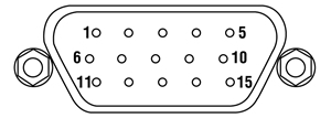
| Pin | Designation | Pin | Designation |
|---|---|---|---|
| 1 | Limit Switch Ground | 9 | Not Connected |
| 2 | Forward Limit Switch | 10 | Not Connected |
| 3 | Reverse Limit Switch | 11 | Not Connected |
| 4 | Motor Phase B -ve | 12 | Not Connected |
| 5 | Motor Phase B +ve | 13 | Limit Switch +5 V |
| 6 | Motor Phase A -ve | 14 | Not Connected |
| 7 | Motor Phase A +ve | 15 | Ground/Earth |
| 8 | Not Connected |
Thorlabs offers two platforms to drive our wide range of motion controllers: our Kinesis® software package or the legacy APT™ (Advanced Positioning Technology) software package. Either package can be used to control devices in the Kinesis family, which covers a wide range of motion controllers ranging from small, low-powered, single-channel drivers (such as the K-Cubes™ and T-Cubes™) to high-power, multi-channel, modular 19" rack nanopositioning systems (the APT Rack System).
The Kinesis Software features .NET controls which can be used by 3rd party developers working in the latest C#, Visual Basic, LabVIEW™, or any .NET compatible languages to create custom applications. Low-level DLL libraries are included for applications not expected to use the .NET framework. A Central Sequence Manager supports integration and synchronization of all Thorlabs motion control hardware.
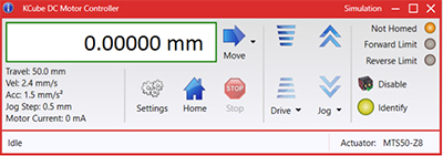
Kinesis GUI Screen
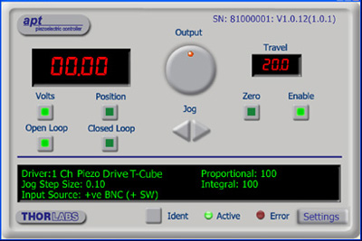
APT GUI Screen
Our legacy APT System Software platform offers ActiveX-based controls which can be used by 3rd party developers working on C#, Visual Basic, LabVIEW™, or any Active-X compatible languages to create custom applications and includes a simulator mode to assist in developing custom applications without requiring hardware.
By providing these common software platforms, Thorlabs has ensured that users can easily mix and match any of the Kinesis and APT controllers in a single application, while only having to learn a single set of software tools. In this way, it is perfectly feasible to combine any of the controllers from single-axis to multi-axis systems and control all from a single, PC-based unified software interface.
The software packages allow two methods of usage: graphical user interface (GUI) utilities for direct interaction with and control of the controllers 'out of the box', and a set of programming interfaces that allow custom-integrated positioning and alignment solutions to be easily programmed in the development language of choice.
A range of video tutorials is available to help explain our APT system software. These tutorials provide an overview of the software and the APT Config utility. Additionally, a tutorial video is available to explain how to select simulator mode within the software, which allows the user to experiment with the software without a controller connected. Please select the APT Tutorials tab above to view these videos.
Software
Kinesis Version 1.14.47
The Kinesis Software Package, which includes a GUI for control of Thorlabs' Kinesis and APT™ system controllers.
Also Available:
- Communications Protocol
Software
APT Version 3.21.6
The APT Software Package, which includes a GUI for control of Thorlabs' APT™ and Kinesis system controllers.
Also Available:
- Communications Protocol
Thorlabs' Kinesis® software features new .NET controls which can be used by third-party developers working in the latest C#, Visual Basic, LabVIEW™, or any .NET compatible languages to create custom applications.
C#
This programming language is designed to allow multiple programming paradigms, or languages, to be used, thus allowing for complex problems to be solved in an easy or efficient manner. It encompasses typing, imperative, declarative, functional, generic, object-oriented, and component-oriented programming. By providing functionality with this common software platform, Thorlabs has ensured that users can easily mix and match any of the Kinesis controllers in a single application, while only having to learn a single set of software tools. In this way, it is perfectly feasible to combine any of the controllers from the low-powered, single-axis to the high-powered, multi-axis systems and control all from a single, PC-based unified software interface.
The Kinesis System Software allows two methods of usage: graphical user interface (GUI) utilities for direct interaction and control of the controllers 'out of the box', and a set of programming interfaces that allow custom-integrated positioning and alignment solutions to be easily programmed in the development language of choice.
For a collection of example projects that can be compiled and run to demonstrate the different ways in which developers can build on the Kinesis motion control libraries, click on the links below. Please note that a separate integrated development environment (IDE) (e.g., Microsoft Visual Studio) will be required to execute the Quick Start examples. The C# example projects can be executed using the included .NET controls in the Kinesis software package (see the Kinesis Software tab for details).
 |
Click Here for the Kinesis with C# Quick Start Guide Click Here for C# Example Projects Click Here for Quick Start Device Control Examples |
|
LabVIEW
LabVIEW can be used to communicate with any Kinesis- or APT-based controller via .NET controls. In LabVIEW, you build a user interface, known as a front panel, with a set of tools and objects and then add code using graphical representations of functions to control the front panel objects. The LabVIEW tutorial, provided below, provides some information on using the .NET controls to create control GUIs for Kinesis- and APT-driven devices within LabVIEW. It includes an overview with basic information about using controllers in LabVIEW and explains the setup procedure that needs to be completed before using a LabVIEW GUI to operate a device.
 |
Click Here to View the LabVIEW Guide Click Here to View the Kinesis with LabVIEW Overview Page |
|
The APT video tutorials available here fall into two main groups - one group covers using the supplied APT utilities and the second group covers programming the APT System using a selection of different programming environments.
Disclaimer: The videos below were originally produced in Adobe Flash. Following the discontinuation of Flash after 2020, these tutorials were re-recorded for future use. The Flash Player controls still appear in the bottom of each video, but they are not functional.
Every APT controller is supplied with the utilities APTUser and APTConfig. APTUser provides a quick and easy way of interacting with the APT control hardware using intuitive graphical control panels. APTConfig is an 'off-line' utility that allows various system wide settings to be made such as pre-selecting mechanical stage types and associating them with specific motion controllers.
APT User Utility
The first video below gives an overview of using the APTUser Utility. The OptoDriver single channel controller products can be operated via their front panel controls in the absence of a control PC. The stored settings relating to the operation of these front panel controls can be changed using the APTUser utility. The second video illustrates this process.
APT Config Utility
There are various APT system-wide settings that can be made using the APT Config utility, including setting up a simulated hardware configuration and associating mechanical stages with specific motor drive channels. The first video presents a brief overview of the APT Config application. More details on creating a simulated hardware configuration and making stage associations are present in the next two videos.
APT Programming
The APT Software System is implemented as a collection of ActiveX Controls. ActiveX Controls are language-independant software modules that provide both a graphical user interface and a programming interface. There is an ActiveX Control type for each type of hardware unit, e.g. a Motor ActiveX Control covers operation with any type of APT motor controller (DC or stepper). Many Windows software development environments and languages directly support ActiveX Controls, and, once such a Control is embedded into a custom application, all of the functionality it contains is immediately available to the application for automated operation. The videos below illustrate the basics of using the APT ActiveX Controls with LabVIEW, Visual Basic, and Visual C++. Note that many other languages support ActiveX including LabWindows CVI, C++ Builder, VB.NET, C#.NET, Office VBA, Matlab, HPVEE etc. Although these environments are not covered specifically by the tutorial videos, many of the ideas shown will still be relevant to using these other languages.
Visual Basic
Part 1 illustrates how to get an APT ActiveX Control running within Visual Basic, and Part 2 goes on to show how to program a custom positioning sequence.
LabVIEW
Full Active support is provided by LabVIEW and the series of tutorial videos below illustrate the basic building blocks in creating a custom APT motion control sequence. We start by showing how to call up the Thorlabs-supplied online help during software development. Part 2 illustrates how to create an APT ActiveX Control. ActiveX Controls provide both Methods (i.e. Functions) and Properties (i.e. Value Settings). Parts 3 and 4 show how to create and wire up both the methods and properties exposed by an ActiveX Control. Finally, in Part 5, we pull everything together and show a completed LabVIEW example program that demonstrates a custom move sequence.
Part 1: Accessing Online Help
Part 2: Creating an ActiveX Control
Part 3: Create an ActiveX Method
Part 4: Create an ActiveX Property
Part 5: How to Start an ActiveX Control
The following tutorial videos illustrate alternative ways of creating Method and Property nodes:
Create an ActiveX Method (Alternative)
Create an ActiveX Property (Alternative)
Visual C++
Part 1 illustrates how to get an APT ActiveX Control running within Visual C++, and Part 2 goes on to show how to program a custom positioning sequence.
MATLAB
For assistance when using MATLAB and ActiveX controls with the Thorlabs APT positioners, click here.
To further assist programmers, a guide to programming the APT software in LabVIEW is also available here.
| Posted Comments: | |
user
(posted 2023-09-06 16:18:51.547) Hello,
i wonder if this stage is compatible with the new KST201 K-Cube controller.
Thank you very much fguzman
(posted 2023-09-08 05:26:20.0) Thanks for your enquiry. The 100 mm Linear Translation Stage, Stepper Motor needs the BSC controller https://www.thorlabs.com/newgrouppage9.cfm?objectgroup_id=1704 If you have any other enquiries please contact Europe@thorlabs.com Andy Nave
(posted 2022-08-25 09:53:43.39) Hi,
I think there is a problem with the APT software as it seems it cannot initialise properly while a file is being read or written to.
I have a python script which is continuously reading a file and only when it is turned on the APT software cannot find the stage connected to the computer.
However, if I first start the APT software and then turn on the python script everything is fine.
Could you solve this issue?
Thanks DJayasuriya
(posted 2022-08-25 09:55:26.0) Thank you for your inquiry, This may depend on the file that your reading and the your script opens a connection to the device. We have got in touch with you directly to resolve the issue. Thomas Panier
(posted 2022-03-30 14:53:44.883) Hi, is it possible to control this stage with a K-Cube™ Stepper Motor Controller? Thanks. cwright
(posted 2022-04-01 05:26:11.0) Response from Charles at Thorlabs: Thank you for your query. The NRT100 requires the benchtop range of controllers due to the high current requirement of the stage and they cannot be used with the KST101 controllers. Xi Tang
(posted 2021-08-12 17:13:11.31) Dear Thorlabs,I prefer to know what's kind of your product' s operation temperatures range is -20℃ to 60℃ and 20mm to 200mm's travel range fulfill our requirements. If your company have such kinds of product, can you sent the specification of this product to my e-mail. DJayasuriya
(posted 2021-08-17 06:12:07.0) thank you for your inquiry. We will get in touch with you directly to discuss your application. user
(posted 2021-06-14 17:37:31.44) Dear Thorlabs,
Hello, I would like to control NRT100/M stage and BSC202 by Python.
So, could you please send me example codes?
Thanks!! cwright
(posted 2021-06-15 05:41:01.0) Response from Charles at Thorlabs: Hello and thank you for your query. While we do not officially support python we do have an example we can provide as a courtesy. There are a few ways you can use Python with our controllers. You would be able to use Kinesis’ .NET API via the clr module (if you're using IronPython) or Kinesis’s C API via the ctypes module(if you're using CPython). The DLLs required are located in the installation directory. Alternatively, as our devices use an FTDI chip to communicate with a host PC over USB, you can use serial commands via the pySerial module. The requisite commands and serial parameters can be found in our communications protocol - https://www.thorlabs.com/Software/Motion%20Control/APT_Communications_Protocol.pdf Andrew Allan
(posted 2020-11-18 06:30:22.127) Is the NRT100 supported through the ThorlabsAPTStage Micromanager driver? cwright
(posted 2020-11-19 09:16:38.0) Response from Charles at Thorlabs: Hello Andrew and thank you for your query. Unfortunately the NRT100 is not supported by Micromanager at this time. Please note that this is third party software so Thorlabs cannot add this support. akuznetsov
(posted 2018-07-03 20:13:29.4) The entire Thorlabs selection of motion controllers using APT and Kinesis software does not fit the constraints of a lab where automation equipment must be OS agnostic. For specific stations, and as a general practice, we obtain equipment such that we could automate it with Windows and macOS, RS-232 interface has been very helpful with this task. When testing DUT which are OS specific, the automated equipment must be controlled under the same OS as the DUT, otherwise it's not automated anymore. I've brought up this issue with Thorlabs for almost a year now and there's still no progress. rmiron
(posted 2018-07-11 06:20:04.0) Response from Radu at Thorlabs: Thank you for your feedback. It might not look like it, but the fact that customers such as yourself raise this issue repeatedly helps with pushing our development process in the right direction. This year we have in fact commenced work on translating our current .NET API into cross-platform .NET Core libraries. Unfortunately, because our resources are quite limited, progress is slow. Consequently, I don't expect the new API to be released until 2019. mohatiti341
(posted 2018-02-22 08:35:43.14) Is there any guide showing the control of benchtop stepper motor with LabVIEW ? rmiron
(posted 2018-02-26 11:57:29.0) Response from Radu at Thorlabs: There are two possible routes to controlling our stepper motor-driven devices via LabVIEW. One would be via the ActiveX controls supplied with our APT software. You can find a guide, along with plenty of examples, on this website under "Services"->"Downloads"->"Motion Controllers"->"APT with LabVIEW". In the installation path of APT you will also find a file named "APT Server Help" which is the documentation of the ActiveX-based API.
Alternatively, you can use the .NET controls supplied with our Kinesis software. Analogously to APT, under "Services"->"Downloads"->"Motion Controllers"->"Kinesis" you can find a guide for how to use those controls in LabVIEW. The documentation of this API can be found in the installation path of Kinesis under the name "Thorlabs.MotionControl.DotNet_API". Unfortunately, we lack example VIs for the .NET controls, but we are planning to add some in the coming year. user
(posted 2015-12-10 17:18:14.94) Is there a specification for the maximum torque which can be applied to the stage (for off-center loads which are not applied during motion)? bhallewell
(posted 2015-12-14 03:22:33.0) Response from Ben at Thorlabs: Thank you for your question here. We currently don't list a specification for off-axis torque loads for our motion control devices. I will contact you directly to discuss the performance of this stage within your application. jonathan
(posted 2013-03-20 15:24:29.213) The documentation under pin diagram uses a reverse numbering scheme than connectors have printed on them. Thorlabs defines the top RIGHT pin of a DB-15 HD cable to be pin 1. Even though the actual connector on the stage has a little "1" printed next to the pin that Thorlabs says in their documentation is pin "5".
Be VERY careful if you try to interface this with a third party motion controller, as you will end up connecting everything incorrectly. lmorgus
(posted 2013-03-21 08:30:46.77) A response from Laurie at Thorlabs to jonathan: Thank you for taking the time to point out an error on our website. You are correct that the pin diagram on our website was in error. We apologize for the frustration this likely caused. We have updated our documentation, both on the web under the "Pin Diagram" tab as well as the manual attached to our website to correct the error and prevent future confusion. jjurado
(posted 2011-08-29 11:02:00.0) Response from Javier at Thorlabs to sameera.atragji: Thank you for contacting us. We developed an interface, called the APT software, which is built on an ActiveX plaftorm, allowing for easy integration into the LabVIEW environment. We provide documentation in the form of video tutorials, a help file, sample vi's and an extensive pdf document to guide you in the process of controlling the stages through LabVIEW. The recommended controller for the NRT stepper motor stages is the BSC10x controller. Please visit the link below for links to the documentation mentioned above:
http://www.thorlabs.com/NewGroupPage9.cfm?ObjectGroup_ID=1704 (See Software and APT Tutorials tabs) sameera.atraqji
(posted 2011-08-29 05:38:08.0) Hello,
How can I use travel stage with labview.
Best regards,
Sameera |
Motorized Linear Translation Stages
Thorlabs' motorized linear translation stages are offered in a range of maximum travel distances, from a stage with 20 µm of piezo translation to our 600 mm direct drive stage. Many of these stages can be assembled in multi-axis configurations, providing XY or XYZ translation. For fiber coupling applications, please see our multi-axis stages, which offer finer adjustment than our standard motorized translation stages. In addition to motorized linear translation stages, we offer motorized rotation stages and goniometers. We also offer manual translation stages.
Piezo Stages
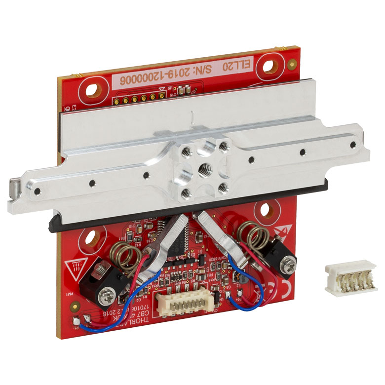
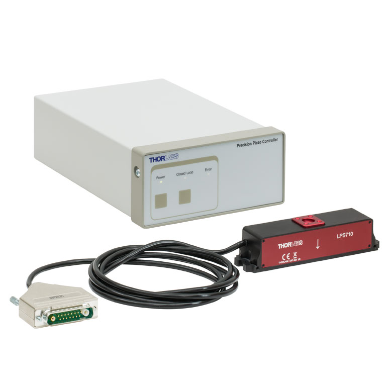
These stages incorporate piezoelectric elements in a variety of drive mechanisms. ORIC® stages incorporate piezo inertia drives that use "stick-slip" friction properties to obtain extended travel ranges. Our Nanoflex™ translation stages use standard piezo chips along with manual actuators. Elliptec® stages use resonant piezo motors to push and pull the moving platform through resonant elliptical motion. Our LPS710E z-axis stage features a mechanically amplified piezo design and includes a matched controller.
| Piezoelectric Stages | ||||
|---|---|---|---|---|
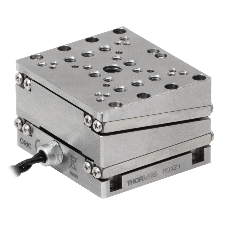
| Product Family | ORIC® PDXZ1 Closed-Loop 4.5 mm Vertical Stage |
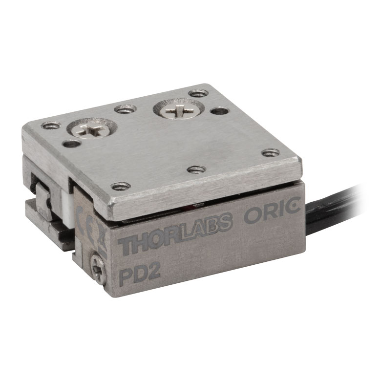
ORIC® PD2 Open-Loop 5 mm Stage |
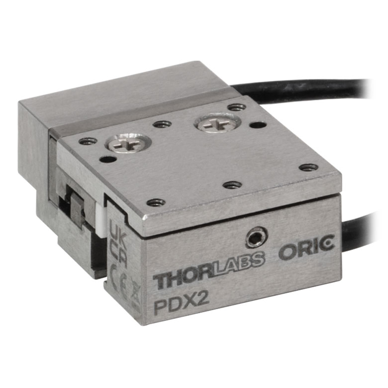
ORIC® PDX2 Closed-Loop 5 mm Stage |
|
| Click Photo to Enlarge |
 |
 |
 |
|
| Travel | 4.5 mm | 5 mm | ||
| Speed | 1 mm/s (Typ.)a | 10 mm/s (Typ. Max)b | 8 mm/s (Typ.)c | |
| Drive Type | Piezoelectric Inertia Drive | |||
| Possible Axis Configurations | Z | X, XY, XYZ | ||
| Mounting Surface Size |
45.0 mm x 42.0 mm | 13 mm x 13 mm | ||
| Additional Details | ||||
| Piezoelectric Stages | |||||
|---|---|---|---|---|---|
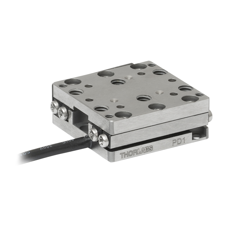
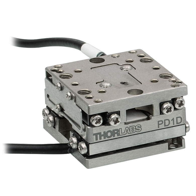
| Product Family | ORIC® PD1 Open-Loop 20 mm Stage |
ORIC® PD1D Open-Loop 20 mm Monolithic XY Stage |
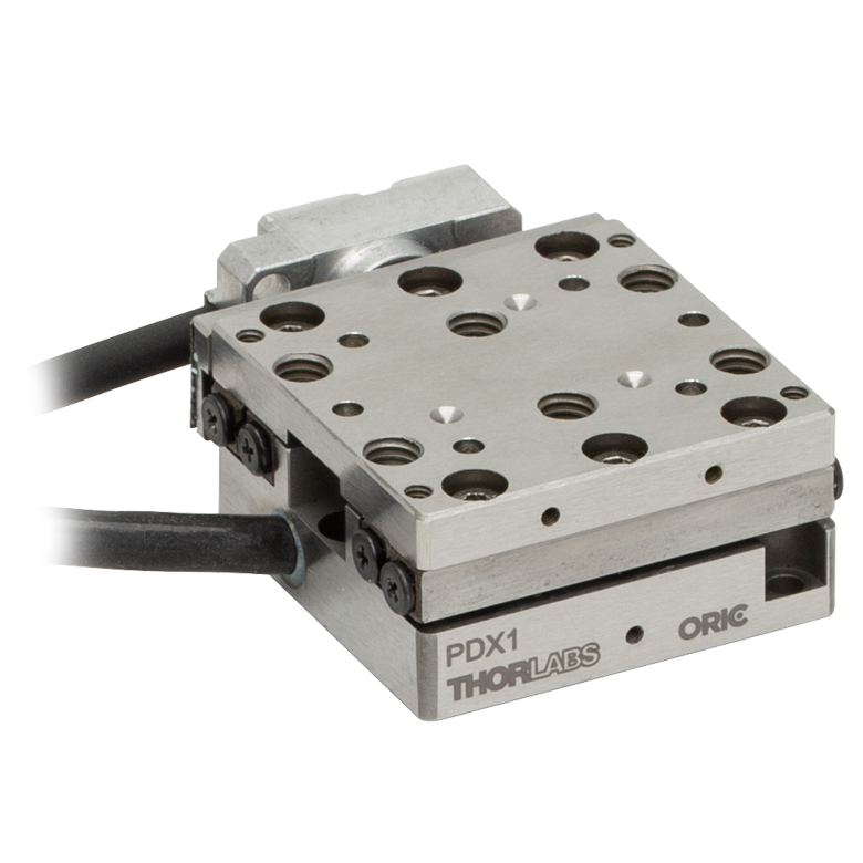
ORIC® PDX1 Closed-Loop 20 mm Stage |
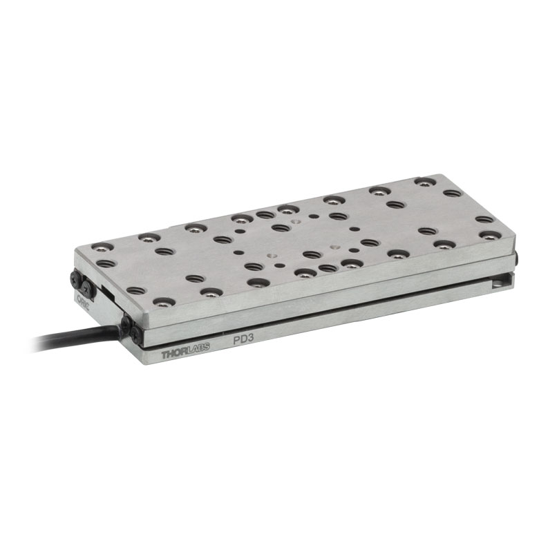
ORIC® PD3 Open-Loop 50 mm Stage |
|
| Click Photo to Enlarge |
 |
 |
 |
 |
|
| Travel | 20 mm | 50 mm | |||
| Speed | 3 mm/s (Typ. Max)a | 20 mm/s (Typ. Max)b | 10 mm/sc | ||
| Drive Type | Piezoelectric Inertia Drive | ||||
| Possible Axis Configurations | X, XY, XYZ | XY, XYZ | X, XY, XYZ | X, XY, XYZ | |
| Mounting Surface Size |
30 mm x 30 mm | 80 mm x 30 mm | |||
| Additional Details | |||||
| Piezoelectric Stages | ||||||
|---|---|---|---|---|---|---|
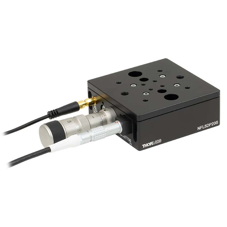
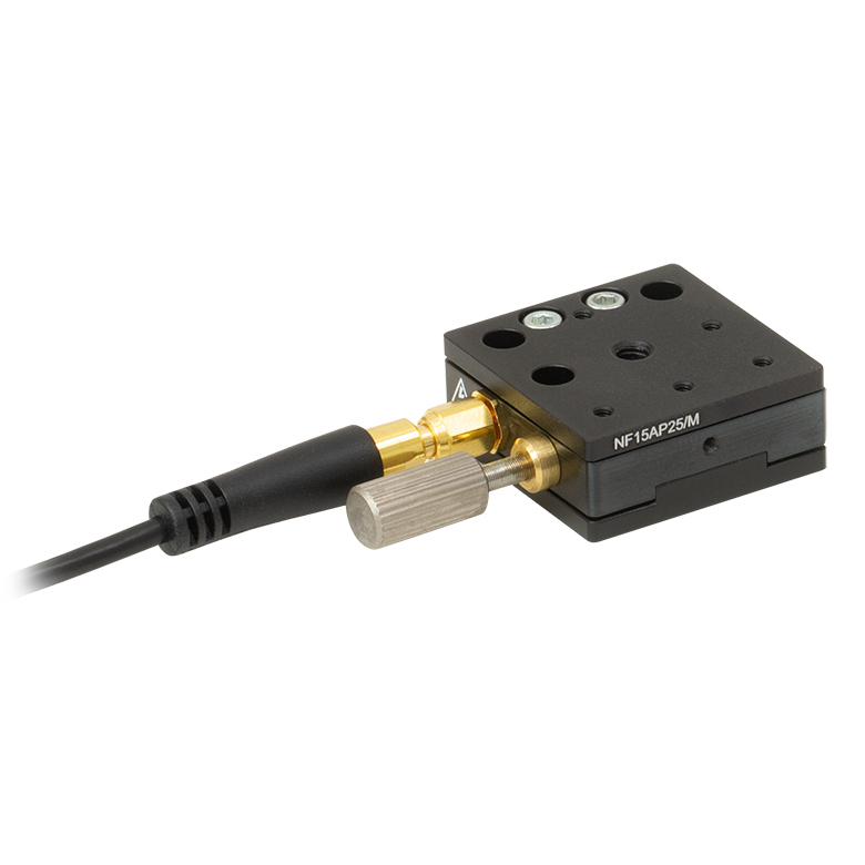
| Product Family | Nanoflex™ 20 µm Stage with 5 mm Actuator |
Nanoflex™ 25 µm Stage with 1.5 mm Actuator |
Elliptec® 28 mm Stage | Elliptec® 60 mm Stage | LPS710E 1.1 mm Vertical Stage | |
| Click Photo to Enlarge |
 |
 |
 |
 |
 |
|
| Travel | 20 µm + 5 mm Manual | 25 µm + 1.5 mm Manual | 28 mm | 60.0 mm | 1.1 mm | |
| Maximum Velocity | - | 180 mm/s | 90 mm/s | - | ||
| Drive Type | Piezo with Manual Actuator | Resonant Piezoelectric Motor | Amplified Piezo | |||
| Possible Axis Configurations | X, XY, XYZ | X | Z | |||
| Mounting Surface Size | 75 mm x 75 mm | 30 mm x 30 mm | 15 mm x 15 mm | 21 mm x 21 mm | ||
| Additional Details | ||||||
Stepper Motor Stages
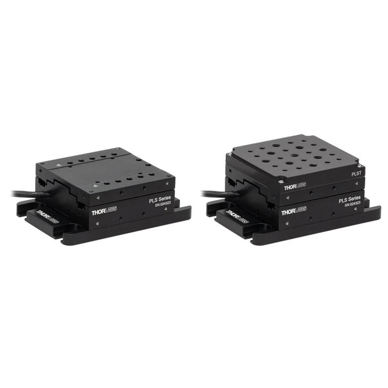
These translation stages feature removable or integrated stepper motors and long travel ranges up to 300 mm. Many of these stages either have integrated multi-axis capability (PLSXY) or can be assembled into multi-axis configurations (PLSX, LNR Series, NRT Series, and LTS Series stages). The MLJ150 stage also offers high load capacity vertical translation.
| Stepper Motor Stages | |||||
|---|---|---|---|---|---|
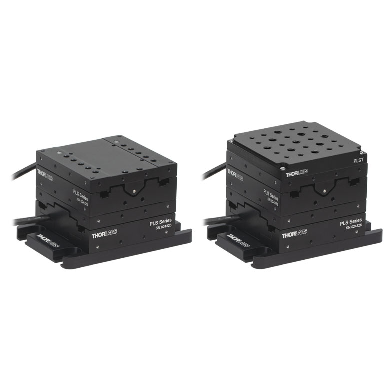
| Product Family | PLSX with and without PLST(/M) Top Plate 1" Stage |
PLSXY with and without PLST(/M) Top Plate 1" Stage |
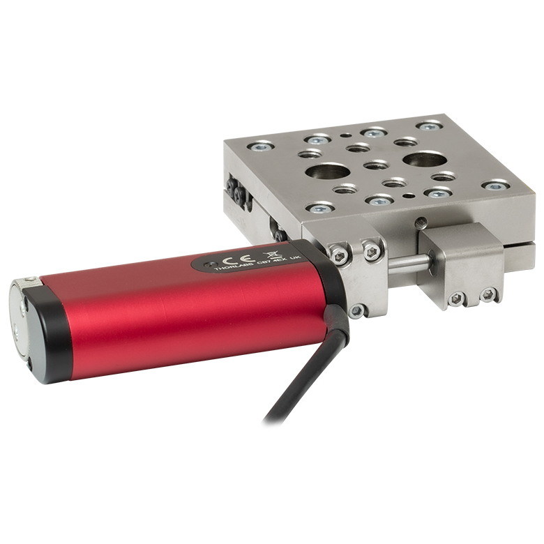
LNR Series 25 mm Stage |
LNR Series 50 mm Stage |
|
| Click Photo to Enlarge |
 |
 |
 |
 |
|
| Travel | 1" | 25 mm | 50 mm | ||
| Maximum Velocity | 7.0 mm/s | 2.0 mm/s | 50 mm/s | ||
| Possible Axis Configurations |
X, XY | X, XY, XYZ | X, XY, XYZ | ||
| Mounting Surface Size |
3" x 3" | 60 mm x 60 mm | 100 mm x 100 mm | ||
| Additional Details | |||||
| Stepper Motor Stages | ||||||
|---|---|---|---|---|---|---|
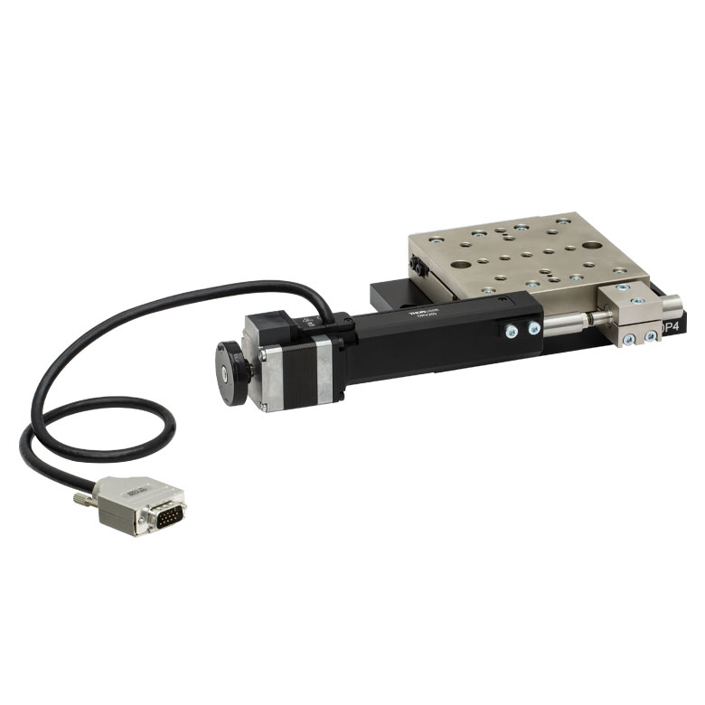
| Product Family | NRT Series 100 mm Stage |
NRT Series 150 mm Stage |
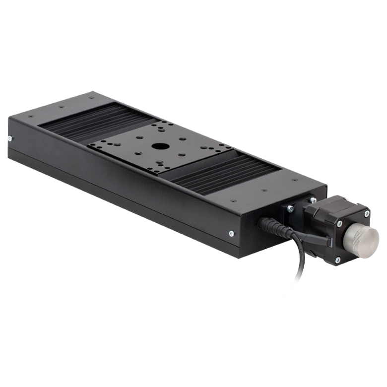
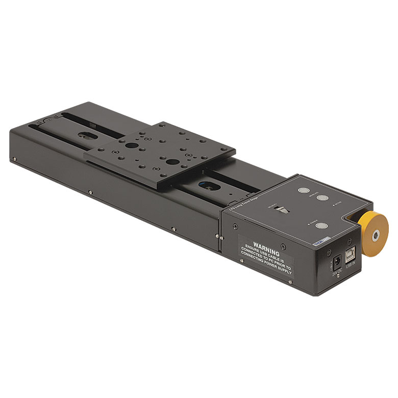
LTS Series 150 mm Stage |
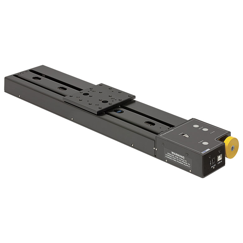
LTS Series 300 mm Stage |
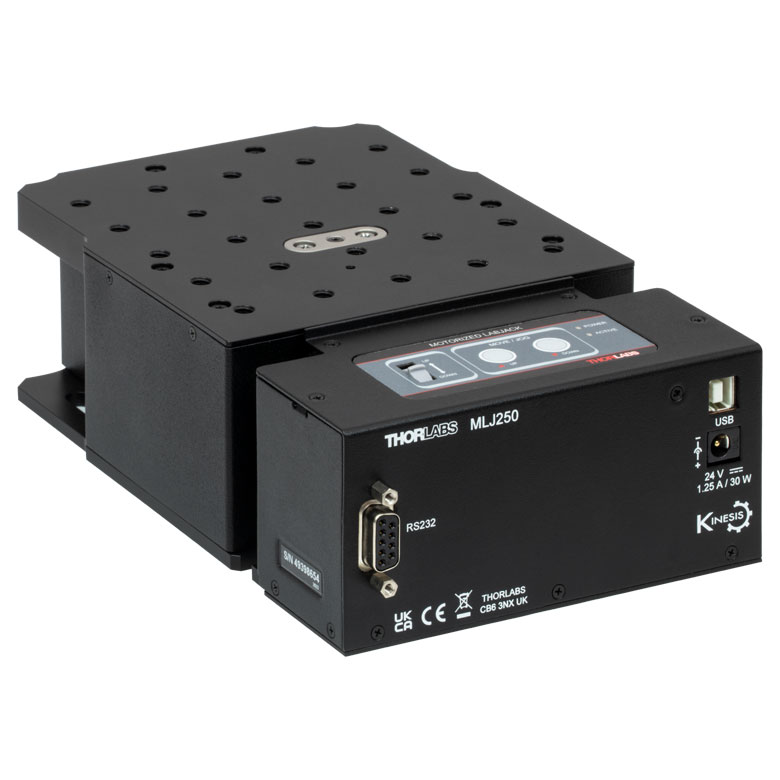
MLJ250 50 mm Vertical Stage |
|
| Click Photo to Enlarge |
 |
 |
 |
 |
 |
|
| Travel | 100 mm | 150 mm | 150 mm | 300 mm | 50 mm | |
| Maximum Velocity | 30 mm/s | 50 mm/s | 3.0 mm/s | |||
| Possible Axis Configurations |
X, XY, XYZ | X, XY, XYZ | Z | |||
| Mounting Surface Size |
84 mm x 84 mm | 100 mm x 90 mm | 148 mm x 131 mm | |||
| Additional Details | ||||||
DC Servo Motor Stages
Thorlabs offers linear translation stages with removable or integrated DC servo motors. These stages feature low profiles and many can be assembled in multi-axis configurations.
| DC Servo Motor Stages | ||||
|---|---|---|---|---|
| Product Family | MT Series 12 mm Stages |
PT Series 25 mm Stages |
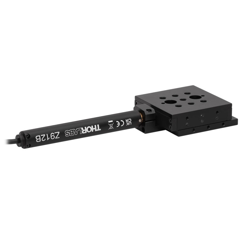
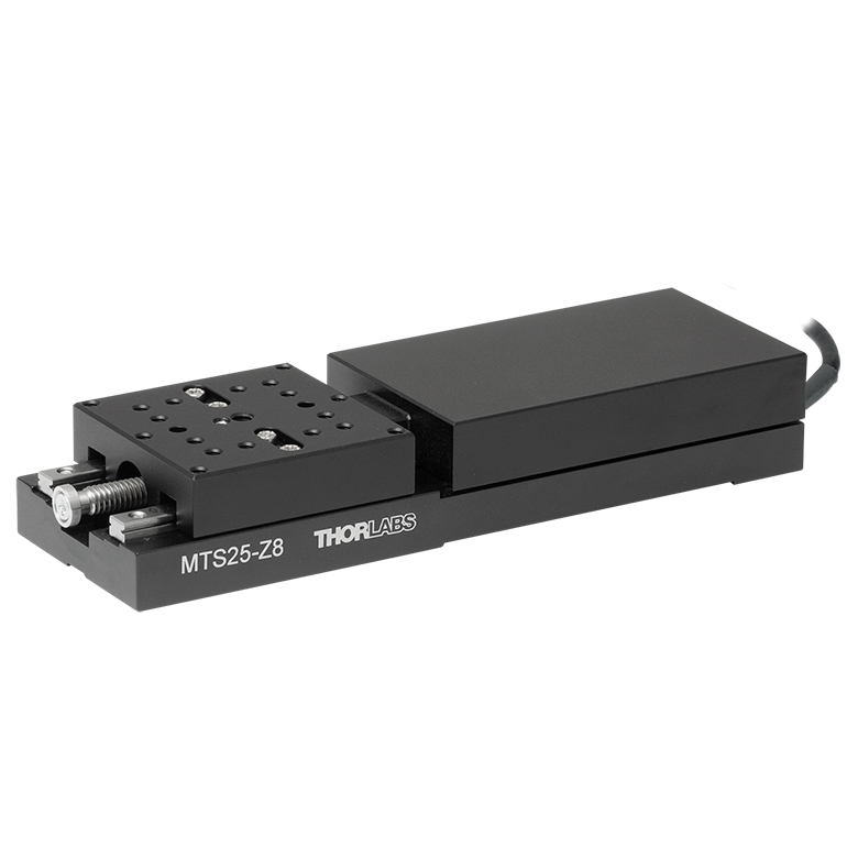
MTS Series 25 mm Stage |
MTS Series 50 mm Stage |
| Click Photo to Enlarge |
 |
 |
 |
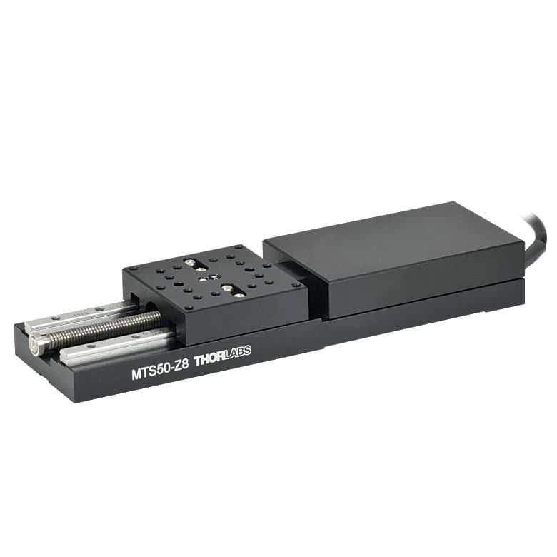 |
| Travel | 12 mm | 25 mm | 25 mm | 50 mm |
| Maximum Velocity | 2.6 mm/s | 2.4 mm/s | ||
| Possible Axis Configurations | X, XY, XYZ | X, XY, XYZ | ||
| Mounting Surface Size |
61 mm x 61 mm | 101.6 mm x 76.2 mm | 43 mm x 43 mm | |
| Additional Details | ||||
| DC Servo Motor Stages | ||||
|---|---|---|---|---|
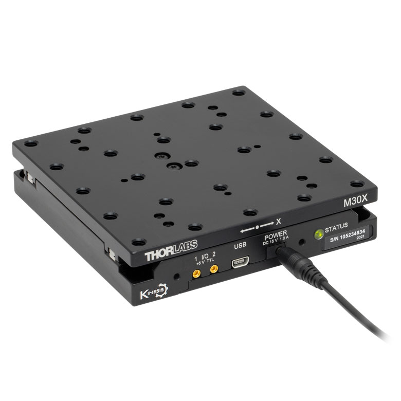
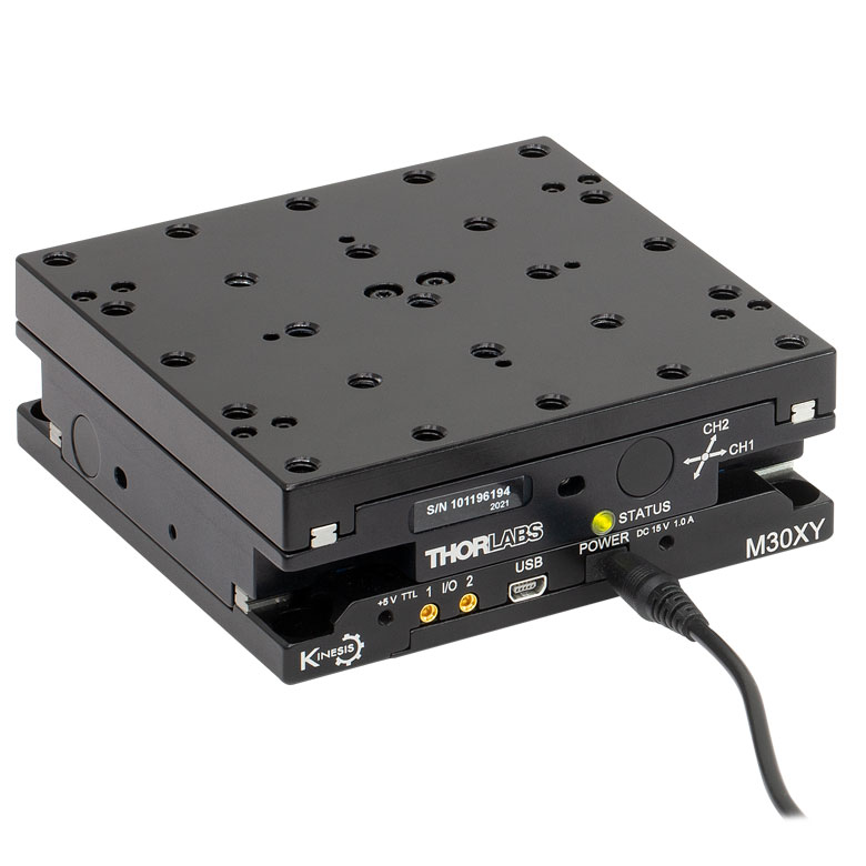
| Product Family | M30 Series 30 mm Stage |
M30 Series 30 mm Monolithic XY Stage |
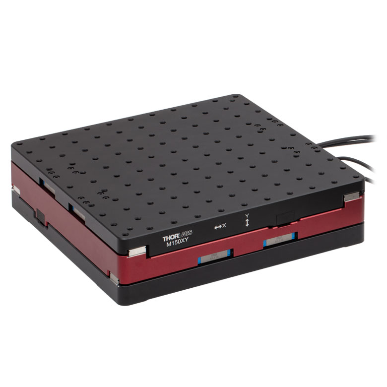
M150 Series 150 mm XY Stage |
KVS30 30 mm Vertical Stage |
| Click Photo to Enlarge |
 |
 |
 |
 |
| Travel | 30 mm | 150 mm | 30 mm | |
| Maximum Velocity | 2.4 mm/s | X-Axis: 170 mm/s Y-Axis: 230 mm/s |
8.0 mm/s | |
| Possible Axis Configurations | X, Z | XY, XZ | XY | Z |
| Mounting Surface Size |
115 mm x 115 mm | 272.4 mm x 272.4 mm | 116.2 mm x 116.2 mm | |
| Additional Details | ||||
Direct Drive Stages
These low-profile stages feature integrated brushless DC servo motors for high speed translation with zero backlash. When no power is applied, the platforms of these stages have very little inertia and are virtually free running. Hence these stages may not be suitable for applications where the stage's platform needs to remain in a set position when the power is off. We do not recommend mounting these stages vertically.
| Direct Drive Stages | |||||
|---|---|---|---|---|---|
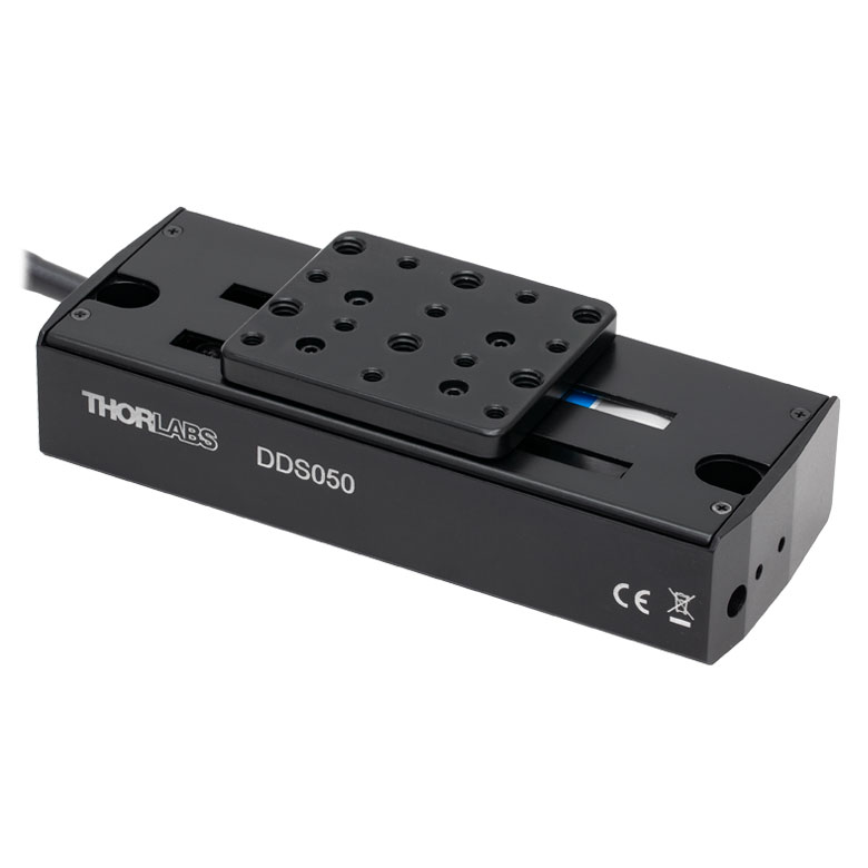
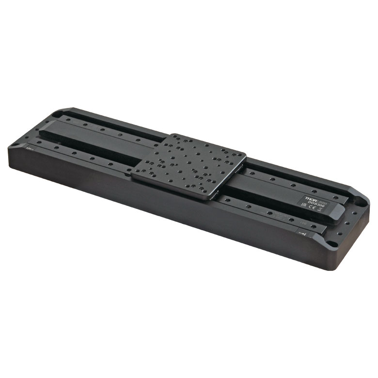
| Product Family | DDS Series 50 mm Stage |
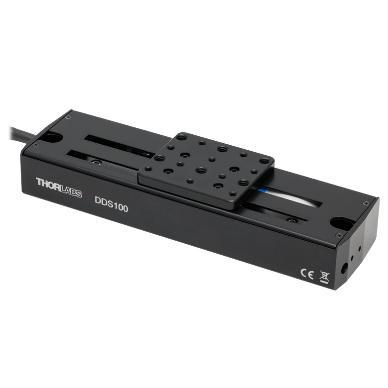
DDS Series 100 mm Stage |
DDS Series 220 mm Stage |
DDS Series 300 mm Stage |
DDS Series 600 mm Stage |
| Click Photo to Enlarge |
 |
 |
 |
 |
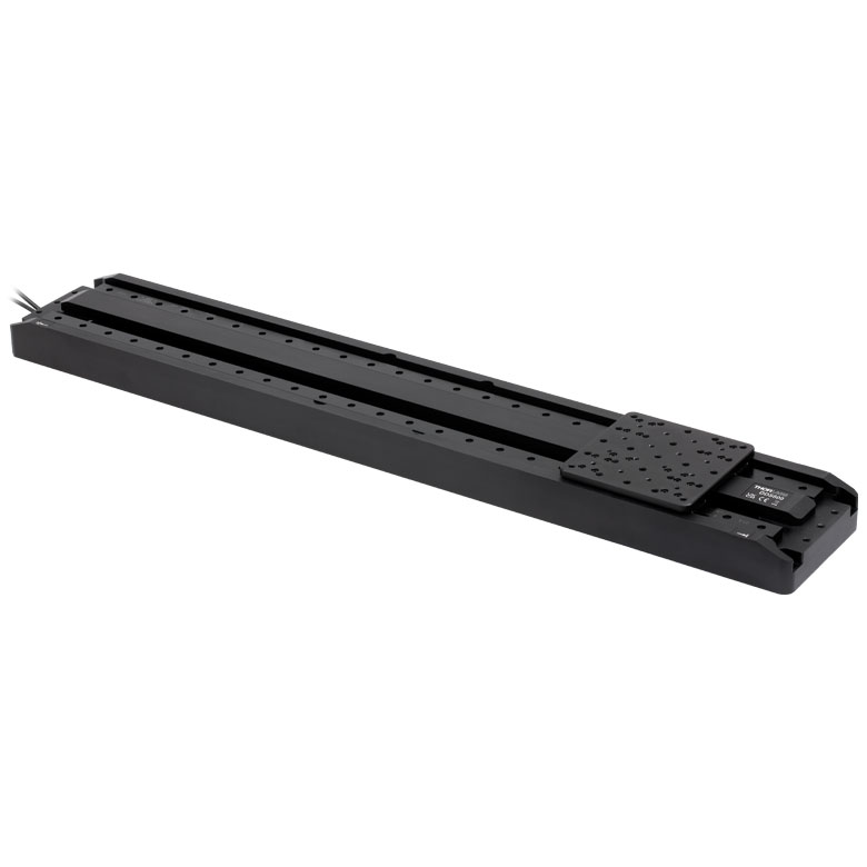 |
| Travel | 50 mm | 100 mm | 220 mm | 300 mm | 600 mm |
| Maximum Velocity | 500 mm/s | 300 mm/s | 400 mm/s | 400 mm/s | |
| Possible Axis Configurations | X, XY | X, XY | X | X | |
| Mounting Surface Size | 60 mm x 52 mm | 88 mm x 88 mm | 120 mm x 120 mm | ||
| Additional Details | |||||

 Zoom
Zoom
Thorlabs' NRT100(/M) stage provides 100 mm of travel with an integrated stepper motor. Optomechanics can be directly mounted to the moving platform using eight 1/4"-20 (M6) tapped holes, which are spaced 1.0" (25.0 mm) apart.

 Zoom
ZoomClick to Enlarge
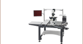
XZ Assembly Constructed Using the NRT150P1 Right-Angle Bracket and Two NRT100 Translation Stages
Click to Enlarge
NRT100 Stage Mounted Vertically on an NRT150P1 Bracket Attached Directly to an Optical Table
- For Constructing XZ and XYZ Stage Assemblies
- Attaches Directly to an Optical Table for Applications Requiring One Axis of Vertical Translation
The NRT150P1(/M) is an anodized aluminum right-angle bracket that orients an NRT100(/M) or NRT150(/M) translation stage in the vertical axis. This allows for the construction of XZ and XYZ translation stage arrangements (XZ option shown to the far right). Alternatively, the NRT150P1 can be directly attached to an optical table for applications that require one axis of vertical translation (shown to the right).
The base of the NRT150P1(/M) contains six counterbored holes for 1/4"-20 (M6) cap screws, while its side has two 1/4"-20 (M6) tapped holes. The two side taps are designed to accept the vertically mounted stage.

 Zoom
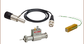
Zoom- Replacement Motor Drive Cables
- Available Lengths: 1 m (3.3') and 3 m (9.9')
One PAA613 Motor Drive Cable is included with each of our NRT Series Translation Stages. Replacement cables are available here in case of loss or damage to the included cable.
These cables are also compatible with our stepper motor actuators. The male end connects to the controller and the female end connects to the motor.