 Products Home / Motorized Stages / Motorized Linear Stages / Motorized 25 mm or 1" Linear Translation Stages / 25 mm (0.98") Stepper Motor Translation Stage, Crossed Roller Bearings
25 mm (0.98") Stepper Motor Translation Stage, Crossed Roller Bearings
- All-Steel Stage with 25 mm (0.98") of Travel
- Stepper Motor Actuator for Precise Motion and High Load Capacity
- TravelMax Stage with Crossed Roller Bearings
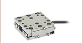
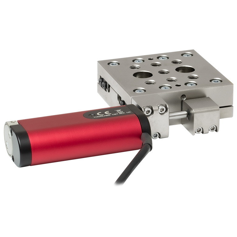
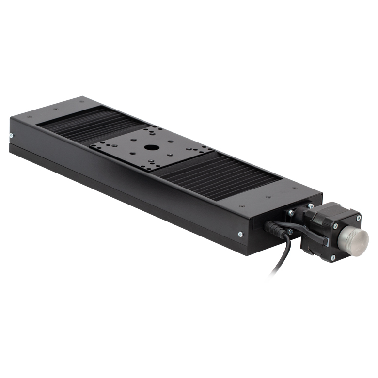
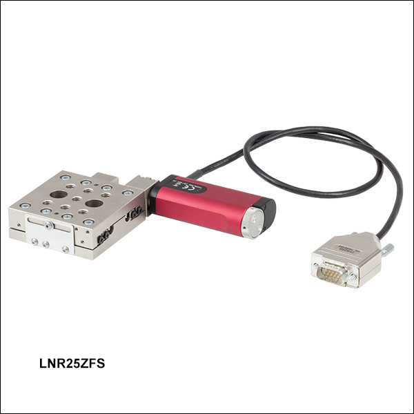
LNR25ZFS
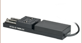
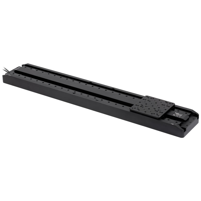
25 mm (0.98") Stepper Motor Translation Stage
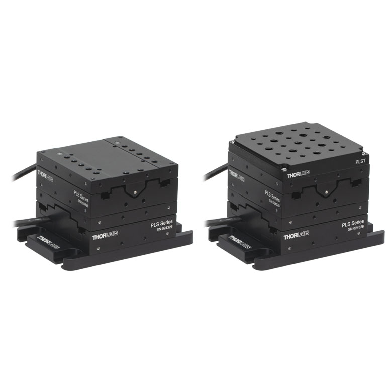
LNR25P2
Angle Bracket
Two LNR25ZFS Stages Mounted in an XY Configuration on an LNR25P1 Base Plate


Please Wait
| LNR25ZFS(/M) Specificationsa | ||
|---|---|---|
| Travel | 25 mm (0.98") | |
| Horizontal Load Capacityb | 5 kg (11 lbs) | |
| Vertical Load Capacity | 0.5 kg (1.1 lbs) | |
| Runout Over Full Range | ±1.5 µm | |
| Max Velocityc | 2.0 mm/s | |
| Max Accelerationc | 1.0 mm/s2 | |
| Calculated Minimum Incremental Movement |
0.46 nm | |
| Absolute On-Axis Accuracy | 15 µm | |
| Bidirectional Repeatability | 3.0 µm | |
| Home Switch Accuracy | <5.0 µm | |
| Bearings | Crossed Roller | |
| Body Construction | All Steel | |
| Weight (Including Actuator) | 0.73 kg (1.61 lbs) | |
Compatible
Controller:
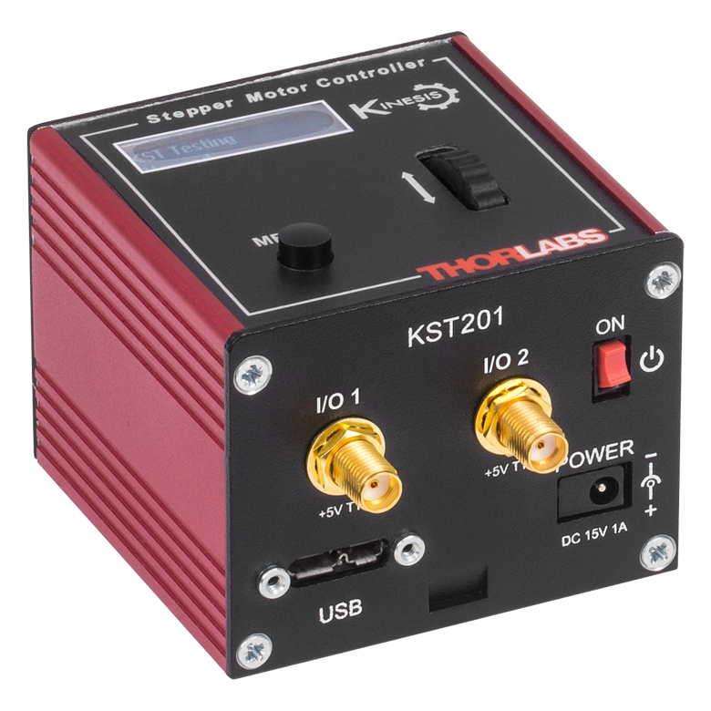
KST201
- 49 152 Microsteps per Revolution
- 15 V Output at 12 W
- Trapezoidal and
'S-Curve' Velocity Profiles
Features
- 25 mm (0.98") Travel
- Compact, Bi-Polar Stepper Motor Actuator
- Rugged, Thermally Matched, All-Steel Stage
- Right- or Left-Handed XYZ Configurable
Thorlabs' LNR25ZFS Stepper Motor Translation Stage offers 25 mm (0.98") of electronically controlled linear motion along a well-defined axis. This stage offers excellent stability and high horizontal load capacity, making it an ideal solution for all translation applications. This stage, based on the LNR25 TravelMax Manual Stage, has a rigid, all-steel design and heavy-duty cross-roller bearings for uniform performance over the entire range of motion. The performance of the stage is further enhanced by using thermally matched materials that ensure stable, smooth performance.
Compact Stepper Motor Actuator
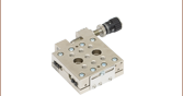
The LNR25ZFS is fitted with the ZFS25B Compact Stepper Motor Actuator, which provides smooth, precise linear motion control in a sleek, compact package. Powered by a small-diameter, dual-phase stepper motor, this actuator operates at speeds of up to 2.0 mm/s at maximum load. The non-rotating drive tip reduces wear and friction and improves smoothness of motion by removing rotational contact at the tip. If power is not supplied to the actuator, manual adjustment is accomplished using the rear-located thumbscrew.
This stepper motor provides sufficient torque for horizontal motions with loads up to 5 kg (11 lbs). The actuator allows very small step sizes over the entire travel range, delivering greater flexibility with a fine resolution. The design incorporates a 400:9 gear reduction head which, when combined with the 49 152 microsteps per revolution offered by the KST201 stepper motor driver, gives a theoretical travel per microstep of 0.46 nm (see the Specs tab for details).
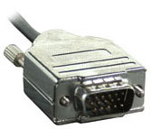
Hall effect limit switches prevent the unit from being overdriven and provide homing capability with an accuracy of <5.0 μm. The LNR25ZFS ships with 0.6 m (2 ft) of cable terminated in a 15-pin D-Type connector (see the Pin Diagrams tab) that is compatible with our KST201 stepper motor controller.
Please note that we do not recommend this stepper motor for vacuum applications; for this application we recommend using our Z925BV Vacuum-Compatible DC Motor Actuator.
| Motorized Linear Translation Stages | |
|---|---|
| 12 mm | Standard |
| 25 mm | Compact |
| Standard | |
| TravelMax | |
| 50 mm | Compact |
| Direct-Drive Servo | |
| TravelMax | |
| Long Travel: 100 mm to 300 mm | |
Wide Range of Mounting Options
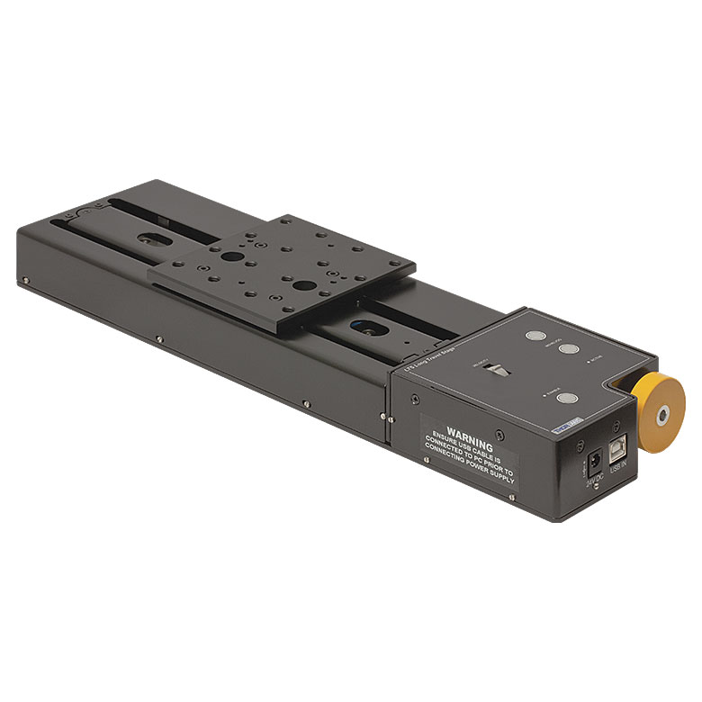
The TravelMax™ was designed with flexibility and functionality in mind. The top surface of the LNR25ZFS stage is equipped with an array of seven 1/4"-20 (M6) tapped holes to maximize the mounting options for moving components. Two through holes in the top platform give access to two 1/4" (M6) counterbored holes that allow the stage to be bolted directly to the work surface. The position of the actuator mounting blocks is easily reconfigured to allow left-hand or right-hand use.
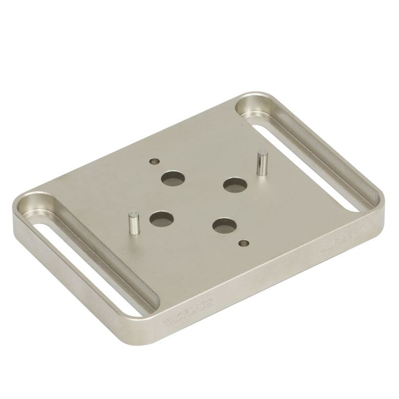
Click to Enlarge
Figure 1.1 LNR25P1 Base Plate
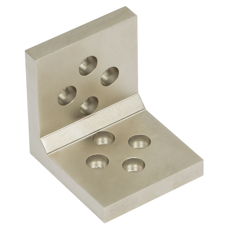
Click to Enlarge
Figure 1.2 LNR25P2 Angle Bracket
The LNR25P1 base plate, shown in Figure 1.1, provides additional mounting options and provides extra clearance between the stage and the work surface. Counterbored clearance holes match up to the tapped holes in the base of the stage, permitting mounting in two orthogonal orientations. This plate is compatible with both the imperial and metric versions of the LNR25ZFS(/M) stage. The plate measures 100 mm x 195 mm x 10 mm (3.9" x 7.7" x 0.47") [L x W x H], ships with two dowel pins, and includes four alignment holes to ensure mounting orthogonality.
Multiple LNR25ZFS series stages can be bolted together in XY, XZ, YZ, or XYZ configurations for applications where movement is required in more than one axis. The LNR25P2 angle bracket, shown in Figure 1.2, provides the vertical mounting necessary for movement in the Z direction. Again, this bracket is compatible with both the imperial and metric versions of the LNR25ZFS(/M) stage. The plate is shipped with four dowel pins and includes four alignment holes on each face to ensure orthogonality when mounting stages.
Controller Options
The LNR25ZFS stage is compatible with the KST201 K-Cube® Stepper Motor Controller, available below. The KST201 provides control for a single axis, with or without a PC. Thorlabs' Kinesis® software package provides out-of-the-box stage control from a PC and enables support for common programming interfaces like LabVIEW and LabWindows. Thorlabs' benchtop stepper motor controllers and legacy T-Cube™ TST001 stepper motor controllers cannot be used to drive the stage.
Resolution Calculation
The ZFS series of motors has 24 full steps per revolution, and when driven by the KST201 drivers, there are 2048 microsteps per full step, giving 49 152 microsteps per revolution of the motor. The output shaft of the motor goes into a 400:9 gear head. This requires the motor to rotate 44.445 times to rotate the 1.0 mm pitch lead screw one revolution. The end result is the lead screw advances by 1.0 mm.
Linear displacement of the lead screw per microstep:
Number of Microsteps x Gearbox Ratio = 49 152 x 44.445 = 2 184 560.64
The linear displacement of the lead screw per microstep is
1.0 mm / 2 184 560.64 = 0.46 x 10⁻⁶ mm = 0.46 nm
LNR25ZFS Specifications
| Specification | Value | |
|---|---|---|
| Translation | ||
| Travel | 25 mm (0.98") | |
| Absolute On-Axis Accuracy | 15 µm | |
| Bidirectional Repeatability | 3.0 µm | |
| Home Location Accuracy | <5.0 µm | |
| Max Velocitya | 2.0 mm/s | |
| Acceleration | 1.0 mm/s2 (Max) | |
| Stage | ||
| Horizontal Load Capacityb | 5 kg (11 lbs) | |
| Vertical Load Capacity | 0.5 kg (1.1 lbs) | |
| Runout Over Full Range | ±1.5 µm | |
| Bearings | Crossed Roller | |
| Body Construction | All Steel | |
| Actuator | ||
| Gearbox Ratio | 400:9 (Approx 44:1) | |
| Limit Switches | Hall Effect | |
| Lead Screw Pitch | 1.0 mm | |
| Motor Type | 2-Phase Stepper | |
| Microsteps per Revolution of the Motor |
24 Full Steps, 2048 µsteps per Full Step 49 152 µsteps per Revolution |
|
| Calculated Minimum Incremental Movement |
0.46 nm | |
| Cable Length | 0.6 m (2 ft) | |
| Connector | HDDB15 | |
| Compatible Controller | KST201 | |
| Physical | ||
| Operating Temperature | 5 to 40 °C (41 to 104 °F) | |
| Dimensions (L x W x H)c | 133.0 mm x 95.0 mm x 20.0 mm (5.24" x 3.74" x 0.79") |
|
| Weight (Including Actuator) | 0.73 kg (1.61 lbs) | |
Connector Pin Out
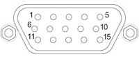
| Pin | Description | Pin | Description |
|---|---|---|---|
| 1 | Limit Ground | 8 | Reserved for Future Use |
| 2 | CCW Limit Switch | 9 | Reserved for Future Use |
| 3 | CW Limit Switch | 10 | Vcc (5 V DC) |
| 4 | Motor Phase B- | 11 | Reserved for Future Use |
| 5 | Motor Phase B+ | 12 | Reserved for Future Use |
| 6 | Motor Phase A- | 13 | Reserved for Future Use |
| 7 | Motor Phase A+ | 14 | Reserved for Future Use |
| 15 | Ground |
Software
Kinesis Version 1.14.58
The Kinesis Software Package, which includes a GUI for control of Thorlabs' Kinesis system controllers.
Also Available:
- Firmware Update Utilities
- Communications Protocol
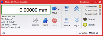
Figure 58A Kinesis GUI Screen
Thorlabs offers the Kinesis software package to drive our wide range of motion controllers. The software can be used to control devices in the Kinesis family, which covers a wide variety of motion controllers ranging from small, low-powered, single-channel drivers (such as the K-Cubes®) to high-power, multi-channel benchtop units and modular 19" rack nanopositioning systems (the MMR60x Rack System).
The Kinesis Software features .NET controls which can be used by 3rd party developers working in the latest C#, Visual Basic, LabVIEW™, or any .NET compatible languages to create custom applications. Low-level DLL libraries are included for applications not expected to use the .NET framework and APIs are included with each install. A Central Sequence Manager supports integration and synchronization of all Thorlabs motion control hardware.
By providing this common software platform, Thorlabs has ensured that users can mix and match any of our motion control devices in a single application, while only having to learn a single set of software tools. In this way, it is perfectly feasible to combine any of the controllers from single-axis to multi-axis systems and control all from a single, PC-based unified software interface.
The software package allows two methods of usage: graphical user interface (GUI) utilities for direct interaction with and control of the controllers 'out of the box', and a set of programming interfaces that allow custom-integrated positioning and alignment solutions to be easily programmed in the development language of choice.
| Posted Comments: | |
jan.obrzut
(posted 2018-11-08 15:20:57.543) I need to program the stage from Agilent VEE by sending a text cmd to serial port associated with the device. Will that be possible?
-Jan Obrzut rmiron
(posted 2018-11-15 07:29:21.0) Response from Radu at Thorlabs: Hello Jan. You can control the stage from Agilent VEE by using our APT serial communications protocol. However, the commands making up this protocol are not text commands, but rather arrays of hex bytes (int8 data type). The documentation of the aforementioned protocol can be found here: https://www.thorlabs.com/Software/Motion%20Control/APT_Communications_Protocol.pdf
I will contact you directly in case further assistance is required. wenzel.jakob
(posted 2018-01-09 19:44:22.76) I was wondering if the BSC* series (e.g. BSC201) controllers can also be used to drive the LNR25ZFS? AManickavasagam
(posted 2018-01-10 11:44:47.0) Response by Arunthathi at Thorlabs: Thank you for your query. The BSC series controllers are not compatible with LNR25ZFS. bluewhale
(posted 2017-05-06 16:02:58.2) I would like to know the uni-directional repeatability. The LNR25ZFS has very high Minimum incremental movement. But Bi-directional repeatability seems to be very high compared to its minimum incremental movement. Could you explain how this big difference comes from? and how long incremental movement do you guarantee for the uni-directional repeatability. bwood
(posted 2017-05-08 09:59:52.0) Response from Ben at Thorlabs: Thank you for your feedback. The minimum incremental movement we specify is a calculated figure based on the displacement of the leadscrew of one microstep of the motor of the ZFS actuator. While this figure is useful when considering how many microsteps there are in a given movement, it is, for many physical reasons, not realistic to achieve a single movement of 0.46 nm with the stage. The actual performance of the stage is influenced by issues such as low velocity stalling due to torque hotspots of the motor caused by imperfections of the lead screw bearings, the load of the stage and heat expansion. Thus we specify the bidirectional repeatability, which is a more realistic view of the performance of the stage. As the stage has backlash correction, the uni-directional repeatability will be similar to the bi-directional repeatability. michail.symeonidis
(posted 2016-05-03 17:48:58.24) I would like to ask if the orientation of the stage effects the (vertical) load capacity. To be more precise what is the load capacity if the stage is mounted perpendicular to the x-y plane, but travels along the y (not z) axis.
Thank you for your time and support msoulby
(posted 2016-05-04 10:06:57.0) Response from Mike at Thorlabs: The vertical load capacity is dictated by the actuator used, rather than the stage bearings. So, the horizontal load capacity will apply for horizontal motion, irrespective of whether the stage is mounted on its edge or on its base. The vertical load capacity applies to vertical movement only. haitao
(posted 2015-04-07 06:52:21.457) Dear Sr/Madam,
I am finding a vacuum compatible stage with low profile and travel length. I saw this stage is made of steel, so I wonder whether it is vacuum compatible. Do you have custom vacuum compatible stages? If you have another stage which is vacuum compatible, please tell me. Looking forward to your response! Thanks!
Best,
Haitao
Harvard University bhallewell
(posted 2015-04-09 06:53:27.0) Response from Ben at Thorlabs: Thank you for your question here. In terms of exclusively designed high vacuum compatible products, we produce the Z825BV DC Servo vacuum-compatible actuator which can be fitted with a Custom prepared PT1 stage for use in such an environment. Further details of this can be found in the following link.
http://www.thorlabs.com/newgrouppage9.cfm?objectgroup_id=1883
The LNR25ZFS/M is coated with a red anodised finish & this would not be suitable for vacuum use. |
Motorized Linear Translation Stages
Thorlabs' motorized linear translation stages are offered in a range of maximum travel distances, from a stage with 20 µm of piezo translation to our 600 mm direct drive stage. Many of these stages can be assembled in multi-axis configurations, providing XY or XYZ translation. For fiber coupling applications, please see our multi-axis stages, which offer finer adjustment than our standard motorized translation stages. In addition to motorized linear translation stages, we offer motorized rotation stages and goniometers. We also offer manual translation stages.
Piezo Stages
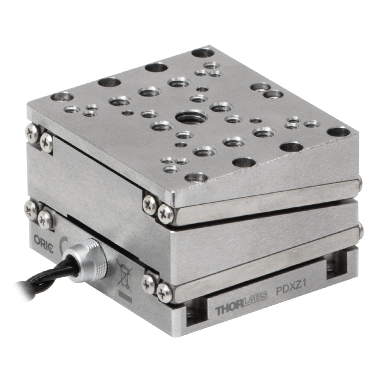
These stages incorporate piezoelectric elements in a variety of drive mechanisms. ORIC® stages incorporate piezo inertia drives that use "stick-slip" friction properties to obtain extended travel ranges. Our Nanoflex™ translation stages use standard piezo chips along with manual actuators. Elliptec® stages use resonant piezo motors to push and pull the moving platform through resonant elliptical motion. Our LPS710E z-axis stage features a mechanically amplified piezo design and includes a matched controller.
| Piezoelectric Stages | ||||||
|---|---|---|---|---|---|---|
| Product Family | ORIC® PDXZ1 Closed-Loop 4.5 mm Vertical Stage |
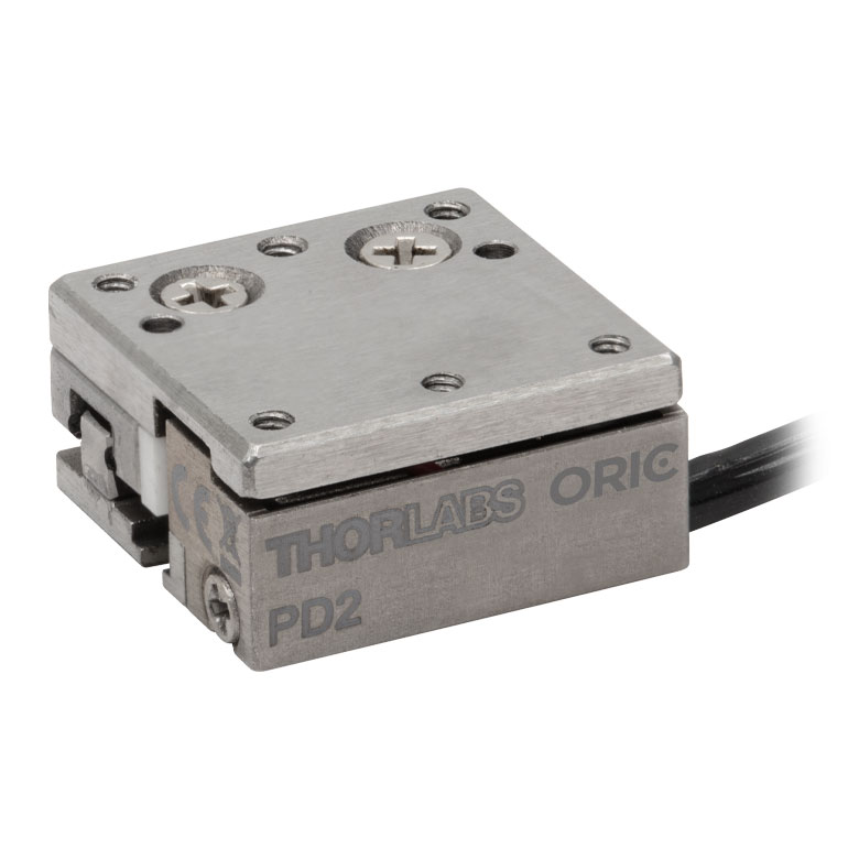
ORIC® PD2 Open-Loop 5 mm Stage |
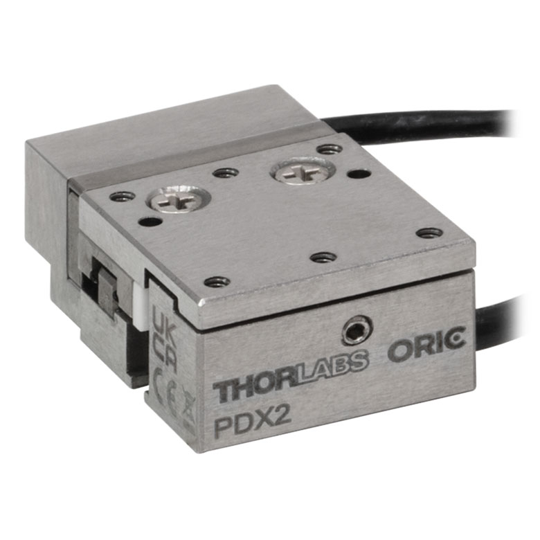
ORIC® PDX2 Closed-Loop 5 mm Stage |
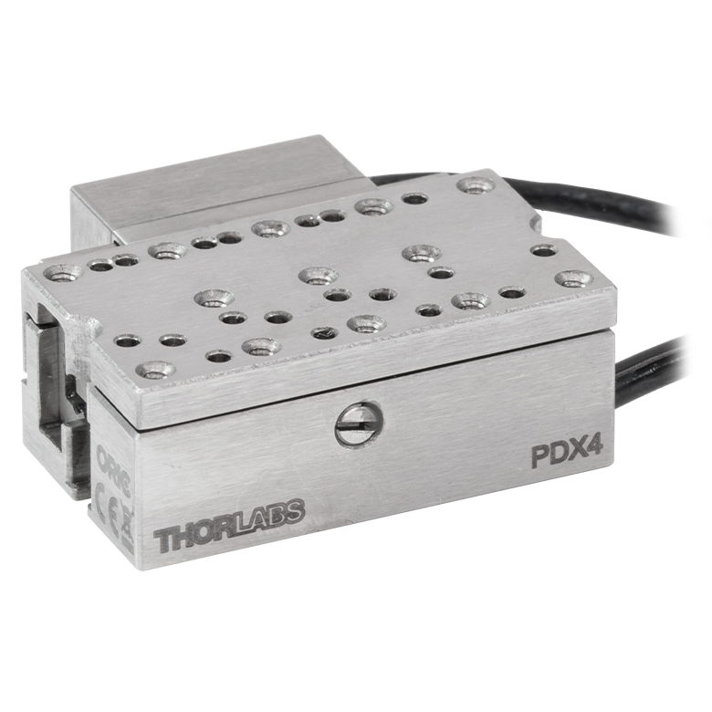
ORIC® PDX4 Closed-Loop 12 mm Stage |
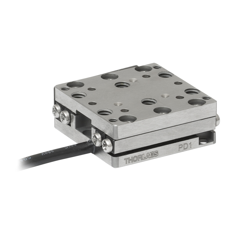
ORIC® PD1 Open-Loop 20 mm Stage |
ORIC® PD1D Open-Loop 20 mm Monolithic XY Stage |
| Click Photo to Enlarge |
 |
 |
 |
 |
 |
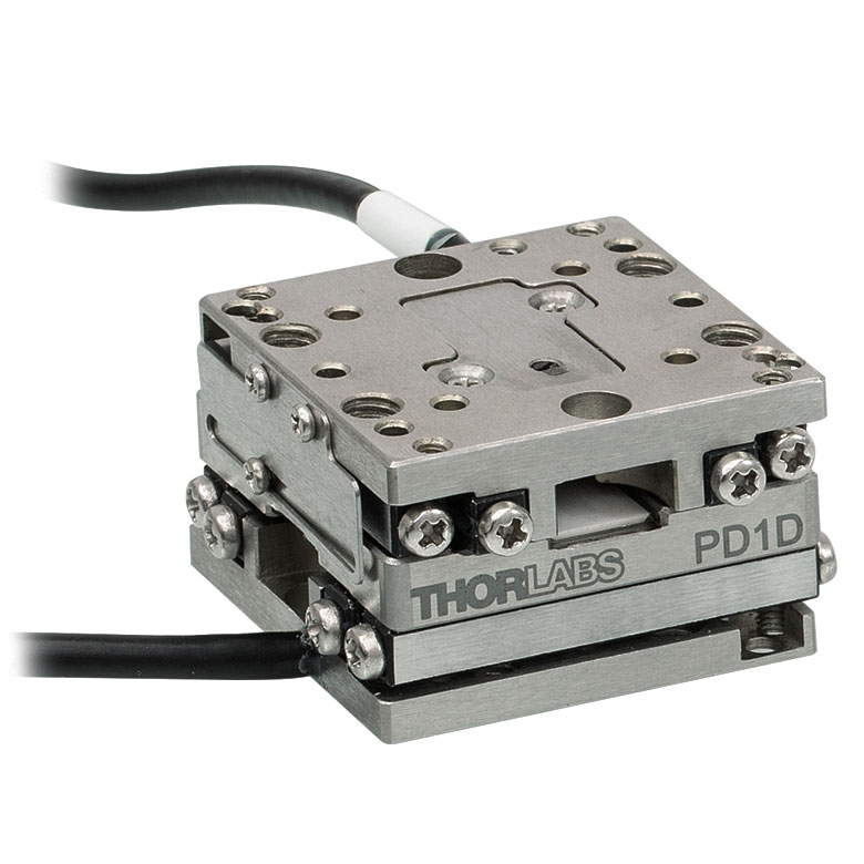 |
| Travel | 4.5 mm | 5 mm | 12 mm | 20 mm | ||
| Speed | 1 mm/s (Typ.)a | 10 mm/s (Typ. Max)b | 8 mm/s (Typ.)c | 15 mm/s (Typ.)a,c | 3 mm/s (Typ. Max)d | |
| Drive Type | Piezoelectric Inertia Drive | |||||
| Possible Axis Configurations | Z | X, XY, XYZ | XY, XYZ | |||
| Mounting Surface Size |
45.0 mm x 42.0 mm | 13.0 mm x 13.0 mm | 13.0 mm x 23.0 mm | 30.0 mm x 30.0 mm | ||
| Additional Details | ||||||
| Piezoelectric Stages | ||||||
|---|---|---|---|---|---|---|
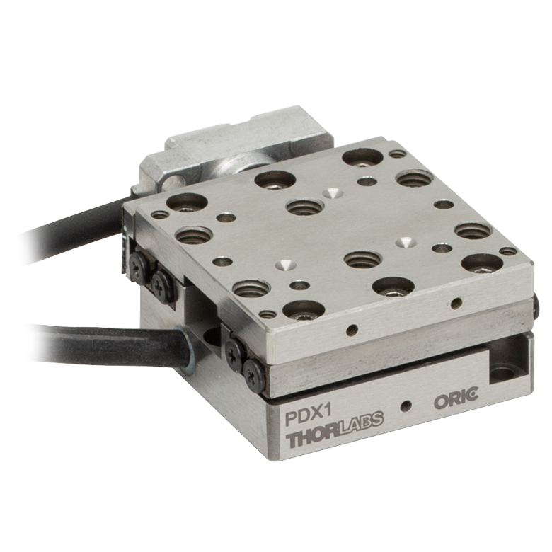
| Product Family | ORIC® PDX1 Closed-Loop 20 mm Stage |
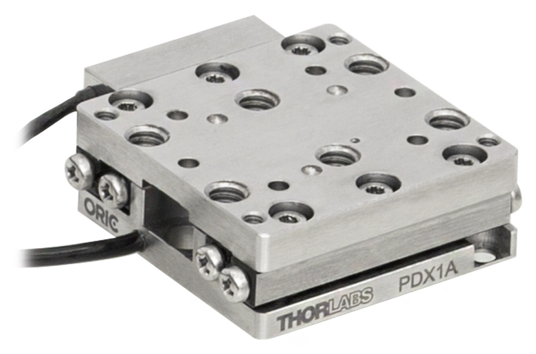
ORIC® PDX1A Closed-Loop 20 mm Stage Low-Profile |
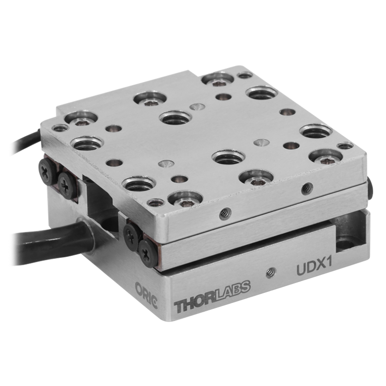
ORIC® UDX1 Ultrasonic Closed-Loop 20 mm Stage |
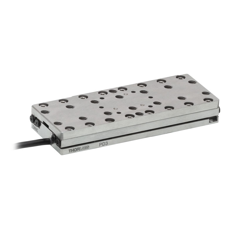
ORIC® PD3 Open-Loop 50 mm Stage |
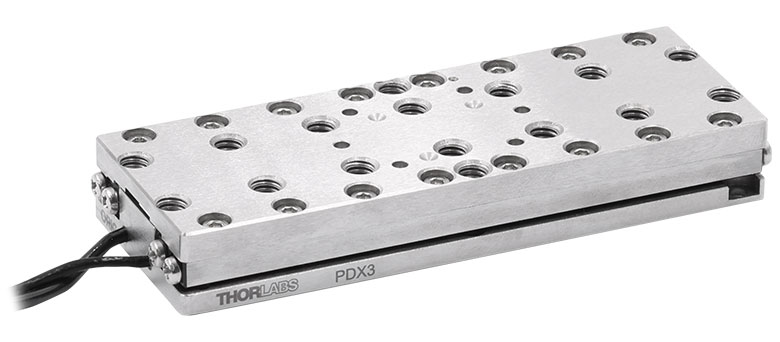
ORIC® PDX3 Closed-Loop 50 mm Stage |
|
| Click Photo to Enlarge |
 |
 |
 |
 |
 |
|
| Travel | 20 mm | 50 mm | ||||
| Speed | 20 mm/s (Typ. Max)a | 10 mm/s (Typ.)b | 100 mm/s (Typ. Max)c | 10 mm/sd | 10 mm/s (Typ. Max)b | |
| Drive Type | Piezoelectric Inertia Drive | Ultrasonic Piezoelectric Drive | Piezoelectric Inertia Drive | |||
| Possible Axis Configurations | X, XY, XYZ | |||||
| Mounting Surface Size |
30.0 mm x 30.0 mm | 80.0 mm x 30.0 mm | ||||
| Additional Details | ||||||
| Piezoelectric Stages | |||||||
|---|---|---|---|---|---|---|---|
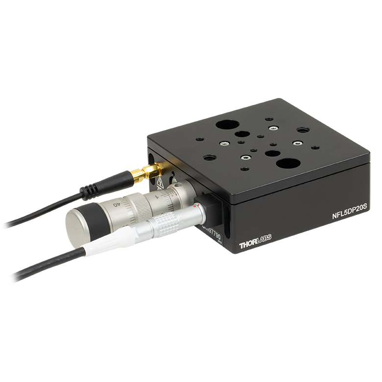
| Product Family | Nanoflex™ 20 µm Stage with 5 mm Actuator |
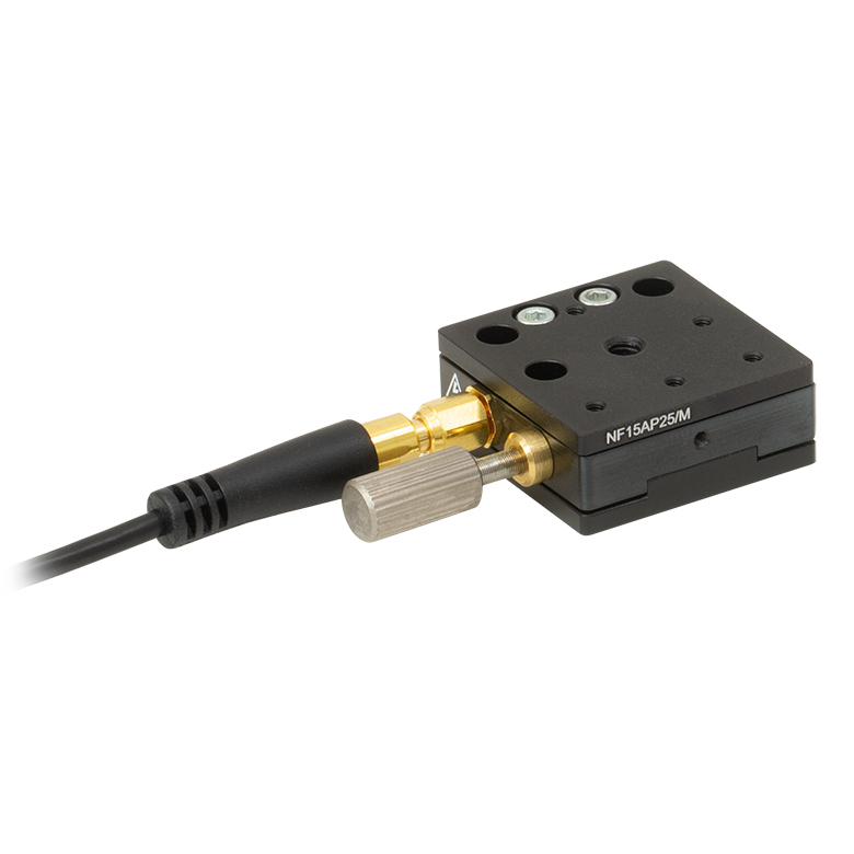
Nanoflex™ 25 µm Stage with 1.5 mm Actuator |
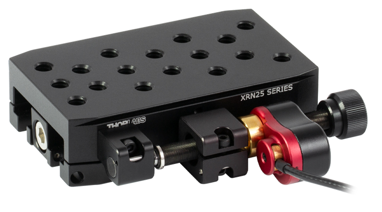
Compact Modular XRN25X 25 mm Stage |
Modular XR25X 25 mm Stage |
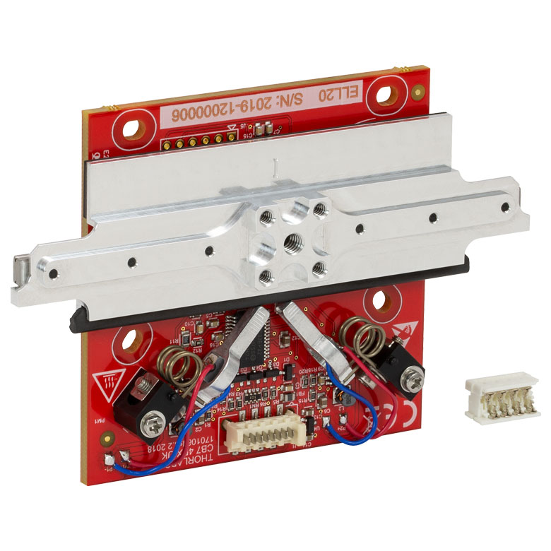
Elliptec® 28 mm Stage | Elliptec® 60 mm Stage | LPS710E 1.1 mm Vertical Stage |
| Click Photo to Enlarge |
 |
 |
 |
 |
 |
 |
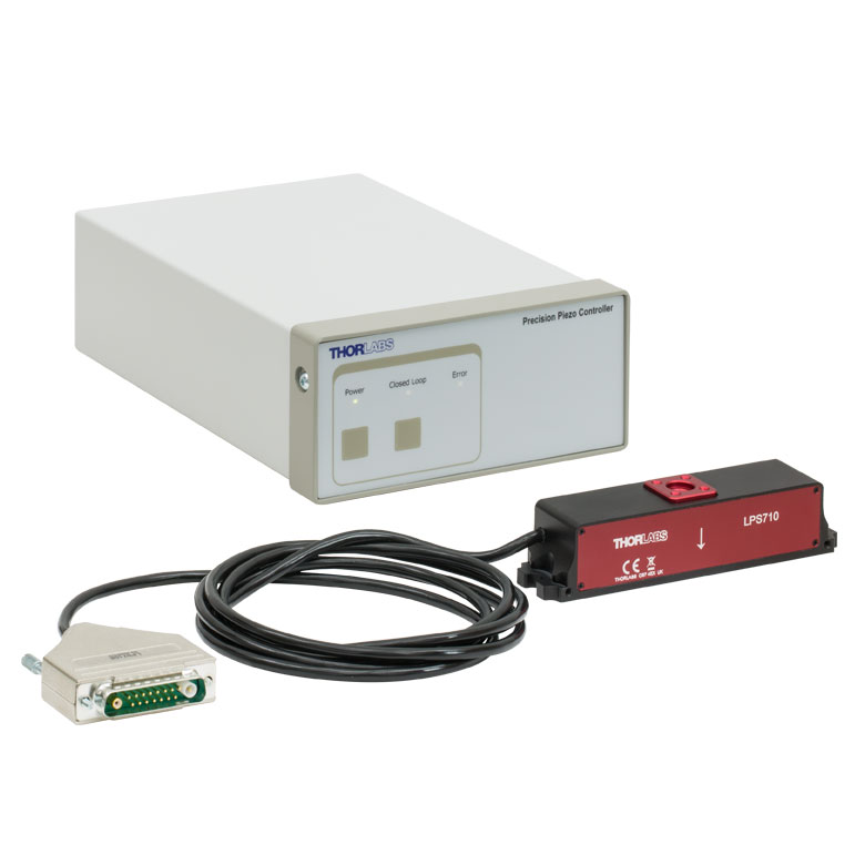 |
| Travel | 20 µm + 5 mm Manual | 25 µm + 1.5 mm Manual | 25 mm | 28 mm | 60.0 mm | 1.1 mm | |
| Maximum Velocity | - | ≤3.6 mm/mina | 180 mm/s | 90 mm/s | - | ||
| Drive Type | Piezo with Manual Actuator | Piezoelectric Inertia Drive | Resonant Piezoelectric Motor | Amplified Piezo | |||
| Possible Axis Configurations | X, XY, XYZ | X, XY, YZ, XZ, XYZ | X | Z | |||
| Mounting Surface Size | 75 mm x 75 mm | 30 mm x 30 mm | 85.0 mm x 50.7 mm | 110.0 mm x 75.7 mm | 15 mm x 15 mm | 21 mm x 21 mm | |
| Additional Details | |||||||
Stepper Motor Stages
These translation stages feature removable or integrated stepper motors and long travel ranges up to 300 mm. Many of these stages either have integrated multi-axis capability (PLSXY) or can be assembled into multi-axis configurations (PLSX, LNR Series, NRT Series, and LTS Series stages). The MLJ150 stage also offers high load capacity vertical translation.
| Stepper Motor Stages | |||||
|---|---|---|---|---|---|
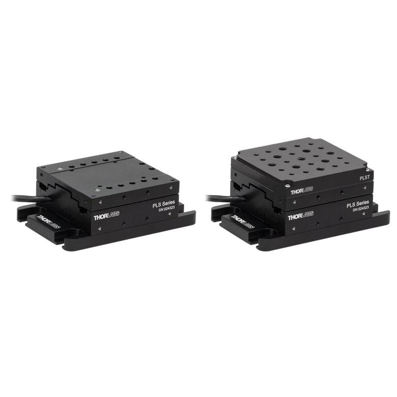
| Product Family | PLSX with and without PLST(/M) Top Plate 1" Stage |
PLSXY with and without PLST(/M) Top Plate 1" Stage |
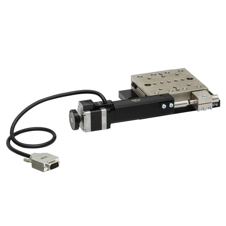
LNR Series 25 mm Stage |
LNR Series 50 mm Stage |
|
| Click Photo to Enlarge |
 |
 |
 |
 |
|
| Travel | 1" | 25 mm | 50 mm | ||
| Maximum Velocity | 7.0 mm/s | 2.0 mm/s | 50 mm/s | ||
| Possible Axis Configurations |
X, XY | X, XY, XYZ | X, XY, XYZ | ||
| Mounting Surface Size |
3" x 3" | 60 mm x 60 mm | 100 mm x 100 mm | ||
| Additional Details | |||||
| Stepper Motor Stages | |||||||
|---|---|---|---|---|---|---|---|
| Product Family | NRT Series 100 mm Stage |
NRT Series 150 mm Stage |
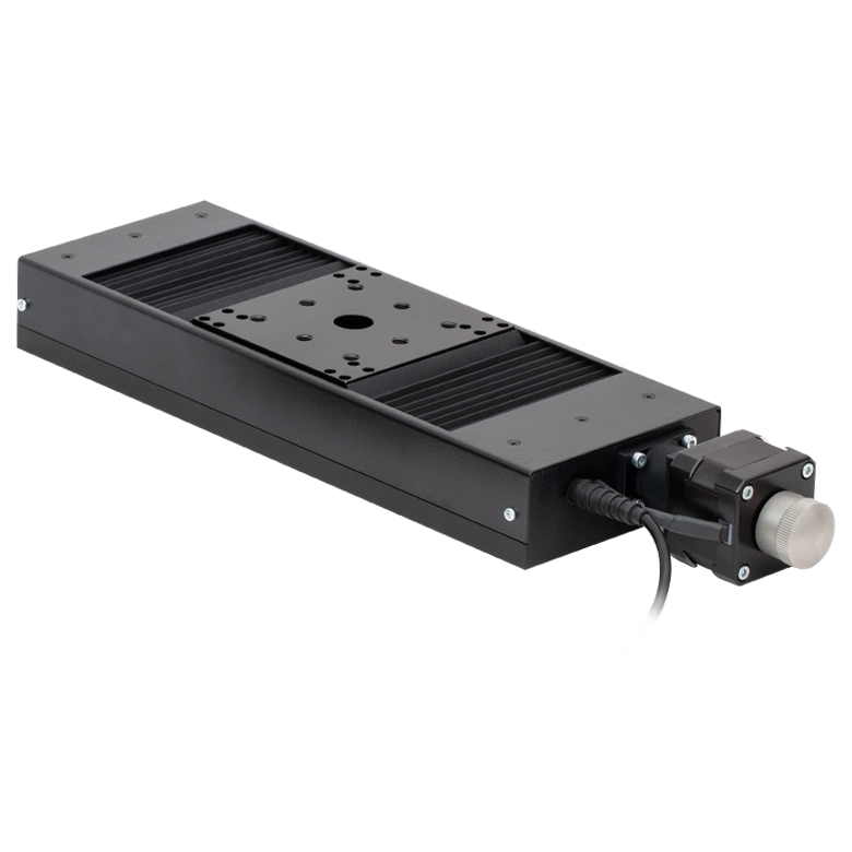
LTS Series 150 mm Stage |
LTS Series 300 mm Stage |
LTS Series 450 mm Stage |
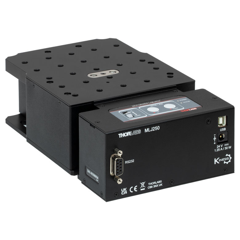
MLJ250 50 mm Vertical Stage |
|
| Click Photo to Enlarge |
 |
 |
 |
 |
 |
 |
|
| Travel | 100 mm | 150 mm | 150 mm | 300 mm | 400 mm | 50 mm | |
| Maximum Velocity | 30 mm/s | 50 mm/s | 3.0 mm/s | ||||
| Possible Axis Configurations |
X, XY, XYZ | X, XY, XYZ | X, XY | Z | |||
| Mounting Surface Size |
84 mm x 84 mm | 100 mm x 90 mm | 148 mm x 131 mm | ||||
| Additional Details | |||||||
DC Servo Motor Stages
Thorlabs offers linear translation stages with removable or integrated DC servo motors. These stages feature low profiles and many can be assembled in multi-axis configurations.
| DC Servo Motor Stages | ||||
|---|---|---|---|---|
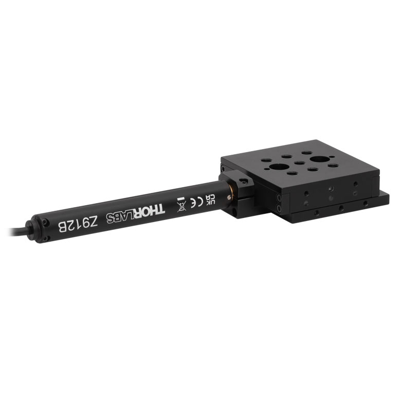
| Product Family | MT Series 12 mm Stages |
PT Series 25 mm Stages |
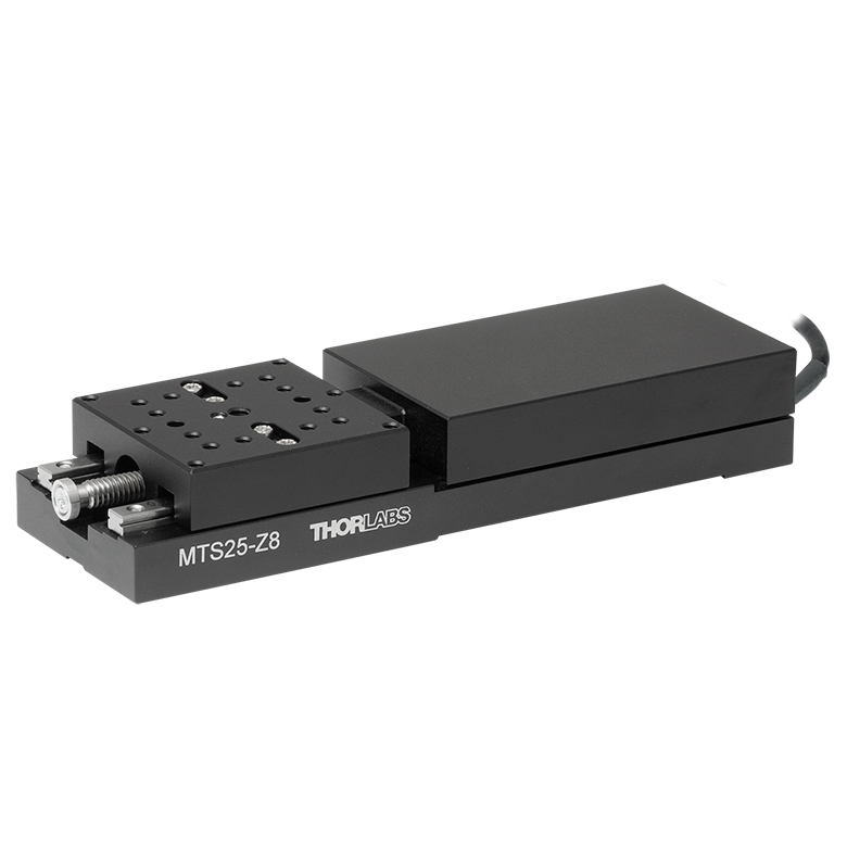
MTS Series 25 mm Stage |
MTS Series 50 mm Stage |
| Click Photo to Enlarge |
 |
 |
 |
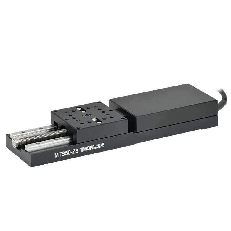 |
| Travel | 12 mm | 25 mm | 25 mm | 50 mm |
| Maximum Velocity | 2.6 mm/s | 2.4 mm/s | ||
| Possible Axis Configurations | X, XY, XYZ | X, XY, XYZ | ||
| Mounting Surface Size |
61 mm x 61 mm | 101.6 mm x 76.2 mm | 43 mm x 43 mm | |
| Additional Details | ||||
| DC Servo Motor Stages | ||||
|---|---|---|---|---|
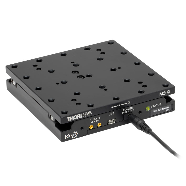
| Product Family | M30 Series 30 mm Stage |
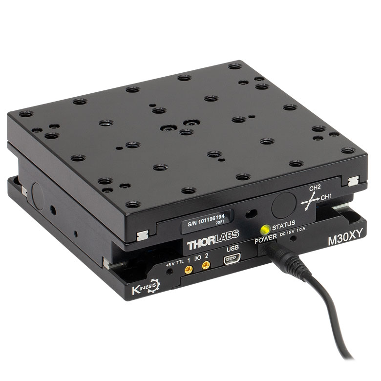
M30 Series 30 mm Monolithic XY Stage |
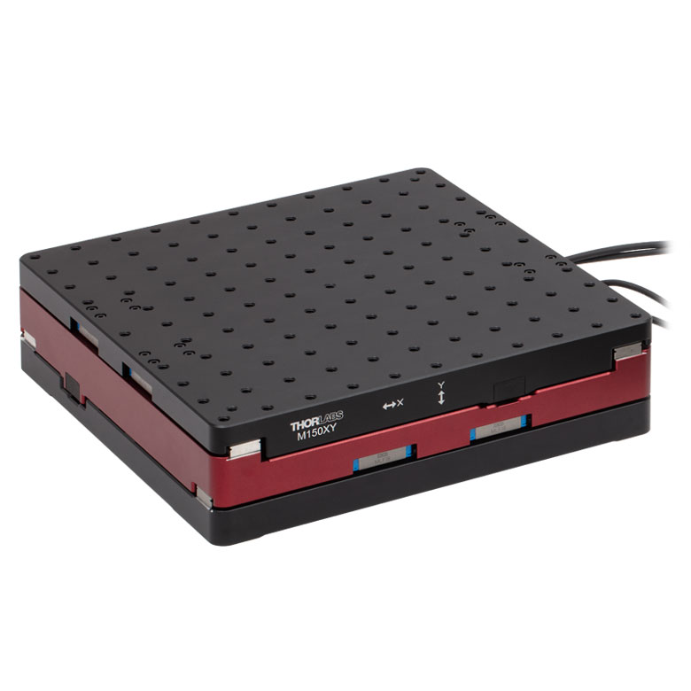
M150 Series 150 mm XY Stage |
KVS30 30 mm Vertical Stage |
| Click Photo to Enlarge |
 |
 |
 |
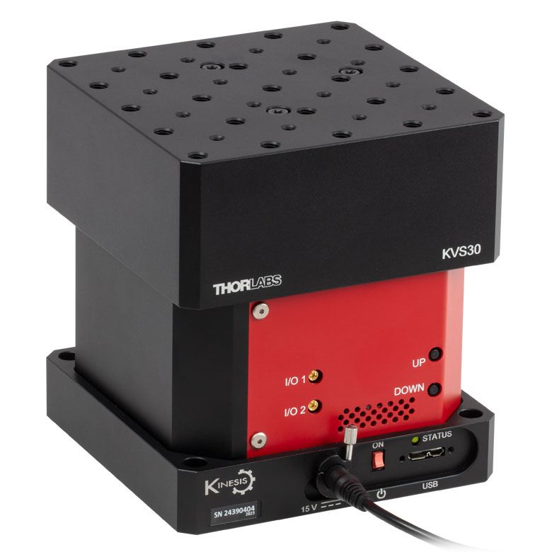 |
| Travel | 30 mm | 150 mm | 30 mm | |
| Maximum Velocity | 2.4 mm/s | X-Axis: 170 mm/s Y-Axis: 230 mm/s |
8.0 mm/s | |
| Possible Axis Configurations | X, Z | XY, XZ | XY | Z |
| Mounting Surface Size |
115 mm x 115 mm | 272.4 mm x 272.4 mm | 116.2 mm x 116.2 mm | |
| Additional Details | ||||
Direct Drive Stages
These low-profile stages feature integrated brushless DC servo motors for high speed translation with zero backlash. When no power is applied, the platforms of these stages have very little inertia and are virtually free running. Hence these stages may not be suitable for applications where the stage's platform needs to remain in a set position when the power is off. We do not recommend mounting these stages vertically.
| Direct Drive Stages | |||||
|---|---|---|---|---|---|
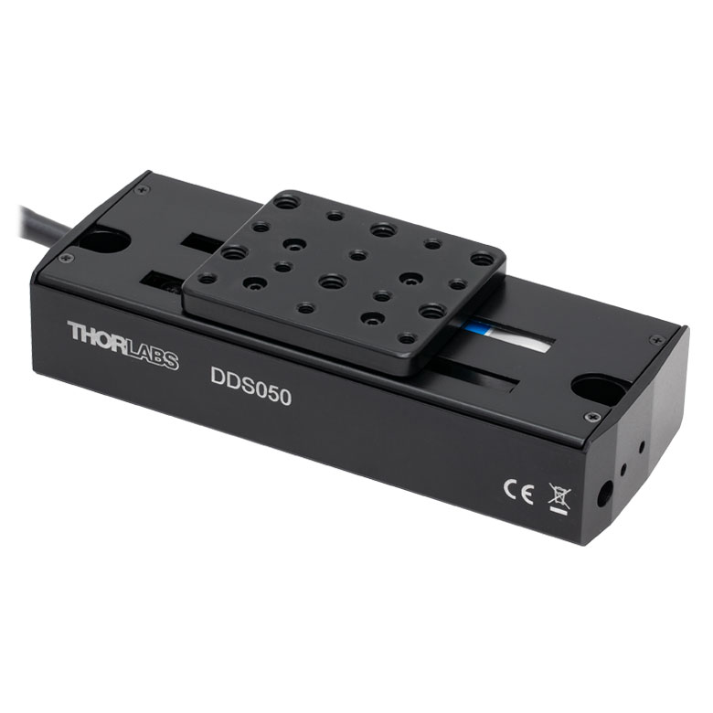
| Product Family | DDS Series 50 mm Stage |
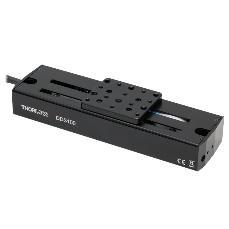
DDS Series 100 mm Stage |
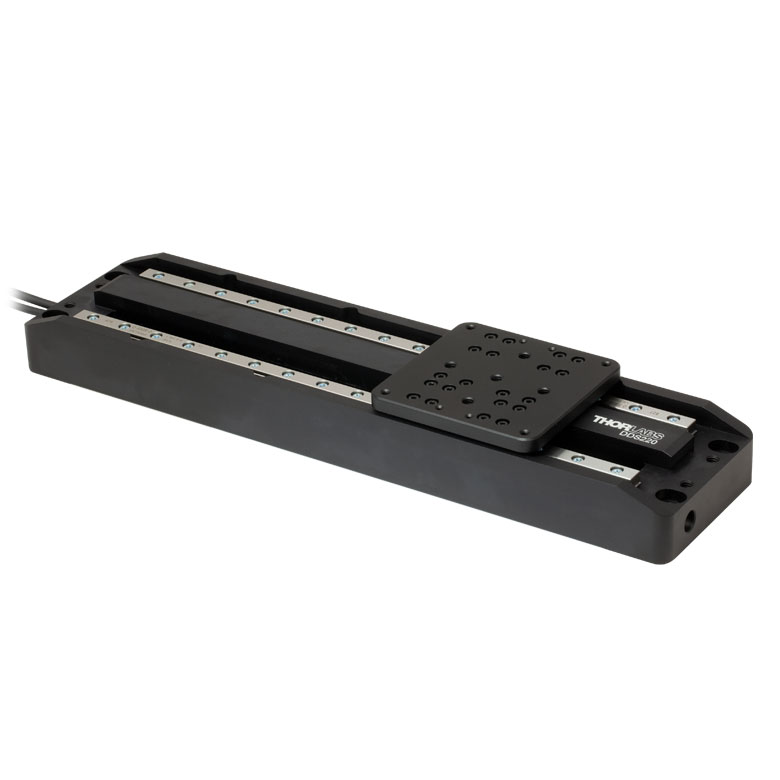
DDS Series 220 mm Stage |
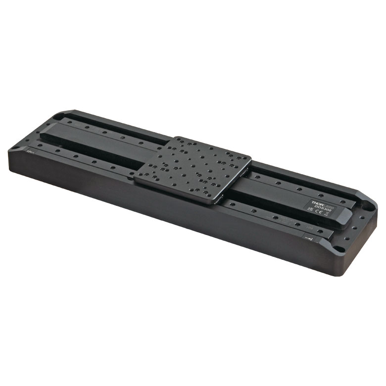
DDS Series 300 mm Stage |
DDS Series 600 mm Stage |
| Click Photo to Enlarge |
 |
 |
 |
 |
 |
| Travel | 50 mm | 100 mm | 220 mm | 300 mm | 600 mm |
| Maximum Velocity | 500 mm/s | 300 mm/s | 400 mm/s | 400 mm/s | |
| Possible Axis Configurations | X, XY | X, XY | X | X | |
| Mounting Surface Size | 60 mm x 52 mm | 88 mm x 88 mm | 120 mm x 120 mm | ||
| Additional Details | |||||
 Stepper Motor Translation Stage")
 Zoom
Zoom- LNR25ZFS(/M) Provides 25 mm (0.98") of Motorized Motion
- Stepper Motor Actuator for Smooth, Precise Linear Motion
- Controller and Power Supply Sold Separately
Thorlabs' LNR25ZFS(/M) Stepper Motor Translation Stage provides 25 mm (0.98") of linear motion. An array of seven 1/4"-20 (M6) tapped holes allows easy integration with a wide variety of common optomechanical setups. The stage features rigid, all-steel construction and heavy-duty cross-roller bearings for excellent stability and high load capacity. The stage requires a controller unit and power supply to operate. For this purpose, we recommend our KST201 K-Cube® Stepper Motor Controller, which is described in more detail below. A mounting base plate and a vertical mounting bracket for the stage are available below.

 Zoom
Zoom- Mount LNR25ZFS(/M) Stages and Build Multi-Axis Configurations
- Universal Accesories for Imperial and Metric Stages
- Dowel Pins for Accurate Alignment
The LNR25P1 Base Plate and LNR25P2 Angle Bracket are mounting accesories for the LNR25ZFS(/M) Stage. The LNR25P1 base plate has four counterbored clearance holes for mounting the LNR25ZFS in two orthogonal orientations. The LNR25P2 angle bracket provides a vertical mounting surface for construction of an XZ, YZ, or XYZ configuration. These mounting accessories are compatible with both the imperial and metric versions of the translation stage.

 Zoom
Zoom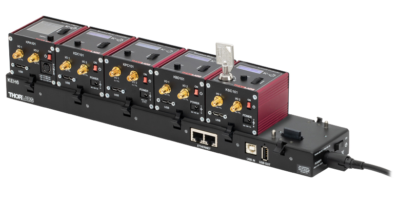
Click to Enlarge
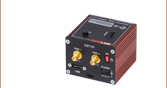
Figure G3.1 KEH6 Ethernet and USB Controller Hub
(Sold Separately) with Installed K-Cube Modules
- Front Panel Velocity Wheel and Digital Display for Controlling Motorized Stages or Actuators
- Two Bidirectional Trigger Ports to Read or Control External Equipment
- Interfaces with Computer Using Included USB Cable
- Fully Compatible with the Kinesis® Software Package
- Compact Footprint: 60.0 mm x 60.0 mm x 49.2 mm (2.36" x 2.36" x 1.94")
- Power Supply Not Included (See Below)
Thorlabs' KST201 K-Cube® Stepper Motor Controller provides local and computerized control of a single motor axis. It features a top-mounted control panel with a velocity wheel that supports variable-speed bidirectional control with forward and reverse jogging as well as position presets. The digital display on the top panel includes a backlight that can be dimmed or turned off using the top panel menu options. The front of the unit contains two bidirectional trigger ports that can be used to read a 5 V external logic signal or output a 5 V logic signal to control external equipment. Each port can be independently configured.
The unit is fully compatible with our Kinesis software package. Please see the Kinesis Software tab for more information.
Please note that this controller does not ship with a power supply. Compatible power supplies are listed below.

 Zoom
Zoom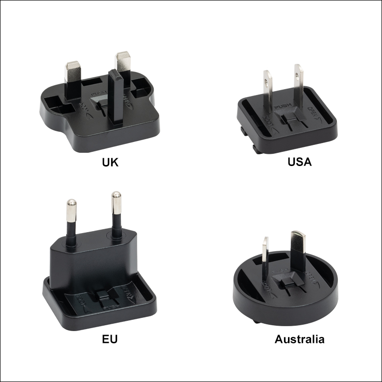
Click for Details
Figure 780B Each KPS201 power supply includes one region-specific adapter, which can be selected upon checkout.
Click to Enlarge
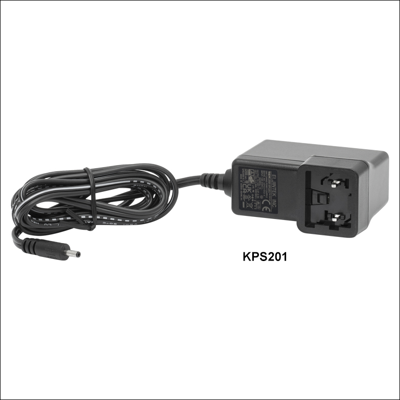
Figure 780A The KPS201 Power Supply Unit
- Individual Power Supply
- KPS201: For K-Cubes® or T-Cubes™ with 3.5 mm Jacks
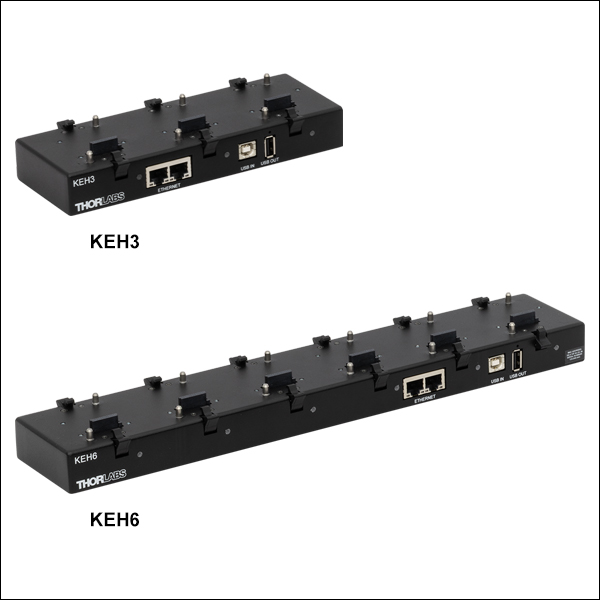
- Ethernet and USB Controller Hubs Provide Power and Communications
- KEH3: For Up to Three K-Cubes or T-Cubes
- KEH6: For Up to Six K-Cubes or T-Cubes
The KPS201 power supply outputs +15 VDC at up to 2.66 A and can power a single K-Cube or T-Cube with a 3.5 mm jack. It plugs into a standard wall outlet.
The KEH3 and KEH6 Controller Hubs contain a fully compliant USB 2.0 hub circuit and provide all communications and power distribution for up to three (Item # KEH3) or six (Item # KEH6) K-Cubes or T-Cubes (KAP101 or KAP102 adapters are needed for T-Cubes), using only a single power connection. Additionally, the hubs have two Ethernet connection ports. The second Ethernet port or USB OUT port can be connected to the input on another Controller Hub to allow multiple Controller Hub connections while still only requiring a single Ethernet or USB cable from the host PC. The hubs draw a maximum current of 4.6 A; please verify that the cubes being used do not require a total current of more than 4.6 A.
For more information on the controller hubs, see the full web presentation.