 Products Home / Motorized Stages / Pitch/Yaw Stages and Goniometers / 1- and 2-Axis Motorized Goniometer Stages
1- and 2-Axis Motorized Goniometer Stages

- Pure Rotational Motion About a Fixed Point Above the Stage
- 1° Graduation Markings on Side
- Includes DC Motor Actuators for Easy Automation
GNL20-Z9
GNL18-Z9
GNL10-Z9
Actual Cable Length
is 1.59' (0.485 m)


Please Wait

| Item # | GNL10(/M)-Z9 | GNL18(/M)-Z9 | GNL20(/M)-Z9 |
|---|---|---|---|
| Distance to Point of Rotation |
1.00" (25.4 mm) | 1.75" (44.5 mm) | 1.00" (25.4 mm) |
| Rotation | ±8° | ±5° | ±8° / ±5° |
| Accuracy | 10 arcmin (0.17°) | ||
| Load Capacity | 0.50 lbs (0.23 kg) | ||
| Goniometer Dimensions (W x D x H) |
1.50" x 1.50" x 0.75" (38.1 mm x 38.1 mm x 19.1 mm) |
1.50" x 1.50" x 1.50" (38.1 mm x 38.1 mm x 38.1 mm) |
|
| Base Plate Dimensions (W x D x H) |
Imperial Goniometers: 1.50" x 2.50" x 0.20" | ||
| Metric Goniometers: 38.1 mm x 62.7 mm x 5.1 mm | |||
| Body Material | Anodized Aluminum | ||
Features
- Pure Rotational Motion About a Virtual Point
- 1° Graduation Marks on Side
- Backlash-Free Spring-Loaded Design
- Fully Lockable
- Single Axis and XY Configurations
- DC Motorized with Z912B Actuator
- Manual Goniometer Stages Also Available
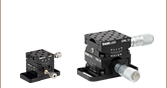
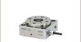
A goniometer or goniometric stage is a device used to rotate an object precisely, within a small angular range, about a fixed point in space. Goniometers are similar to linear stages, but, rather than providing linear movement, the stage partially rotates about a fixed point above the mounting surface of the stage. In our two product lines, the distance from the point of rotation to the mounting surface was designed so that two different goniometer models may be stacked in an XY configuration and both stages will rotate about the same point. Our motorized goniometers use our Z912B DC Servo Actuator for enhanced, automated, angular positioning of the top plate.
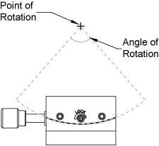
Our goniometers offer unobstructed, pure rotational motion about their point of rotation over the angle of rotation (see image to the right). The compact, stackable design allows one model to be fastened to the top plate of another aligning their points of rotation. In the GNL series, the GNL10(/M)-Z9 mounts atop the GNL18(/M)-Z9. These two axis stage setups can be purchased as a single package [Item # GNL20(/M)-Z9].
The precision dovetail design, accompanied by a backlash-free lead screw and a vernier scale, provides accurate and repeatable positioning. A side mounted setscrew can be used to lock the platform in position.
The GNL series goniometers provide an array of twelve 4-40 (M2.5) and sixteen 6-32 (M4) taps for mounting. See below for mounting hole positions.
The KDC101 DC Servo Controller is the ideal driver for the Z9 series actuators. The unit is fully compatible with our Kinesis software package, which can be downloaded here. Please see the Kinesis Software tab for more information.
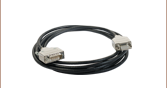
The Z912B DC servo motors shipped with these stages are provided with 1.59' (0.485 m) of cable. An 8' (2.5 m) extension cable, PAA632, is also available.
Click to Enlarge
Goniometer Dimensions

Click for Details
Mounting Options
Goniometer Specifications
| Item # | GNL10(/M) | GNL18(/M) | GNL20(/M) |
|---|---|---|---|
| Distance to Point of Rotation |
1.00" (25.4 mm) | 1.75" (44.5 mm) | 1.00" (25.4 mm) |
| Rotation | ±8° | ±5° | ±8° / ±5° |
| Accuracy | 10 arcmin (0.17°) | ||
| Load Capacity | 0.50 lbs (0.23 kg) | ||
| Goniometer Dimensions (W x D x H) |
1.50" x 1.50" x 0.75" (38.1 mm x 38.1 mm x 19.1 mm) |
1.50" x 1.50" x 1.50" (38.1 mm x 38.1 mm x 38.1 mm) |
|
| Base Plate Dimensions (W x D x H) |
Imperial Goniometers: 1.50" x 2.50" x 0.20" | ||
| Metric Goniometers: 38.1 mm x 62.7 mm x 5.1 mm | |||
| Body Material | Anodized Aluminum | ||
Actuator Specifications
| Item # | Z912B |
|---|---|
| Travel | 12 mm (0.47") |
| Motor Type | DC Servo |
| Max Recommended Current | 240 mA |
| Lead Screw Pitch | 1 mm |
| Calculated Resolutiona | 29 nm |
| Homing Repeatability | ±6 µm |
| Uncompensated Backlash | 13 µm |
| Residual Backlash After Compensationb | 0.7 µm |
| Feedback | Motor Mounted Rotary Encoder 512 counts/rev of the motor 34,555 counts/rev of lead screw |
| Planetary Gearhead Ratio | 67.49:1 |
| Limit Switches | Electromechanical |
| Max Speedc | 2.6 mm/s |
| Operating Temperature | 41 - 104 °F (5 - 40 °C) |
| Cable Length | 1.59' (0.485 m) |
| Compatible Controller | KDC101 |
There are 512 encoder counts per revolution of the motor. The output shaft of the motor goes into a 67.49:1 planetary gear head. This requires the motor to rotate 67.49 times to rotate the 1.0 mm pitch lead screw one revolution. The end result is the lead screw advances by 1.0 mm.
The linear displacement of the actuator per encoder count is given by
512 x 67.49 = 34,555 encoder counts per revolution of the lead screw,
whereas the linear displacement of the lead screw per encoder count is given by
1.0 mm / 34,555 counts = 2.9 x 10⁻⁵ mm (29 nm).
Z912B DC Servo Motor Output
D-type Male
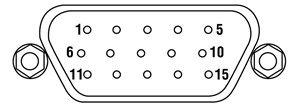
| Pin | Description | Pin | Description |
|---|---|---|---|
| 1 | Ground (Limit and Vcc) | 9 | Resistive Identification |
| 2 | Forward Limit | 10 | +5 VDC |
| 3 | Reverse Limit | 11 | Encoder Channel A |
| 4 | Reserved for Future Use | 12 | Reserved for Future Use |
| 5 | Motor (-) | 13 | Encoder Channel B |
| 6 | Reserved for Future Use | 14 | Pin 2 Ident EEPROM |
| 7 | Motor (+) | 15 | Pin 1 Ident EEPROM |
| 8 | Reserved for Future Use |

Click to Enlarge
GNL10-Z9 Packaging

| Item # | % Weight Reduction |
CO2-Equivalent Reductiona |
|---|---|---|
| GNL10-Z9 | 7.92% | 0.05 kg |
| GNL10/M-Z9 | 7.92% | 0.09 kg |
| GNL18-Z9 | 29.80% | 0.17 kg |
| GNL18/M-Z9 | 7.92% | 0.12 kg |
Smart Pack
- Reduce Weight of Packaging Materials
- Increase Usage of Recyclable Packing Materials
- Improve Packing Integrity
- Decrease Shipping Costs
Thorlabs' Smart Pack Initiative is aimed at waste minimization while still maintaining adequate protection for our products. By eliminating any unnecessary packaging, implementing packaging design changes, and utilizing eco-friendly packaging materials for our customers when possible, this initiative seeks to improve the environmental impact of our product packaging. Products listed above are now shipped in re-engineered packaging that minimizes the weight and the use of non-recyclable materials.b As we move through our product line, we will indicate re-engineered packages with our Smart Pack logo.
Software
Kinesis Version 1.14.52
The Kinesis Software Package, which includes a GUI for control of Thorlabs' Kinesis system controllers.
Also Available:
- Communications Protocol
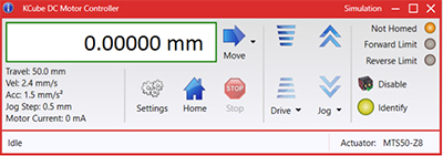
Figure 58A Kinesis GUI Screen
Thorlabs offers the Kinesis® software package to drive our wide range of motion controllers. The software can be used to control devices in the Kinesis family, which covers a wide variety of motion controllers ranging from small, low-powered, single-channel drivers (such as the K-Cubes®) to high-power, multi-channel benchtop units and modular 19" rack nanopositioning systems (the MMR60x Rack System).
The Kinesis Software features .NET controls which can be used by 3rd party developers working in the latest C#, Visual Basic, LabVIEW™, or any .NET compatible languages to create custom applications. Low-level DLL libraries are included for applications not expected to use the .NET framework and APIs are included with each install. A Central Sequence Manager supports integration and synchronization of all Thorlabs motion control hardware.
By providing this common software platform, Thorlabs has ensured that users can mix and match any of our motion control devices in a single application, while only having to learn a single set of software tools. In this way, it is perfectly feasible to combine any of the controllers from single-axis to multi-axis systems and control all from a single, PC-based unified software interface.
The software package allows two methods of usage: graphical user interface (GUI) utilities for direct interaction with and control of the controllers 'out of the box', and a set of programming interfaces that allow custom-integrated positioning and alignment solutions to be easily programmed in the development language of choice.
Reading a Vernier Scale on a Linear Main Scale
Vernier scales are typically used to add precision to standard, evenly divided scales (such as the scales on Thorlabs' rotation, goniometric, or translation mounts). A vernier scale has found common use in many precision measurement instruments, the most common being calipers and micrometers. The vernier scale uses two scales side-by-side: the main scale and the vernier scale. The direct vernier scale has a slightly smaller spacing between its tick marks owing to the vernier scale having N ticks for every N - 1 ticks on the main scale. Hence, the lines on the main scale will not line up with all the lines on the vernier scale. Only one line from the vernier scale will match well with one line of the main scale, and that is the trick to reading a vernier scale.
Figures 130A through 130C show a linear vernier scale system for three different situations. In each case, the scale on the left is the main scale, while the small scale on the right is the vernier scale. When reading a vernier scale, the main scale is used for the gross number, and the vernier scale gives the precision value. In this manner, a standard ruler or micrometer can become a precision instrument.
The 0 on the vernier scale is the "pointer" (marked by a red arrow in Figures 130A through 130E) and will indicate the main scale reading. In Figure 130A we see the pointer is lined up directly with the 75.6 line. Notice that the only other vernier scale tick mark that lines up well with the main scale is 10. Since the pointer lines up with the main scale’s 75.6, the reading from Figure 130A is 75.60 (in whatever units the instrument measures).
That is essentially all there is to reading a vernier scale. It's a very straightforward way of increasing the precision of a measurement instrument. To expound, let’s look at Figure 130B. Here we see that the pointer is no longer aligned with a line on the main scale, but instead it is slightly above 75.6 and below 75.7; thus, the gross measurement is 75.6. The first vernier line that coincides with a main scale line is the 5, shown with a blue arrow. The vernier scale gives the final digit of precision; since the 5 is aligned to the main scale, the precision measurement for Figure 130B is 75.65.
Since this vernier scale is 10% smaller than the main scale, moving the vernier scale by 1/10 of the main scale will align the next vernier marking. This asks the obvious question: what if the measurement is within the 1/10 precision of the vernier scale? Figure 130C shows just this. Again, the pointer line is in between 75.6 and 75.7, yielding the gross measurement of 75.6. If we look closely, we see that the vernier scale 7 (marked with a blue arrow) is very closely aligned to the main scale, giving a precision measurement of 75.67. However, the vernier scale 7 is very slightly above the main scale mark, and we can see that the vernier scale 8 (directly above 7) is slightly below its corresponding main scale mark. Hence, the scale on Figure 130C could be read as 75.673 ± 0.002. A reading error of about 0.002 would be appropriate for
this instrument.
Click to Enlarge
Figure 130A An example of how to read a vernier scale. The red arrow indicates what is known as the pointer. Since the tick mark labeled 10 on the vernier scale aligns with one of the tick marks on the main scale, this vernier scale is reading 75.60 (in whatever units the instrument measures).
Click to Enlarge
Figure 130B The red arrow indicates the pointer and the blue arrow indicates the vernier line that matches the main scale. This scale reads 75.65.
Click to Enlarge
Figure 130C The red arrow indicates the pointer, and the blue arrow indicates the vernier line that matches the main scale. This scale reads 75.67 but can be accurately read as
75.673 ± 0.002.
Reading a Vernier Scale on a Rotating Main Scale
The vernier scale may also be used on rotating scales where the main scale and vernier scale do not share units. Figures 130D and 130F show a vernier scale system for two different situations where the main scale is given in degrees and the vernier scale has ticks every 5 arcmin (60 arcmin = 1°). In each case, the scale on the top is the main scale, while the small scale on the bottom is the vernier scale.
In Figure 130D we see the pointer is lined up directly with the 341° line. Notice that the only other vernier scale tick marks that line up well with the main scale are ±60 arcmin. Since the pointer lines up with the main scale at 341°, the reading from Figure 130D is 341.00°.
There are two ways to determine the reading if the zero on the vernier scale line is between two lines of the main scale. For the first method, take the line on the left side of the pointer on the vernier scale and subtract that value (in arcmin) from the value on the main scale that is to the right on the main scale. As an example, in Figure 130E the vernier pointer is between 342° and 343°; using the left blue arrow of the vernier scale results in
As we've seen here, vernier scales add precision to a standard scale measurement. While it takes a bit of getting used to, with a little practice, reading these scales is fairly straightforward. Vernier scales, whether they are direct or retrograde*, are read in the same fashion.
*A retrograde vernier scale has a larger spacing between its tick marks with N ticks for every N + 1 ticks on the main scale.
Click to Enlarge
Figure 130D An example of a vernier scale where the main scale and the vernier scale are in different units (degrees and arcmins, respectively). The red arrow indicates the pointer. This scale reads 341.00°.
Click to Enlarge
Figure 130E The red arrow indicates the pointer and the blue arrows give the precision value from the vernier scale.
This scale reads 342.75°.
| Posted Comments: | |
Liam McRae
(posted 2025-03-05 14:18:24.44) I just wanted to inquire whether there was any motorized option that could extend to +- 12 degree, what could be achieved on the GN05 for instance. Or just some means to extend even the GNL10 to +-10 degree jdelia
(posted 2025-03-07 01:12:23.0) Thank you for contacting Thorlabs. At this time, we unfortunately do not offer a motorized goniometer option with this high of an angular range. I have reached out to you directly to discuss your application. Kaia Williams
(posted 2025-01-03 18:17:31.7) It would be really helpful if you could list out the nominal scaling between the linear motion commanded by the motorized stage and the resultant angular displacement of the goniometer stage. cdolbashian
(posted 2025-01-23 04:23:47.0) Thank you for reaching out to us with this inquiry. For the motorized units, you should be able to select a goniometer-associated linear actuator within the kinesis software which will display units of degrees rather than linear displacement (mm). This was the case with previously released linear actuators, though it seems like it was not implemented for the most recent actuator release. We are working on re-implementing it currently. Olivier Schalm
(posted 2023-12-22 09:08:36.25) Hello,
I would like to build a setup where a goniometer rocks continuously for a long period in a controlled way to test the reliability of an orientation sensor and how its calibration drifts over time.
Question 1: is the rotating motor automatically transmitted into a rocking motion of the stage (and can I chang the speed) or does the motor rotate forward and backward consecutively?
Question 2: Do I need the K-Cube™ DC Servo Motor Controller to perform this motion? ksosnowski
(posted 2023-12-22 10:12:48.0) Hello Olivier, thanks for reaching out to Thorlabs. The linear motor in these stages pushes the moving world towards one end of travel, while a return spring will pull the moving world back against the tip of the motor while it retracts. Since the tip of the motor provides linear motion, there would need to be commands for each position to be hit. The Kinesis software has a built in Sequencer that would allow you to configure this type of repetitive motion. Since these versions of the goniometer have our Z8 (soon to be Z9) series DC motors they will each require one KDC101 per axis to operate. I have reached out directly to discuss this further. user
(posted 2023-08-22 14:16:26.143) Please advise a better way to the actuator move count -->
deg translation. It is silly that i have to move it then read how much the goniometer translates .... cdolbashian
(posted 2023-08-30 09:52:46.0) Thank you for your suggestion! As this is not a feature which we currently have, I think a good solution for now would be to create a lookup table for your operation, which would correlate angular motion to linear actuation. If you are implementing this within a 3rd party software, all of the conversion could be calculated in the background, and you would be able to interface directly with the units of degrees. I have contacted you directly to discuss this further! 浪 陈
(posted 2022-08-04 19:48:10.137) 请问除了旋转角度的功能之外,能不能当成电动位移平台使用 cdolbashian
(posted 2022-08-18 03:11:18.0) Thank you for reaching out to us! Your question was "In addition to the rotation function, can it be used as a motorized translation stage?"
While these devices use similar actuators as our translation stages, they are designed only for the "rotation" function. They can be combined with a translation stage to achieve more degrees of freedom though. Tan De
(posted 2021-03-10 16:05:25.223) Hi,
for the GNL10-Z8(/M) it is stated that the accuracy is 10 arc minutes. How many mm does this correspond to on the Kinesis software?
Regards,
Wei De asundararaj
(posted 2021-03-29 02:59:08.0) Thank you for contacting Thorlabs. The arcmin precision is obtained using the vernier scale on the side of the mount, I have contacted you directly with additional information on this. user
(posted 2020-09-13 01:03:12.25) Hi,
following the prior comment written posted on 2020-09-07 05:51:11.08, what is the distance from the lower scales to the point of rotation ?
Thanks in advance llamb
(posted 2020-09-16 03:40:45.0) Thank you for contacting Thorlabs. After discussing further by email, the radius of curvature for each goniometer's top plate is being requested when referring to the distance between the point of rotation and the scales. For the GNL20-Z8, the radius of the top plate of the top goniometer (our GNL10) is 1.623". The radius for the top plate of the bottom goniometer (our GNL18) is 2.314". user
(posted 2020-09-07 05:51:11.08) Hi,
is it possible to detail the distance between the point of rotation to the upper\lower motors scales and not only the distance from the top plate to the rotation point?
I'd like to have an exact radius of the rotation.
Thanks YLohia
(posted 2020-09-11 10:22:29.0) Hello, thank you for contacting Thorlabs. For the GNL20-Z8, the distance between the scales and the surface of the top plate is 11.159 mm. This makes the total distance between the point of rotation and scales 25.4 mm (1") + 11.159 mm = 36.559 mm. user
(posted 2020-07-06 09:00:57.407) Hi,
is there any possiblitity to set a custom home position for the GNL10/M-Z8. It would be nice to position the gonimeter to the 0 Degree position and move it from there to the required position.
Thank you.
M. llamb
(posted 2020-07-20 04:03:12.0) Hello M, thank you for contacting Thorlabs. You can use our Motion Control Software to implement your own Zero Offset through the Settings menu in the software GUI. liu chi
(posted 2019-12-04 16:07:00.39) 现在我可以用GUI来控制角位移台的运动,但我想知道我可以用命令来控制这款角位移台的运动吗?如果可以的话,有没有简易指南之类的能否提供?不胜感激 llamb
(posted 2019-12-05 07:28:23.0) Thank you for contacting Thorlabs. Our APT or Kinesis Motion Control Software can indeed be implemented in third party software for using commands to control your stage. You can find some guides under the APT Tutorials tab on this page, as well as by navigating from this link: https://www.thorlabs.com/navigation.cfm?guide_id=2251. You may also reach out to techsupport-cn@thorlabs.com directly for future technical inquiries. We have reached out to you directly in this case to discuss how you would like to send commands to your stage.
感谢您与Thorlabs联系。 实际上,我们的APT或Kinesis运动控制软件可以在第三方软件中实现,以使用命令来控制舞台。 您可以在此页面的“ APT教程”标签下找到一些指南,也可以通过以下链接导航:https://www.thorlabs.com/navigation.cfm?guide_id=2251。 您也可以直接联系techsupport-cn@thorlabs.com,以进行将来的技术咨询。 在这种情况下,我们已经直接与您联系,讨论您希望如何将命令发送到舞台。 lingxu
(posted 2016-02-10 14:38:56.31) The tilt value displayed in APT cannot be converted to rotation in radians, therefore I could not use this stage to set the tilt to a specific value. besembeson
(posted 2016-03-03 10:03:40.0) Response from Bweh at Thorlabs USA: The actuator is not calibrated with respect to the goniometer stage when we ship these systems. You will have to perform such a calibration to relate the goniometer tilt with the actuator position. I will follow-up with you to further discuss this. scott.gagnon
(posted 2014-03-18 15:59:25.32) You should list the operating temps with your spec sheets. myanakas
(posted 2014-03-19 12:40:04.0) Thank you for you feedback. Currently the operating temperature is in the specifications section of the linked manual and the "Specs" tab. The manual can be found by clicking on the red "Docs" icon next to the part numbers. |

 Zoom
Zoom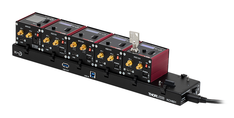 Click to Enlarge
KCH601 USB Controller Hub (Sold Separately) with Installed K-Cube® Modules
- Front Panel Velocity Wheel and Digital Display for Controlling Motorized Stages or Actuators
- Two Bidirectional Trigger Ports to Read or Control External Equipment
- Interfaces with Computer Using Included USB Cable
- Fully Compatible with Kinesis Software Package
- Compact Footprint: 60.0 mm x 60.0 mm x 49.2 mm (2.42" x 2.42" x 1.94")
- Power Supply Not Included (See Below)
Thorlabs' KDC101 K-Cube® Brushed DC Motor Controller provides local and computerized control of a single motor axis. It features a top-mounted control panel with a velocity wheel that supports four-speed bidirectional control with forward and reverse jogging as well as position presets. A backlit digital display is also included that can have the backlit dimmed or turned off using the top-panel menu options. The front of the unit contains two bidirectional trigger ports that can be used to read a 5 V external logic signal or output a 5 V logic signal to control external equipment. Each port can be independently configured.
The unit is fully compatible with our Kinesis software package. Please note that while the KDC101 controller is also fully supported by our XA software suite, the GNL series goniometers are not supported at this time, so the Kinesis software package should be used. A full list of products supported by XA can be found here. Please see the Kinesis Software tab for more information.
Please note that this controller does not ship with a power supply. Compatible power supplies are listed below. Additional information can be found on the main KDC101 DC Servo Motor Controller page.

 Zoom
Zoom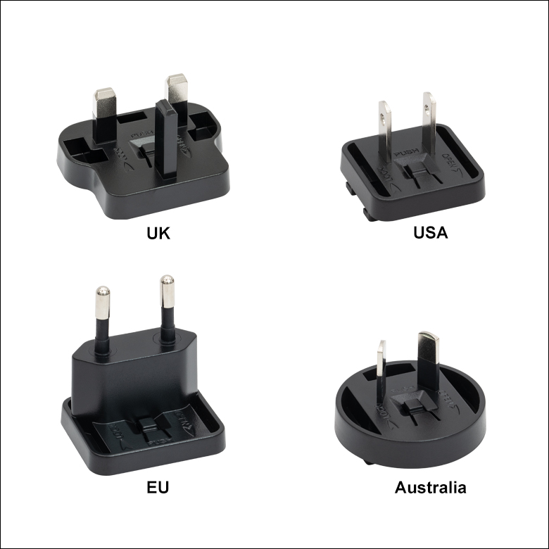
Click for Details
Figure 780B Each KPS201 power supply includes one region-specific adapter, which can be selected upon checkout.
Click to Enlarge
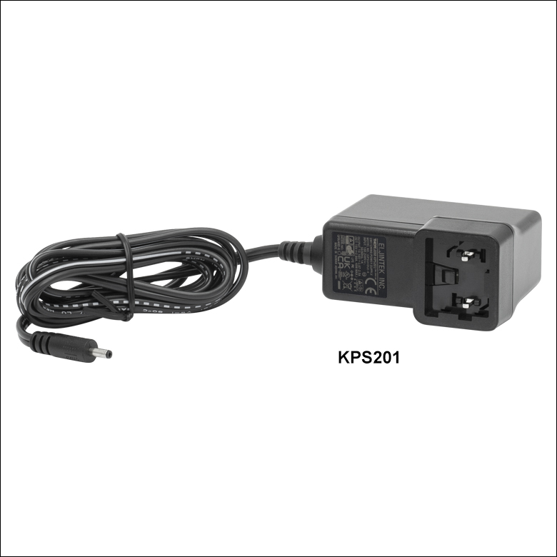
Figure 780A The KPS201 Power Supply Unit
- Individual Power Supply
- KPS201: For K-Cubes® or T-Cubes™ with 3.5 mm Jacks
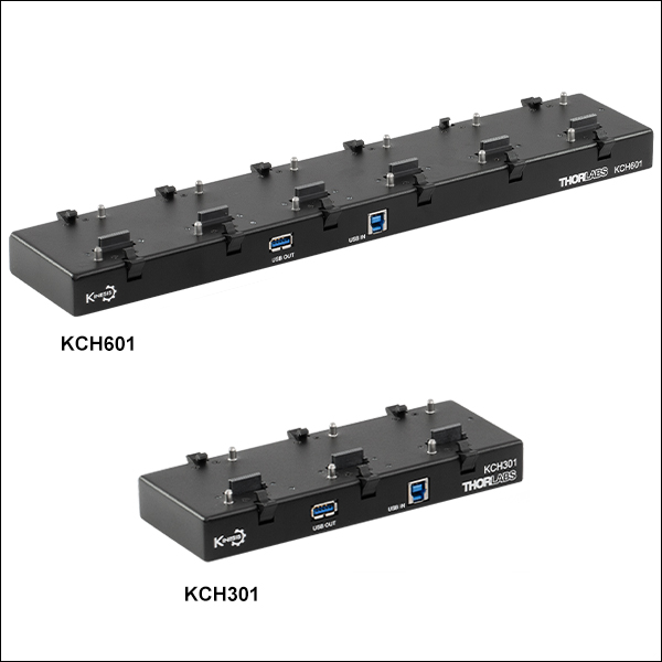
- USB Controller Hubs Provide Power and Communications
- KCH301: For Up to Three K-Cubes or T-Cubes
- KCH601: For Up to Six K-Cubes or T-Cubes
The KPS201 power supply outputs +15 VDC at up to 2.66 A and can power a single K-Cube or T-Cube with a 3.5 mm jack. It plugs into a standard wall outlet.
The KCH301 and KCH601 USB Controller Hubs each consist of two parts: the hub, which can support up to three (KCH301) or six (KCH601) K-Cubes or T-Cubes, and a power supply that plugs into a standard wall outlet. The hub draws a maximum current of 10 A; please verify that the cubes being used do not require a total current of more than 10 A. In addition, the hub provides USB connectivity to any docked K-Cube or T-Cube through a single USB connection.
For more information on the USB Controller Hubs, see the full web presentation.