 Products Home / Imaging Systems / OCT Imaging Systems & Components / OCT Components / Superluminescent Diode (SLD) Light Sources for OCT Systems
Superluminescent Diode (SLD) Light Sources for OCT Systems
- SLDs Optimized for Use in OCT Systems
- Center Wavelengths from 770 nm to 1610 nm
- Fiber-Coupled Power: ≥3 mW
- SM or PM Fiber Pigtail with FC/APC Connector
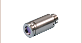
SLD1325
1325 nm SLD, >100 nm Bandwidth
30 dB (Min) Optical Isolation
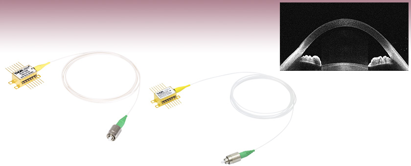
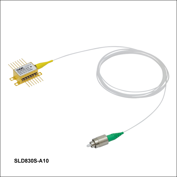
An Image of the Anterior of the Eye Taken with the SLD830S-A10 in a Modified Ganymede ll OCT System
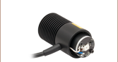
SLD830S-A10
830 nm SLD, Gain Ripple: ≤0.15 dB


Please Wait
Click to Enlarge
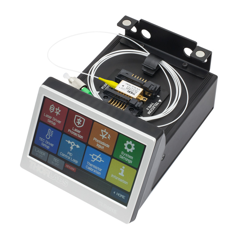
The SLD1325 Superluminescent Diode Mounted in a CLD1015 Compact Laser Diode Driver with TEC
Features
- SLDs Optimized for Use in Spectral Domain OCT Systems
- 770 nm to 1610 nm Center Wavelengths (See Quick Links Table to the Right)
- FC/APC-Terminated Fiber Pigtail Minimizes Optical Feedback
- Integrated TEC and Thermistor for Temperature Control
- Hermetically Sealed 14-Pin Butterfly Package
- 1315 nm, 1325 nm, and 1400 nm Center Wavelength (CWL) SLDs Available from Stock with Integrated Optical Isolator
Superluminescent Diodes (SLDs) are the light source of choice in Spectral Domain Optical Coherence Tomography (SD-OCT) imaging. The broad spectrum and short coherence length of the emitted light improve the depth resolution in OCT images. Thorlabs offers SLDs designed for OCT applications with center wavelengths from 770 nm to 1610 nm (see the Quick Links table to the right). Each SLD is shipped with an individualized product data sheet, which includes information on the spectrum and operating parameters of the device. Raw test data for each SLD is also available upon request; please contact Tech Support with inquiries. For more details about each SLD, please see the Specs tab.
These devices are built into 14-pin butterfly packages, each with an integrated thermoelectric cooler (TEC) and thermistor to ensure output stability. The output is coupled into either an SM or PM fiber terminated with a 2.0 mm narrow key FC/APC connector. Please note that optical feedback can diminish the output power or damage the SLD. We do not recommend using these SLDs with components that are prone to back reflections, such as FC/PC connectors. The SLD1310x, SLD1325, SLD1330x, and SLD1410x superluminescent diodes incorporate an integrated optical isolator. If you are interested in an SLD at a different wavelength with an integrated isolator, please contact Tech Support with inquiries.
Thorlabs is able to provide low-ripple SLDs with custom wavelengths or higher power diodes. Please note that the engineering design and wafer manufacturing costs involved make the purchase of low quantities very costly. For a quote on custom SLDs, please contact Tech Support.
The SLDs featured on this page have either a near-Gaussian or flat-top optical spectrum. The calculation for the center wavelength differs with these two spectral shapes. Please see the Specs tab for center wavelength calculations.
For additional wavelengths and devices not optimized for OCT, see our full selection of superluminescent diodes.
Operation Guidelines
We strongly recommend adherence to the operating conditions marked on each package. While optimal performance is achieved by utilizing the recommended settings, we recognize users can adjust the spectral characteristics of the SLD by deviating from these recommended settings. For instance, operating at lower temperatures will cause a shift of the central wavelength to shorter wavelengths. It is imperative, however, that as the temperature is reduced, the injection current is also reduced so as not to exceed the recommended output power if one is noted on the data sheet that is included with the SLD.
These SLDs should be operated at a constant current and temperature, which is relatively simple with the proper SLD mount and drivers. To mount and drive these SLDs, Thorlabs recommends using a ITC4000 Series Laser Diode Driver with the LM14S2 Mount. For applications where lower noise is desirable, the CLD1015 Compact Laser Diode Driver with TEC is available as a standalone laser driver and temperature controller.
As with most active semiconductor devices, standard anti-static handling procedures must be adhered to in order to prevent an electrical discharge that could destroy the device.
OCT Application Images
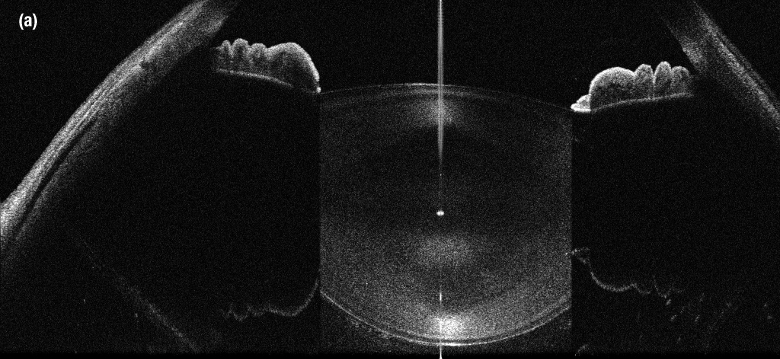
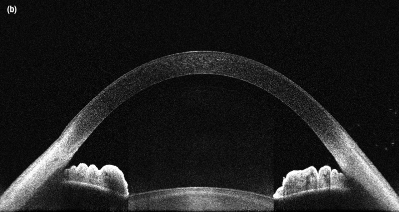
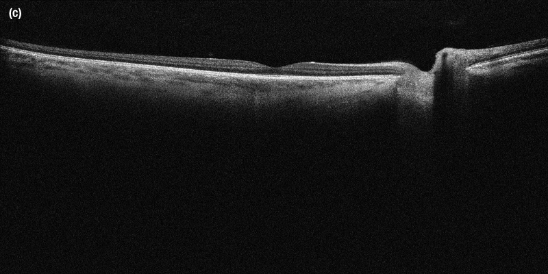
SLD830S-A10 (sold below) as a light source. The images each have an in-tissue depth of 6.2 mm and were taken using a 36 kHz A-scan rate.
Due to the nature of producing superluminescent diodes with ultra wide bandwidths, some of the SLDs sold below have spectral shapes that are near gaussian, while others have a shape with a flattened top. This difference in spectral shape demands two different methods of defining center wavelength in order to provide an accurate description of the diode.
Near-Guassian Center Wavelength Definition
The center wavelength for devices with a near-gaussian spectral shape is defined by an average weighted by the relative amplitude and may not correspond to peak power or the FWHM center wavelength due to the variability of the spectrum shape. For a given Optical Spectrum Analyzer (OSA) trace:
where
- CW is the Specified Center Wavelength
- Xi is the Wavelength of a Trace Data Point
- Yi is the Amplitude of a Trace Data Point
Flat-Top Center Wavelength Definition
The center wavelength for devices with a flat-top spectral shape is defined by the midpoint between the two wavelengths located at 3 dB below the maximum intensity point on the spectrum. For a given OSA trace:
where
- CW is the Specified Center Wavelength
- XR_3dB is the Right Wavelength Edge of the 3 dB Bandwidth
- XL_3dB is the Left Wavelength Edge of the 3 dB Bandwidth
SLD Specifications
Note that these specifications are given as guidelines. The characterization sheet shipped with each SLD provides the minimum, maximum, and recommended operating parameters and specifications specific to that device. Note: the ASE Power specification is the output from the fiber pigtail.
770 nm CWL Superluminescent Diode
| Item # | SLD770S | ||
|---|---|---|---|
| Parametera | Min | Typ. | Max |
| Center Wavelength (CWL)b | 760 nm | 770 nm | 780 nm |
| Spectral Shape | Near Gaussian | ||
| Operating Current | - | - | 170 mA |
| ASE Powerc | 4.5 mW | 5.5 mW | - |
| Optical 3 dB Bandwidthc,d | 15 nm | 18 nm | - |
| RMS Gain Ripplec | - | 0.01 dB | 0.3 dB |
| Forward Voltagec | - | 1.95 V | 2.5 V |
| TEC Operation: Typ. / Max @ TCASE = 25 °C / 70 °C | |||
| TEC Current | - | 0.11 A | 1.4 A |
| TEC Voltage | - | 0.16 V | 4.0 V |
| Thermistor Resistance | - | 10 kΩ | - |
| Performance Graphs (Click Icons for Plots) | |||
| Output Spectrum |  |
||
| LIV Plot |  |
||
| Gain Ripplec,e |  |
||
| Absolute Maximum Ratingsa | |||
| Absolute Max Current | 170 mA | ||
| Operating Case Temperature | 0 to 70 °C | ||
| Storage Temperature | -10 to 70 °C | ||
| Pin Code | 14 Pin, Type 1 | ||
| Fiber Specifications | |||
| Fiber Type | 780HP | ||
| Numerical Aperture | 0.13 | ||
| Core Diameter | 4.4 µm | ||
| Mode Field Diameter (Nominal) | 5.0 ± 0.5 µm @ 850 nm | ||
| Fiber Length | 1.5 m | ||
| Connector | FC/APC, 2.0 mm Narrow Key | ||
810 nm CWL Superluminescent Diode
| Item # | SLD810S | |||||
|---|---|---|---|---|---|---|
| Parametera | Min | Typical | Max | |||
| Center Wavelength (CWL)b | 795 nm | 810 nm | 825 nm | |||
| Spectral Shape | Near Gaussian | |||||
| Operating Current | - | - | 270 mA | |||
| ASE Powerc | 13 mW | 15 mW | - | |||
| Optical 3 dB Bandwidthc,d | 25 nm | 30 nm | - | |||
| RMS Gain Ripplec,e | - | 0.03 dB | 0.15 dB | |||
| Forward Voltage | - | 2.1 V | 2.5 V | |||
| TEC Operation: Typ. / Max @ TCASE = 25 °C / 70 °C | ||||||
| TEC Current | - | 0.2 A | 1.4 A | |||
| TEC Voltage | - | 0.3 V | 6.0 V | |||
| Thermistor Resistance | - | 10 kΩ | - | |||
| Performance Graphs (Click Icons for Plots) | ||||||
| Output Spectrum | ||||||
| LIV Plot | ||||||
| Gain Ripplec,e | ||||||
| Absolute Maximum Ratingsa | ||||||
| Absolute Max Current | 290 mA | |||||
| Operating Case Temperature | 0 to 70 °C | |||||
| Storage Temperature | -10 to 70 °C | |||||
| Pin Code | 14 Pin, Type 1 | |||||
| Fiber Specifications | ||||||
| Fiber Type | 780HP | |||||
| Numerical Aperture | 0.13 | |||||
| Core Diameter | 4.4 µm | |||||
| Mode Field Diameter (Nominal) | 5.0 ± 0.5 µm @ 850 nm | |||||
| Fiber Length | 1.5 m | |||||
| Connector | FC/APC, 2.0 mm Narrow Key | |||||
830 nm CWL Superluminescent Diodes
| Item # | SLD830S-A10W | SLD830S-A20W | SLD830S-A10 | SLD830S-A20 | ||||||||
|---|---|---|---|---|---|---|---|---|---|---|---|---|
| Parametera | Min | Typical | Max | Min | Typical | Max | Min | Typical | Max | Min | Typical | Max |
| Center Wavelength (CWL)b | 815 nm | 830 nm | 845 nm | 815 nm | 830 nm | 845 nm | 820 nm | 830 nm | 840 nm | 820 nm | 830 nm | 840 nm |
| Spectral Shape | Flat Top | Flat Top | Near Gaussian | Near Gaussian | ||||||||
| Operating Current | - | - | 240 mA | - | - | 330 mA | - | - | 150 mA | - | - | 240 mA |
| ASE Powerc,d | 10 mW | - | - | 20 mW | - | - | 10 mW | 13 mW | - | 20 mW | 22 mW | - |
| Optical 3 dB Bandwidthc,e | 50 nm | 60 nm | - | 40 nm | 55 nm | - | 17 nm | 20 nm | - | 17 nm | 20 nm | - |
| Optical 20 dB Bandwidthc | - | - | - | - | - | - | - | 50 nm | - | - | 50 nm | - |
| RMS Gain Ripplec,f | - | 0.06 dB | 0.3 dB | - | 0.03 dB | 0.3 dB | - | 0.03 dB | 0.15 dB | - | 0.03 dB | 0.15 dB |
| Forward Voltagec | - | 2.0 V | 2.5 V | - | 2.0 V | 2.5 V | - | 2.0 V | 2.5 V | - | 2.0 V | 2.5 V |
| TEC Operation: Typ. / Max @ TCASE = 25 °C / 70 °C | ||||||||||||
| TEC Current | - | 0.14 A | 1.4 A | - | 0.14 A | 1.4 A | - | 0.1 A | 1.5 A | - | 0.1 A | 1.5 A |
| TEC Voltage | - | 0.18 V | 6.0 V | - | 0.18 V | 6.0 V | - | 0.13 V | 4.0 V | - | 0.13 V | 4.0 V |
| Thermistor Resistance | - | 10 kΩ | - | - | 10 kΩ | - | - | 10 kΩ | - | - | 10 kΩ | - |
| Performance Graphs (Click Icons for Plots) | ||||||||||||
| Output Spectrum | ||||||||||||
| LIV Plot | ||||||||||||
| Gain Ripplef | ||||||||||||
| Absolute Maximum Ratingsa | ||||||||||||
| Absolute Max Current | 240 mA | 330 mA | 150 mA | 240 mA | ||||||||
| Operating Case Temperature | 0 to 70 °C | |||||||||||
| Storage Temperature | -10 to 70 °C | |||||||||||
| Pin Code | 14 Pin, Type 1 | |||||||||||
| Fiber Specifications | ||||||||||||
| Fiber Type | 780HP | |||||||||||
| Numerical Aperture | 0.13 | |||||||||||
| Core Diameter | 4.4 µm | |||||||||||
| Mode Field Diameter (Nominal) | 5.0 ± 0.5 µm @ 850 nm | |||||||||||
| Fiber Length | 1.5 m | |||||||||||
| Connector | FC/APC, 2.0 mm Narrow Key | |||||||||||
840 nm CWL Superluminescent Diodes
| Item # | SLD840 | SLD840P | ||||
|---|---|---|---|---|---|---|
| Parametera | Min | Typical | Max | Min | Typical | Max |
| Center Wavelength (CWL)b | 820 nm | 840 nm | 860 nm | 820 nm | 840 nm | 860 nm |
| Spectral Shape | Flat Top | Flat Top | ||||
| Operating Current | - | 140 mA | 180 mA | - | 140 mA | 180 mA |
| ASE Powerc,d | 3 mW | 4 mW | - | 3 mW | 4 mW | - |
| Optical 3 dB Bandwidthc,d,e | 60 nm | 70 nm | - | 60 nm | 70 nm | - |
| RMS Gain Ripplec,f | - | 0.01 dB | 0.1 dB | - | 0.01 dB | 0.1 dB |
| Forward Voltagec | - | 2.0 V | 2.5 V | - | 2.0 V | 2.5 V |
| Polarization Extinction Ratio (PER) | - | - | - | - | 16 dB | - |
| TEC Operation: Typ. / Max @ TCASE = 25 °C / 70 °C | ||||||
| TEC Current | - | 0.1 A | 1.5 A | - | 0.1 A | 1.5 A |
| TEC Voltage | - | 0.15 V | 4.0 V | - | 0.15 V | 4.0 V |
| Thermistor Resistance | - | 10 kΩ | - | - | 10 kΩ | - |
| Steinhart-Hart Coefficients | C1 = 1.1291x10⁻³, C2 = 2.3413x10⁻⁴, and C3 = 0.8767x10⁻⁷ | |||||
| Performance Graphs (Click Icons for Plots) | ||||||
| Output Spectrum | ||||||
| LIV Plot | ||||||
| Gain Ripplef | ||||||
| Absolute Maximum Ratingsg | ||||||
| Absolute Max Current | 180 mA | 180 mA | ||||
| Operating Case Temperature | 0 to 70 °C | 0 to 70 °C | ||||
| Storage Temperature | -10 to 70 °C | -10 to 70 °C | ||||
| Pin Code | 14 Pin, Type 1 | 14 Pin, Type 1 | ||||
| Fiber Specifications | ||||||
| Fiber Type | 780HP | PM780-HPh | ||||
| Numerical Aperture | 0.13 | 0.12 | ||||
| Core Diameter | 4.4 µm | 4.5 µm | ||||
| Mode Field Diameter (Nominal) | 5.0 ± 0.5 µm @ 850 nm | 5.3 ± 1.0 µm @ 850 nm | ||||
| Fiber Length | 1.5 m | 1.5 m | ||||
| Connector | FC/APC, 2.0 mm Narrow Key | FC/APC, 2.0 mm Narrow Key | ||||
850 nm CWL Superluminescent Diodes
| Item # | SLD850S-A10W | SLD850S-A20W | ||||
|---|---|---|---|---|---|---|
| Parametera | Min | Typical | Max | Min | Typical | Max |
| Center Wavelength (CWL)b | 835 nm | 850 nm | 865 nm | 835 nm | 850 nm | 865 nm |
| Spectral Shape | Flat Top | Flat Top | ||||
| Operating Current | - | - | 180 mA | - | - | 340 mA |
| ASE Powerc,d | 10 mW | - | - | 20 mW | - | - |
| Optical 3 dB Bandwidthc,d | 40 nm | 60 nm | - | 40 nm | 55 nm | - |
| RMS Gain Ripplec,e | - | 0.03 dB | 0.3 dB | - | 0.03 dB | 0.3 dB |
| Forward Voltagec | - | 2.0 V | 2.5 V | - | 2.0 V | 2.5 V |
| TEC Operation: Typ. / Max @ TCASE = 25 °C / 70 °C | ||||||
| TEC Current | - | 0.11 A | 1.4 A | - | 0.18 A | 1.4 A |
| TEC Voltage | - | 0.17 V | 6.0 V | - | 0.27 V | 6.0 V |
| Thermistor Resistance | - | 10 kΩ | - | - | 10 kΩ | - |
| Performance Graphs (Click Icons for Plots) | ||||||
| Output Spectrum | ||||||
| LIV Plot | ||||||
| Gain Ripplee | ||||||
| Absolute Maximum Ratingsa | ||||||
| Absolute Max Current | 180 mA | 340 mA | ||||
| Operating Case Temperature | 0 to 70 °C | |||||
| Storage Temperature | -10 to 70 °C | |||||
| Pin Code | 14 Pin, Type 1 | |||||
| Fiber Specifications | ||||||
| Fiber Type | 780HP | |||||
| Numerical Aperture | 0.13 | |||||
| Core Diameter | 4.4 µm | |||||
| Mode Field Diameter (Nominal) | 5.0 ± 0.5 µm @ 850 nm | |||||
| Fiber Length | 1.5 m | |||||
| Connector | FC/APC, 2.0 mm Narrow Key | |||||
880 nm CWL Superluminescent Diodes
| Item # | SLD880S-A7 | SLD880S-A25 | ||||
|---|---|---|---|---|---|---|
| Parametera | Min | Typical | Max | Min | Typical | Max |
| Center Wavelength (CWL)b | 860 nm | 880 nm | 900 nm | 860 nm | 880 nm | 900 nm |
| Spectral Shape | Flat Top | Flat Top | ||||
| Operating Current | - | - | 225 mA | - | - | 410 mA |
| ASE Powerc,d | 6 mW | 7 mW | - | 23 mW | 25 mW | - |
| Optical 3 dB Bandwidthc | 35 nm | 40 nm | - | 35 nm | 40 nm | - |
| Optical 20 dB Bandwidthc | - | 80 nm | - | - | 80 nm | - |
| RMS Gain Ripplec,e | - | 0.06 dB | 0.3 dB | - | 0.06 dB | 0.3 dB |
| Forward Voltagec | - | 2.0 V | 2.5 V | - | 2.0 V | 2.5 V |
| TEC Operation: Typ. / Max @ TCASE = 25 °C / 70 °C | ||||||
| TEC Current | - | 0.2 A | 1.4 A | - | 0.2 A | 1.4 A |
| TEC Voltage | - | 0.8 V | 6.0 V | - | 0.8 V | 6.0 V |
| Thermistor Resistance | - | 10 kΩ | - | - | 10 kΩ | - |
| Performance Graphs (Click Icons for Plots) | ||||||
| Output Spectrum | ||||||
| LIV Plot | ||||||
| Gain Ripplee | ||||||
| Absolute Maximum Ratingsa | ||||||
| Absolute Max Current | 225 mA | 410 mA | ||||
| Operating Case Temperature | 0 to 70 °C | |||||
| Storage Temperature | -10 to 70 °C | |||||
| Pin Code | 14 Pin, Type 1 | |||||
| Fiber Specifications | ||||||
| Fiber Type | 780HP | |||||
| Numerical Aperture | 0.13 | |||||
| Core Diameter | 4.4 µm | |||||
| Mode Field Diameter (Nominal) | 5.0 ± 0.5 µm @ 850 nm | |||||
| Fiber Length | 1.0 ± 0.05 m | 1.5 ± 0.05 m | ||||
| Connector | FC/APC, 2.0 mm Narrow Key | |||||
920 nm CWL Superluminescent Diodes
| Item # | SLD920S | SLD920P | ||||
|---|---|---|---|---|---|---|
| Parametera | Min | Typical | Max | Min | Typical | Max |
| Operating Current | - | - | 420 mA | - | - | 420 mA |
| Center Wavelength (CWL)b | 895 nm | 920 nm | 945 nm | 895 nm | 920 nm | 945 nm |
| Spectral Shape | Flat Top | Flat Top | ||||
| ASE Powerc,d | 10 mW | 15 mW | - | 10 mW | 15 mW | - |
| Optical 3 dB Bandwidthc,d | 50 nm | 65 nm | - | 50 nm | 65 nm | - |
| RMS Gain Ripplec,e | - | 0.02 dB | 0.3 dB | - | 0.02 dB | 0.3 dB |
| Forward Voltagec | - | 2.0 V | 2.5 V | - | 2.0 V | 2.5 V |
| TEC Operation: Typ. / Max @ TCASE = 25 °C / 70 °C | ||||||
| TEC Current | - | 0.3 A | 1.4 A | - | 0.3 A | 1.4 A |
| TEC Voltage | - | 0.4 V | 6.0 V | - | 0.4 V | 6.0 V |
| Thermistor Resistance | - | 10 kΩ | - | - | 10 kΩ | - |
| Performance Graphs (Click Icons for Plots) | ||||||
| Output Spectrum | ||||||
| LIV Plot | ||||||
| Gain Ripplee | ||||||
| Absolute Maximum Ratingsa | ||||||
| Absolute Max Current | 420 mA | 420 mA | ||||
| Operating Case Temperature | 0 °C to 70 °C | 0 °C to 70 °C | ||||
| Storage Temperature | -10 °C to 70 °C | -10 °C to 70 °C | ||||
| Pin Code | 14 Pin, Type 1 | 14 Pin, Type 1 | ||||
| Fiber Specifications | ||||||
| Fiber Type | 780HP | PM780-HPf | ||||
| Numerical Aperture | 0.13 | 0.12 | ||||
| Core Diameter | 4.4 µm | 4.5 µm | ||||
| Mode Field Diameter (Nominal) | 5.0 ± 0.5 µm @ 850 nm | 5.3 ± 1.0 µm @ 850 nm | ||||
| Fiber Length | 1.5 m | 1.5 m | ||||
| Connector | FC/APC, 2.0 mm Narrow Key | FC/APC, 2.0 mm Narrow Key | ||||
930 nm CWL Superluminescent Diodes
| Item # | SLD930S-A40W | SLD930P-A40W | ||||
|---|---|---|---|---|---|---|
| Parametera | Min | Typical | Max | Min | Typical | Max |
| Operating Current | - | - | 800 mA | - | - | 800 mA |
| Center Wavelength (CWL)b | 915 nm | 930 nm | 945 nm | 915 nm | 930 nm | 945 nm |
| Spectral Shape | Flat Top | Flat Top | ||||
| ASE Powerc,d | 36 mW | 40 mW | - | 36 mW | 40 mW | - |
| Optical 3 dB Bandwidthc,d | 40 nm | 45 nm | - | 40 nm | 45 nm | - |
| RMS Gain Ripplec,e | - | 0.06 dB | 0.3 dB | - | 0.06 dB | 0.3 dB |
| Forward Voltagec | - | 2.0 V | 2.5 V | - | 2.0 V | 2.5 V |
| TEC Operation: Typ. / Max @ TCASE = 25 °C / 70 °C | ||||||
| TEC Current | - | 0.54 A | 1.4 A | - | 0.54 A | 1.4 A |
| TEC Voltage | - | 0.78 V | 6.0 V | - | 0.78 V | 6.0 V |
| Thermistor Resistance | - | 10 kΩ | - | - | 10 kΩ | - |
| Performance Graphs (Click Icons for Plots) | ||||||
| Output Spectrum | ||||||
| LIV Plot | ||||||
| Gain Ripplee | ||||||
| Absolute Maximum Ratingsa | ||||||
| Absolute Max Current | 800 mA | 800 mA | ||||
| Operating Case Temperature | 0 °C to 70 °C | 0 °C to 70 °C | ||||
| Storage Temperature | -10 °C to 70 °C | -10 °C to 70 °C | ||||
| Pin Code | 14 Pin, Type 1 | 14 Pin, Type 1 | ||||
| Fiber Specifications | ||||||
| Fiber Type | 780HP | PM780-HPf | ||||
| Numerical Aperture | 0.13 | 0.12 | ||||
| Core Diameter | 4.4 µm | 4.5 µm | ||||
| Mode Field Diameter (Nominal) | 5.0 ± 0.5 µm @ 850 nm | 5.3 ± 1.0 µm @ 850 nm | ||||
| Fiber Length | 1.5 m | 1.5 m | ||||
| Connector | FC/APC, 2.0 mm Narrow Key | FC/APC, 2.0 mm Narrow Key | ||||
970 nm CWL Superluminescent Diodes
| Item # | SLD970S-A40W | SLD970P-A40W | ||||
|---|---|---|---|---|---|---|
| Parametera | Min | Typical | Max | Min | Typical | Max |
| Operating Current | - | 1000 mA | 1010 mA | - | 1000 mA | 1010 mA |
| Center Wavelength (CWL)b | 945 nm | 970 nm | 995 nm | 945 nm | 970 nm | 995 nm |
| Spectral Shape | Flat Top | Flat Top | ||||
| ASE Powerc,d | 35 mW | 40 mW | - | 35 mW | 40 mW | - |
| Optical 3 dB Bandwidthc,d | 40 nm | 50 nm | - | 40 nm | 50 nm | - |
| RMS Gain Ripplec,e | - | 0.03 dB | 0.2 dB | - | 0.03 dB | 0.2 dB |
| Forward Voltagec | - | 2.0 V | 2.5 V | - | 2.0 V | 2.5 V |
| TEC Operation: Typ. / Max @ TCASE = 25 °C / 70 °C | ||||||
| TEC Current | - | 0.83 A | 1.4 A | - | 0.83 A | 1.4 A |
| TEC Voltage | - | 1.2 V | 6.0 V | - | 1.2 V | 6.0 V |
| Thermistor Resistance | - | 10 kΩ | - | - | 10 kΩ | - |
| Performance Graphs (Click Icons for Plots) | ||||||
| Output Spectrum | ||||||
| LIV Plot | ||||||
| Gain Ripplee | ||||||
| Absolute Maximum Ratingsa | ||||||
| Absolute Max Current | 1010 mA | 1010 mA | ||||
| Operating Case Temperature | 0 °C to 70 °C | 0 °C to 70 °C | ||||
| Storage Temperature | -10 °C to 70 °C | -10 °C to 70 °C | ||||
| Pin Code | 14 Pin, Type 1 | 14 Pin, Type 1 | ||||
| Fiber Specifications | ||||||
| Fiber Type | HI1060 | PM980-XPf | ||||
| Numerical Aperture | 0.14 | 0.12 | ||||
| Core Diameter | 5.8 µm | 5.5 µm | ||||
| Mode Field Diameter (Nominal) | 5.9 ± 0.3 µm @ 980 nm | 6.6 ± 0.5 µm @ 980 nm | ||||
| Fiber Length | 1.5 m | 1.5 m | ||||
| Connector | FC/APC, 2.0 mm Narrow Key | FC/APC, 2.0 mm Narrow Key | ||||
1050 nm CWL Superluminescent Diodes
| Item # | SLD1050S-A60a | SLD1050P-A60a | ||||
|---|---|---|---|---|---|---|
| Parametera | Min | Typical | Max | Min | Typical | Max |
| Center Wavelength (CWL)b | 1025 nm | 1050 nm | 1075 nm | 1025 nm | 1050 nm | 1075 nm |
| Spectral Shape | Flat Top | Flat Top | ||||
| Operating Current | - | - | 1010 mA | - | - | 1010 mA |
| ASE Powerc,d | 55 mW | 60 mW | - | 55 mW | 60 mW | - |
| Optical 3 dB Bandwidthc | 60 nm | 70 nm | - | 60 nm | 70 nm | - |
| Optical 20 dB Bandwidthc | - | 100 nm | - | - | - | - |
| RMS Gain Ripplec,e | - | 0.03 dB | 0.2 dB | - | 0.06 dB | 0.2 dB |
| Forward Voltagec | - | 2.0 V | 2.5 V | - | 2.0 V | 2.5 V |
| TEC Operation: Typ. / Max @ TCASE = 25 °C / 65 °C | ||||||
| TEC Current | - | 0.7 A | 2.5 A | - | 0.7 A | 2.5 A |
| TEC Voltage | - | 0.9 V | 3.2 V | - | 0.9 V | 3.2 V |
| Thermistor Resistance | - | 10 kΩ | - | - | 10 kΩ | - |
| Performance Graphs (Click Icons for Plots) | ||||||
| Output Spectrum | ||||||
| LIV Plot | ||||||
| Gain Ripplee | ||||||
| Absolute Maximum Ratingsa | ||||||
| Absolute Max Current | 1010 mA | 1010 mA | ||||
| Operating Case Temperature | 0 to 70 °C | 0 to 70 °C | ||||
| Storage Temperature | -10 to 70 °C | -10 to 70 °C | ||||
| Pin Code | 14 Pin, Type 1 | 14 Pin, Type 1 | ||||
| Fiber Specifications | ||||||
| Fiber Type | HI1060 | PM980-XPf | ||||
| Numerical Aperture | 0.14 | 0.12 | ||||
| Core Diameter | 6.2 µm | 5.5 µm | ||||
| Mode Field Diameter (Nominal) | 6.2 ± 0.3 µm @ 1060 nm | 6.6 ± 0.5 µm @ 980 nm | ||||
| Fiber Length | 1.5 m | 1.5 m | ||||
| Connector | FC/APC, 2.0 mm Narrow Key | FC/APC, 2.0 mm Narrow Key | ||||
1310 nm and 1315 nm CWL Superluminescent Diodes
| Item # | SLD1021S | SLD1310 | SLD1310P | ||||||
|---|---|---|---|---|---|---|---|---|---|
| Parametera | Min | Typical | Max | Min | Typical | Max | Min | Typical | Max |
| Operating Current | - | 700 mA | 900 mA | - | 900 mA | 1000 mA | - | 900 mA | 1000 mA |
| Center Wavelength (CWL)b | 1290 nm | - | 1330 nm | 1300 nm | 1315 nm | 1330 nm | 1300 nm | 1315 nm | 1330 nm |
| Spectral Shape | Near Gaussian | Flat Top | Flat Top | ||||||
| ASE Powerc,d | 10 mW | 12.5 mW | - | 22 mW | 30 mW | - | 22 mW | 30 mW | - |
| Optical 3 dB Bandwidthc,d,e | 80 nm | 85 nm | - | 75 nm | 90 nm | - | 75 nm | 90 nm | - |
| RMS Gain Ripplec,f | - | - | 0.35 dB | - | 0.12 dB | 0.3 dB | - | 0.12 dB | 0.3 dB |
| Forward Voltage | - | 1.55 V | 2.0 V | - | 2.0 V | 2.3 V | - | 2.0 V | 2.3 V |
| Polarization Extinction Ratio (PER) | - | - | - | - | - | - | - | 23 dB | - |
| Operating Temperature Range | 0 to 40 °C | 0 °C to 70 °C | 0 °C to 70 °C | ||||||
| TEC Operationg | |||||||||
| TEC Current | - | 0.4 A | 1.5 A | - | 0.7 A | 1.5 A | - | 0.7 A | 1.5 A |
| TEC Voltage | - | 0.5 V | 4 V | - | 1.0 V | 4.0 V | - | 1.0 V | 4.0 V |
| Thermistor Resistance | - | 10 kΩ | - | - | 10 kΩ | - | - | 10 kΩ | - |
| Integrated Isolator | |||||||||
| Isolation | N/Ah | - | 50 dB | - | - | 50 dB | - | ||
| Performance Graphs (Click Icons for Plots) | |||||||||
| Output Spectrum | |||||||||
| LIV Plot | |||||||||
| Gain Ripplef | - | ||||||||
| Absolute Maximum Ratingsi | |||||||||
| Absolute Max Current | - | - | 1000 mA | ||||||
| Operating Case Temperature | - | - | 0 °C to 70 °C | ||||||
| Storage Temperature | - | - | -10 °C to 70 °C | ||||||
| Pin Code | 14 Pin, Type 1 | 14 Pin, Type 1 | 14 Pin, Type 1 | ||||||
| Fiber Specifications | |||||||||
| Fiber Type | SMF-28+ | SMF-28e | Corning® PM13-U40Aj | ||||||
| Numerical Aperture | 0.14 | 0.14 | 0.12 | ||||||
| Core Diameter | 8.2 µm | 8.2 µm | - | ||||||
| Mode Field Diameter | 9.2 ± 0.4 µm @ 1310 nm 10.2 ± 0.5 µm @ 1550 nm |
9.2 ± 0.4 µm @ 1310 nm 10.2 ± 0.5 µm @ 1550 nm |
9.3 ± 0.5 µm @ 1300 nm | ||||||
| Fiber Length | 1.5 m | 1.5 m ± 0.05 m | 1.5 m ± 0.05 m | ||||||
| Connector | FC/APC, 2.0 mm Narrow Key | FC/APC, 2.0 mm Narrow Key | FC/APC, 2.0 mm Narrow Key | ||||||
1325 nm CWL Superluminescent Diodes
| Item # | SLD1325 | SLD1330 | SLD1330P | ||||||
|---|---|---|---|---|---|---|---|---|---|
| Parametera | Min | Typical | Max | Min | Typical | Max | Min | Typical | Max |
| Operating Current | - | - | 780 mA | - | 1250 mA | 1300 mA | - | 1250 mA | 1300 mA |
| Center Wavelength (CWL)b | - | 1325 nm | - | 1310 nm | 1325 nm | 1340 nm | 1310 nm | 1325 nm | 1340 nm |
| Spectral Shape | Flat Top | Flat Top | Flat Top | ||||||
| ASE Powerc,d | 10 mW | - | - | 35 mW | 40 mW | - | 35 mW | 40 mW | - |
| Optical 3 dB Bandwidthc,d,e | 100 nm | - | - | 80 nm | 90 nm | - | 80 nm | 90 nm | - |
| RMS Gain Ripplec,f | - | - | - | - | 0.1 dB | 0.3 dB | - | 0.1 dB | 0.3 dB |
| Forward Voltage | - | - | 4 V | - | 2.3 V | 2.5 V | - | 2.3 V | 2.5 V |
| Polarization Extinction Ratio (PER) | - | - | - | - | - | - | - | 23 dB | - |
| Operating Temperature Range | 0 to 40 °C | 0 to 70 °C | 0 to 70 °C | ||||||
| TEC Operationg | |||||||||
| TEC Current | - | - | 4 A | - | 1.2 A | 1.5 A | - | 1.2 A | 1.5 A |
| TEC Voltage | - | - | 4 V | - | 1.6 V | 4.0 V | - | 1.6 V | 4.0 V |
| Thermistor Resistance | - | - | 10 kΩ | - | 10 kΩ | - | - | 10 kΩ | - |
| Steinhart-Hart Coefficients | C1 = 1.1291x10⁻³, C2 = 2.3413x10⁻⁴, and C3 = 0.8767x10⁻⁷ | ||||||||
| Integrated Isolator | |||||||||
| Isolation | 30 dB | - | - | - | 50 dB | - | - | 50 dB | - |
| Performance Graphs (Click Icons for Plots) | |||||||||
| Output Spectrum | |||||||||
| LIV Plot | |||||||||
| Gain Ripplef | - | ||||||||
| Absolute Maximum Ratingsh | |||||||||
| Absolute Max Current | - | 1300 mA | 1300 mA | ||||||
| Operating Case Temperature | - | 0 °C to 70 °C | 0 °C to 70 °C | ||||||
| Storage Temperature | - | -10 °C to 70 °C | -10 °C to 70 °C | ||||||
| Pin Code | 14 Pin, Type 1 | 14 Pin, Type 1 | 14 Pin, Type 1 | ||||||
| Fiber Specifications | |||||||||
| Fiber Type | SMF-28+ | SMF-28e | Corning PM13-U40Ai | ||||||
| Numerical Aperture | 0.14 | 0.14 | 0.12 | ||||||
| Core Diameter | 8.2 µm | 8.2 µm | - | ||||||
| Mode Field Diameter | 9.2 ± 0.4 µm @ 1310 nm 10.2 ± 0.5 µm @ 1550 nm |
9.2 ± 0.4 µm @ 1310 nm 10.2 ± 0.5 µm @ 1550 nm |
9.3 ± 0.5 µm @ 1300 nm | ||||||
| Fiber Length | 1.5 m | 1.5 m ± 0.05 m | 1.5 m ± 0.05 m | ||||||
| Connector | FC/APC, 2.0 mm Narrow Key | FC/APC, 2.0 mm Narrow Key | FC/APC, 2.0 mm Narrow Key | ||||||
1400 nm CWL Superluminescent Diodes
| Item # | SLD1410a | SLD1410Pa | ||||
|---|---|---|---|---|---|---|
| Parametera | Min | Typical | Max | Min | Typical | Max |
| Center Wavelength (CWL)b | 1385 nm | 1400 nm | 1415 nm | 1385 nm | 1400 nm | 1415 nm |
| Spectral Shape | Near Gaussian | Near Gaussian | ||||
| Operating Current | - | 600 mA | 700 mA | - | 600 mA | 700 mA |
| ASE Powerc,d | 4 mW | 5 mW | - | 4 mW | 5 mW | - |
| Optical 3 dB Bandwidthc,e | 90 nm | 98 nm | - | 90 nm | 98 nm | - |
| RMS Gain Ripplec,f | - | 0.2 dB | 0.6 dB | - | 0.2 dB | 0.6 dB |
| Forward Voltagec | - | 1.7 V | 2.0 V | - | 1.7 V | 2.0 V |
| TEC Operation: Typ. / Max @ TCASE = 25 °C / 70 °C | ||||||
| TEC Current | - | 0.38 A | 1.5 A | - | 0.38 A | 1.5 A |
| TEC Voltage | - | 0.55 V | 3.5 V | - | 0.55 V | 3.5 V |
| Thermistor Resistance | - | 10 kΩ | - | - | 10 kΩ | - |
| Performance Graphs (Click Icons for Plots) | ||||||
| Output Spectrum | ||||||
| LIV Plot | ||||||
| Gain Ripplec,f | ||||||
| Absolute Maximum Ratingsa | ||||||
| Absolute Max Current | 700 mA | 700 mA | ||||
| Operating Case Temperature | 0 to 70 °C | 0 to 70 °C | ||||
| Storage Temperature | -10 to 70 °C | -10 to 70 °C | ||||
| Pin Code | 14 Pin, Type 1 | 14 Pin, Type 1 | ||||
| Fiber Specifications | ||||||
| Fiber Type | SMF-28e (SM) | Corning PM13-U40A (PM)g | ||||
| Numerical Aperture | 0.14 | 0.12 | ||||
| Mode Field Diameter (Nominal) | 10.4 ± 0.5 µm @ 1550 nm | 9.3 ± 0.5 µm @ 1550 nm | ||||
| Fiber Length | 1.5 m | 1.5 m | ||||
| Connector | FC/APC, 2.0 mm Narrow Key | FC/APC, 2.0 mm Narrow Key | ||||
1450 nm CWL Superluminescent Diodes
| Item # | SLD1450Sa | SLD1450Pa | ||||
|---|---|---|---|---|---|---|
| Parametera | Min | Typical | Max | Min | Typical | Max |
| Center Wavelength (CWL)b | 1435 nm | 1450 nm | 1465 nm | 1435 nm | 1450 nm | 1465 nm |
| Spectral Shape | Near Gaussian | Near Gaussian | ||||
| Operating Current | - | 500 mA | 600 mA | - | 500 mA | 600 mA |
| ASE Powerc,d | 23 mW | 25 mW | - | 23 mW | 25 mW | - |
| Optical 3 dB Bandwidthc | 50 nm | 54 nm | - | 50 nm | 54 nm | - |
| RMS Gain Ripplec,e | - | 0.06 dB | 0.35 dB | - | 0.06 dB | 0.35 dB |
| Forward Voltagec | - | 1.7 V | 2.0 V | - | 1.7 V | 2.0 V |
| TEC Operation: Typ. / Max @ TCASE = 25 °C / 65 °C | ||||||
| TEC Current | - | 0.3 A | 1.5 A | - | 0.3 A | 1.5 A |
| TEC Voltage | - | 0.4 V | 4.0 V | - | 0.4 V | 4.0 V |
| Thermistor Resistance | - | 10 kΩ | - | - | 10 kΩ | - |
| Performance Graphs (Click Icons for Plots) | ||||||
| Output Spectrum | ||||||
| LIV Plot | ||||||
| Gain Ripplee | ||||||
| Absolute Maximum Ratingsa | ||||||
| Absolute Max Current | 600 mA | 600 mA | ||||
| Operating Case Temperature | 0 to 70 °C | 0 to 70 °C | ||||
| Storage Temperature | -10 to 70 °C | -10 to 70 °C | ||||
| Pin Code | 14 Pin, Type 1 | 14 Pin, Type 1 | ||||
| Fiber Specifications | ||||||
| Fiber Type | SMF-28e (SM) | Corning PM15-U40A (PM)g | ||||
| Numerical Aperture | 0.14 | 0.125 | ||||
| Mode Field Diameter (Nominal) | 9.2 ± 0.4 µm @ 1310 nm 10.4 ± 0.5 µm @ 1550 nm |
10.5 ± 0.5 µm @ 1550 nm | ||||
| Fiber Length | 1.5 m | 1.5 m | ||||
| Connector | FC/APC, 2.0 mm Narrow Key | FC/APC, 2.0 mm Narrow Key | ||||
1610 nm CWL Superluminescent Diodes
| Item # | SLD1610a | SLD1610Pa | ||||
|---|---|---|---|---|---|---|
| Parametera | Min | Typical | Max | Min | Typical | Max |
| Center Wavelength (CWL)b | 1590 nm | 1610 nm | 1630 nm | 1590 nm | 1610 nm | 1630 nm |
| Spectral Shape | Near Gaussian | Near Gaussian | ||||
| Operating Current | - | 800 mA | 900 mA | - | 800 mA | 900 mA |
| ASE Powerc,d | 22 mW | 27 mW | - | 22 mW | 27 mW | - |
| Optical 3 dB Bandwidthc | 50 nm | 57 nm | - | 50 nm | 57 nm | - |
| RMS Gain Ripplec,e | - | 0.2 dB | 0.5 dB | - | 0.2 dB | 0.5 dB |
| Forward Voltagec | - | 1.8 V | 2.2 V | - | 1.8 V | 2.2 V |
| Polarization Extinction Ratio | - | - | - | 15 dB | 24 dB | - |
| TEC Operation: Typ. / Max @ TCASE = 25 °C / 70 °C | ||||||
| TEC Current | - | 0.5 A | 1.5 A | - | 0.5 A | 1.5 A |
| TEC Voltage | - | 0.8 V | 4.0 V | - | 0.8 V | 4.0 V |
| Thermistor Resistance | - | 10 kΩ | - | - | 10 kΩ | - |
| Performance Graphs (Click Icons for Plots) | ||||||
| Output Spectrum | ||||||
| LIV Plot | ||||||
| Gain Ripplee | ||||||
| Absolute Maximum Ratingsa | ||||||
| Absolute Max Current | 900 mA | 900 mA | ||||
| Operating Case Temperature | 0 to 70 °C | 0 to 70 °C | ||||
| Storage Temperature | -10 to 70 °C | -10 to 70 °C | ||||
| Pin Code | 14 Pin, Type 1 | 14 Pin, Type 1 | ||||
| Fiber Specifications | ||||||
| Fiber Type | SMF-28e (SM) | Corning PM15-U40A (PM)g | ||||
| Numerical Aperture | 0.14 | 0.125 | ||||
| Mode Field Diameter (Nominal) | 10.4 ± 0.5 µm @ 1550 nm | 10.5 ± 0.5 µm @ 1550 nm | ||||
| Fiber Length | 1.5 m ± 0.05 m | 1.5 m ± 0.05 m | ||||
| Connector | FC/APC, 2.0 mm Narrow Key | FC/APC, 2.0 mm Narrow Key | ||||
Spectral Comparison of SLDs for OCT
These graphs provide a comparison between the optical spectra of our SLDs for OCT over the entire range they span. SLDs with both an SM and PM fiber-coupled version are represented with a single spectrum that is valid for both products and indicated in the graphs below with an "x" in the part number. The raw data for all the optical spectra are available for download here.

Click to Enlarge
Optical spectra comparison for OCT SLDs.


Click to Enlarge
Optical spectra comparison for OCT SLDs with center wavelengths from
1310 to 1610 nm.
Click to Enlarge
Theoretical axial resolution for a Spectral Domain OCT System utilizing a 1325 nm
light source, assuming an ideal source with Gaussian spectral distribution.
The theoretical axial (depth) resolution of a Spectral Domain OCT imaging system is
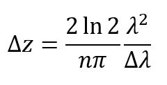 .
.
Here, Δz, is the axial resolution (FWHM of the autocorrelation function) while Δλ is the FWHM of the power spectrum of the SLD light source. The index of refraction (n) of air is ~1, so for a central wavelength (λ) of 1325 nm and a spectral bandwidth of 100 nm, the theoretical axial resolution would be approximately
7.7 µm (see plot). This equation assumes an ideal source with Gaussian spectral distribution. To reduce
side-lobe artifacts that may arise from utilizing non-Gaussian sources, we recommend applying a spectral filter to the detected interferogram. Depending on the filter applied, the actual resolution may be reduced.
Butterfly Package, Type 1
| Pin | Description | Pin | Description |
|---|---|---|---|
| 1 | + TEC | 14 | - TEC |
| 2 | Thermistor | 13 | Case Ground |
| 3 | Not Connected | 12 | Not Connected |
| 4 | Not Connected | 11 | SLD Cathode |
| 5 | Thermistor | 10 | SLD Anode |
| 6 | Not Connected | 9 | Not Connected |
| 7 | Not Connected | 8 | Not Connected |
| Posted Comments: | |
Jang Jin
(posted 2020-07-21 22:29:26.41) I am writing to inquire about SLD1050S-A60 life time.
I look forward to hearing from you in my inquiry soon.
Thank you. YLohia
(posted 2020-07-23 04:58:31.0) Thank you for contacting Thorlabs. We expect the lifetime of the SLD1050S-A60 to be >100,000 hours at 60 mW/950 mA/25 C operating parameters. Murat Yessenov
(posted 2020-05-27 20:07:04.087) Hi!
I wonder if you can make a custom-made SLD at a slightly different wavelength. We are interested in an SLD similar to SLD830S-A20, but centered at or closer to 800 nm?
Thanks! YLohia
(posted 2020-05-28 09:37:32.0) Hello, thank you for contacting Thorlabs. Is there any specific reason that the SLD830S-A20W does not work for your application? This is a broadband SLED and will cover a wide region of wavelengths around 800 nm. I have reached out to you directly to discuss this further. robert
(posted 2017-08-22 09:01:35.56) Dear,
I have one question regarding SLD unit in OCT instruments for example Topcon OCT-2000.
Has a SLD unit lifitime and how we can count this lifetime ? Is this is depending only from how many OCT images has been done or also how many years are old SLD unit.
IS life time is also depending of working hours of SLD for example we have switch on OCT 8 hours every day and we done maybe 20 OCT images.
Thanks a lot for your help.
Regards,
Robert Rimc tfrisch
(posted 2017-09-13 11:22:29.0) Hello, thank you for contacting Thorlabs. Lifetime can be estimated, but it will vary for different operating conditions. I will reach out to you directly to discuss your application. jjurado
(posted 2011-07-12 10:31:00.0) Response from Javier at Thorlabs to last poster: Thank you very much for your feedback. You are correct in asserting that the theoretical resolution is based on the assumption of a Gaussian profile. There are analytical filtering techniques which can be performed to reshape the spectrum of the SLD1325 to provide a Gaussian shape. The actual resolution will sacrifice a bit, but in practice it is nominal. We will add information to the resolution tab shortly to clarify this. Please do not hesitate to contact us at techsupport@thorlabs.com if you have any further questions or comments. user
(posted 2011-07-11 10:41:04.0) The theoretical resolution is based on a gaussian shape. The equation is not valid for this light source, but you suggest it would. Tyler
(posted 2009-02-13 08:11:21.0) A response from Tyler at Thorlabs to xzhao: Thank you for pointing out the units mistake. It has been fixed. xzhao
(posted 2009-02-13 00:30:17.0) Dear Webmaster,
The Spec for SLD1325 should be
Bandwidth* >100 nm
but not
Bandwidth* >100 mW
Thanks,
Xuefeng Zhao
Thorlabs Japan |

 Zoom
Zoom| Item #a | SLD770S | ||
|---|---|---|---|
| Parameter | Min | Typ. | Max |
| Operating Current | - | - | 170 mA |
| Center Wavelength (CWL)b | 760 nm | 770 nm | 780 nm |
| Spectral Shape | Near Gaussian | ||
| ASE Powerc | 4.5 mW | 5.5 mW | - |
| Optical 3 dB Bandwidthc,d | 15 nm | 18 nm | - |
| RMS Gain Ripplec,e | - | 0.01 dB | 0.3 dB |
| Fiber Type | 780HP | ||
| Performance Graphs (Click Icons for Plots) | |||
| Output Spectrum | |||
| LIV Plot | |||
| Gain Ripplee | |||
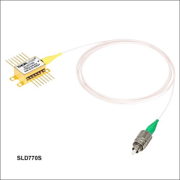
- 770 nm Superluminescent Diode with 18 nm Typical 3 dB Bandwidth
- 5.5 mW Typical Fiber-Coupled Output Power
- Extremely Low Typical Gain Ripple
This superluminescent diode is designed to be used in OCT Systems that require an illumination source with extremely low gain ripple of 0.01 dB (RMS) and a relatively flat spectrum over an 18 nm wide 3 dB bandwidth. It is available with a minimum fiber-coupled output power of 4.5 mW.
Note that the specifications in the table to the right are given as guidelines. The characterization sheet shipped with each SLD provides the minimum, maximum, and recommended operating parameters and specifications specific to that device. Note that the bandwidth will decrease as the current is decreased; bandwidth specifications to the right are specified at the operating current.

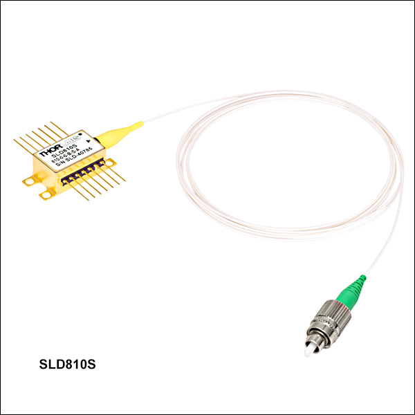 Zoom
Zoom| Item #a | SLD810S | ||
|---|---|---|---|
| Parameter | Min | Typ. | Max |
| Operating Current | - | - | 270 mA |
| Center Wavelength (CWL)b | 795 nm | 810 nm | 825 nm |
| Spectral Shape | Near Gaussian | ||
| ASE Powerc,d | 13 mW | 15 mW | - |
| Optical 3 dB Bandwidthc | 25 nm | 30 nm | - |
| RMS Gain Ripplec,e | - | 0.03 dB | 0.15 dB |
| Fiber Type | 780HP | ||
| Performance Graphs (Click Icons for Plots) | |||
| Output Spectrum | |||
| LIV Plot | |||
| Gain Ripplee | |||
- 810 nm Superluminescent Diodes with 30 nm Typical 3 dB Bandwidth
- 15 mW Typical Fiber-Coupled Output Power
- Extremely Low Typical Gain Ripple
This superluminescent diode is designed to be used in OCT Systems that require an illumination source with extremely low gain ripple of 0.03 dB (RMS) and a relatively flat spectrum over a 30 nm wide 3 dB bandwidth. It is available with a minimum fiber-coupled output power of 13 mW.
Note that the specifications in the table to the right are given as guidelines. The characterization sheet shipped with each SLD provides the minimum, maximum, and recommended operating parameters and specifications specific to that device. Note that the bandwidth will decrease as the current is decreased; bandwidth specifications to the right are specified at the operating current.

 Zoom
Zoom- 830 nm Superluminescent Diodes with 20 nm, 55 nm, 60 nm Typical 3 dB Bandwidth
- Extremely Low Typical Gain Ripple
- 10 mW or 20 mW Minimum Fiber-Coupled Output Power
These superluminescent diodes are designed to be used in OCT Systems that require an illumination source with extremely low gain ripple of 0.03 dB or 0.06 dB (RMS) and a relatively flat spectrum over a 20 nm, 55 nm, or 60 nm wide 3 dB bandwidth. They are available with a minimum fiber-coupled output power of 10 mW or 20 mW.
Note that the specifications in the table below are given as guidelines. The characterization sheet shipped with each SLD provides the minimum, maximum, and recommended operating parameters and specifications specific to that device. Note that the bandwidth will decrease as the current is decreased; bandwidth specifications below are specified at the operating current.
| Item #a | SLD830S-A10W | SLD830S-A20W | SLD830S-A10 | SLD830S-A20 | ||||||||
|---|---|---|---|---|---|---|---|---|---|---|---|---|
| Parameter | Min | Typ. | Max | Min | Typ. | Max | Min | Typ. | Max | Min | Typ. | Max |
| Operating Current | - | - | 240 mA | - | - | 330 mA | - | - | 150 mA | - | - | 240 mA |
| Center Wavelength (CWL)b | 815 nm | 830 nm | 845 nm | 815 nm | 830 nm | 845 nm | 820 nm | 830 nm | 840 nm | 820 nm | 830 nm | 840 nm |
| Spectral Shape | Flat Top | Flat Top | Near Gaussian | Near Gaussian | ||||||||
| ASE Powerc,d | 10 mW | - | - | 20 mW | - | - | 10 mW | 13 mW | - | 20 mW | 22 mW | - |
| Optical 3 dB Bandwidthc,e | 50 nm | 60 nm | - | 40 nm | 55 nm | - | 17 nm | 20 nm | - | 17 nm | 20 nm | - |
| Optical 20 dB Bandwidthc | - | - | - | - | - | - | - | 50 nm | - | - | 50 nm | - |
| RMS Gain Ripplec,f | - | 0.06 dB | 0.3 dB | - | 0.03 dB | 0.3 dB | - | 0.03 dB | 0.15 dB | - | 0.03 dB | 0.15 dB |
| Fiber Type | 780HP | |||||||||||
| Performance Graphs (Click Icons for Plots) | ||||||||||||
| Output Spectrum | ||||||||||||
| LIV Plot | ||||||||||||
| Gain Ripplef | ||||||||||||

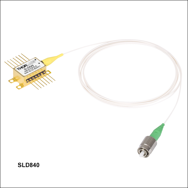 Zoom
Zoom| Item # | SLD840x | ||||
|---|---|---|---|---|---|
| Parametera | Min | Typ. | Max | ||
| Operating Current | - | 140 mA | 180 mA | ||
| Center Wavelength (CWL)b | 820 nm | 840 nm | 860 nm | ||
| Spectral Shape | Flat Top | ||||
| ASE Powerc,d | 3 mW | 4 mW | - | ||
| Optical 3 dB Bandwidthc | 60 nm | 70 nm | - | ||
| RMS Gain Ripplec,e | - | 0.01 dB | 0.1 dB | ||
| Fiber Type | 780HP (SM) PM780-HP (PM)f |
||||
| Performance Graphs (Click Icons for Plots) | |||||
| Output Spectrum |
|
||||
| LIV Plot |
|
||||
| Gain Ripplee |
|
||||
- 840 nm Superluminescent Diodes with 70 nm Typical 3 dB Bandwidth
- 4 mW Typical Fiber-Coupled Output Power
- Extremely Low Typical Gain Ripple of 0.01 dB (RMS)
These superluminescent diodes are designed to be used in OCT Systems that require an illumination source with extremely low typical gain ripple of 0.01 dB (RMS) and a relatively flat spectrum over a 70 nm wide 3 dB bandwidth. They are available with a minimum fiber-coupled output power of 3 mW.
Note that the specifications in the table to the right are given as guidelines. The characterization sheet shipped with each SLD provides the minimum, maximum, and recommended operating parameters and specifications specific to that device. Note that the bandwidth will decrease as the current is decreased; bandwidth specifications to the right are specified at the operating current.

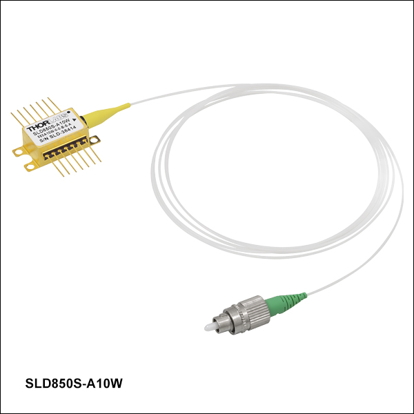 Zoom
Zoom- 850 nm Superluminescent Diodes with 55 nm or 60 nm Typical 3 dB Bandwidth
- 10 mW or 20 mW Minimum Fiber-Coupled Output Power
- Extremely Low Typical Gain Ripple
These superluminescent diodes are designed to be used in OCT Systems that require an illumination source with extremely low typical gain ripple of 0.03 dB (RMS) and a relatively flat spectrum over a 55 nm or 60 nm wide 3 dB bandwidth. They are available with a minimum fiber-coupled output power of 10 mW or 20 mW.
Note that the specifications in the table below are given as guidelines. The characterization sheet shipped with each SLD provides the minimum, maximum, and recommended operating parameters and specifications specific to that device. Note that the bandwidth will decrease as the current is decreased; bandwidth specifications below are specified at the operating current.
| Item #a | SLD850S-A10W | SLD850S-A20W | ||||
|---|---|---|---|---|---|---|
| Parameter | Min | Typ. | Max | Min | Typ. | Max |
| Operating Current | - | - | 180 mA | - | - | 340 mA |
| Center Wavelength (CWL)b | 835 nm | 850 nm | 865 nm | 835 nm | 850 nm | 865 nm |
| Spectral Shape | Flat Top | Flat Top | ||||
| ASE Powerc,d | 10 mW | - | - | 20 mW | - | - |
| Optical 3 dB Bandwidthc,e | 40 nm | 60 nm | - | 40 nm | 55 nm | - |
| RMS Gain Ripplec,f | - | 0.03 dB | 0.3 dB | - | 0.03 dB | 0.3 dB |
| Fiber Type | 780HP | |||||
| Performance Graphs (Click Icons for Plots) | ||||||
| Output Spectrum | ||||||
| LIV Plot | ||||||
| Gain Ripplef | ||||||

 Zoom
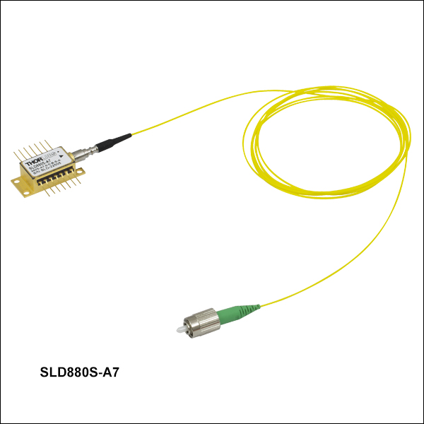
Zoom- 880 nm Superluminescent Diodes with 40 nm Typical 3 dB Bandwidth
- 7 mW or 25 mW Typical Fiber-Coupled Output Power
- FC/APC-Terminated Fiber Pigtail Minimizes Optical Feedback
These superluminescent diodes are designed to be used in OCT Systems. They have a low typical gain ripple of 0.06 dB (RMS) and a relatively flat spectrum over a 40 nm wide 3 dB bandwidth. They are available with a typical fiber-coupled output power of 7 mW or 25 mW.
Note that the specifications in the table below are given as guidelines. The characterization sheet shipped with each SLD provides the minimum, maximum, and recommended operating parameters and specifications specific to that device. Note that the bandwidth will decrease as the current is decreased; bandwidth specifications below are specified at the operating current.
| Item #a | SLD880S-A7 | SLD880S-A25 | ||||
|---|---|---|---|---|---|---|
| Parameter | Min | Typ. | Max | Min | Typ. | Max |
| Operating Current | - | - | 225 mA | - | - | 410 mA |
| Center Wavelength (CWL)b | 860 nm | 880 nm | 900 nm | 860 nm | 880 nm | 900 nm |
| Spectral Shape | Flat Top | Flat Top | ||||
| ASE Powerc,d | 6 mW | 7 mW | - | 23 mW | 25 mW | - |
| Optical 3 dB Bandwidthc | 35 nm | 40 nm | - | 35 nm | 40 nm | - |
| Optical 20 dB Bandwidthc | - | 80 nm | - | - | 80 nm | - |
| RMS Gain Ripplec,e | - | 0.06 dB | 0.3 dB | - | 0.06 dB | 0.3 dB |
| Fiber Type | 780HP | |||||
| Performance Graphs (Click Icons for Plots) | ||||||
| Output Spectrum | ||||||
| LIV Plot | ||||||
| Gain Ripplee | ||||||

 Zoom
Zoom| Item #a | SLD920x | ||
|---|---|---|---|
| Parameter | Min | Typ. | Max |
| Operating Current | - | - | 420 mA |
| Center Wavelength (CWL)b | 895 nm | 920 nm | 945 nm |
| Spectral Shape | Flat Top | ||
| ASE Powerc,d | 10 mW | 15 mW | - |
| Optical 3 dB Bandwidthc | 50 nm | 65 nm | - |
| RMS Gain Ripplec,e | - | 0.02 dB | 0.3 dB |
| Fiber Type | 780HP (SM) PM780-HP (PM)f |
||
| Performance Graphs (Click Icons for Plots) | |||
| Output Spectrum | |||
| LIV Plot | |||
| Gain Ripplee | |||
- 920 nm SLDs with 65 nm Typical 3 dB Bandwidth
- 15 mW Typical Fiber-Coupled Output Power
- FC/APC-Terminated Fiber Pigtail Minimizes Optical Feedback
These superluminescent diodes are designed to be used in OCT Systems. They have a low typical RMS gain ripple of 0.02 dB, a relatively flat spectrum over a 65 nm wide typical 3 dB bandwidth, and 15 mW typical fiber-coupled output power.
Note that the specifications in the table to the right are given as guidelines. The characterization sheet shipped with each SLD provides the minimum, maximum, and recommended operating parameters and specifications specific to that device. Note that the bandwidth will decrease as the current is decreased; bandwidth specifications to the right are specified at the operating current.

 Zoom
Zoom| Item #a | SLD930x-A40W | ||||
|---|---|---|---|---|---|
| Parameter | Min | Typ. | Max | ||
| Operating Current | - | - | 800 mA | ||
| Center Wavelength (CWL)b | 915 nm | 930 nm | 945 nm | ||
| Spectral Shape | Flat Top | ||||
| ASE Powerc,d | 36 mW | 40 mW | - | ||
| Optical 3 dB Bandwidthc | 40 nm | 45 nm | - | ||
| RMS Gain Ripplec,e | - | 0.06 | 0.3 | ||
| Fiber Type | 780HP (SM) PM780-HP (PM)g |
||||
| Performance Graphs (Click Icons for Plots) | |||||
| Output Spectrum |
|
||||
| LIV Plot |
|
||||
| Gain Ripplee |
|
||||
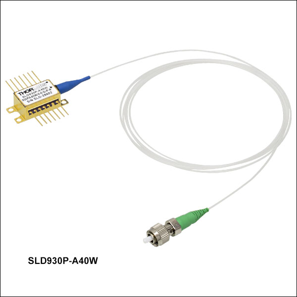
- 930 nm SLDs with 40 nm Typical 3 dB Bandwidth
- 40 mW Typical Fiber-Coupled Output Power
- FC/APC-Terminated Fiber Pigtail Minimizes Optical Feedback
These superluminescent diodes are designed to be used in OCT Systems. They have a low typical RMS gain ripple of 0.06 dB, a relatively flat spectrum over a 45 nm wide typical 3 dB bandwidth, and 40 mW typical fiber-coupled output power.
Note that the specifications in the table to the right are given as guidelines. The characterization sheet shipped with each SLD provides the minimum, maximum, and recommended operating parameters and specifications specific to that device. Note that the bandwidth will decrease as the current is decreased; bandwidth specifications to the right are specified at the operating current.

 Zoom
Zoom| Item #a | SLD970S-A40W | ||
|---|---|---|---|
| Parameter | Min | Typ. | Max |
| Operating Current | - | 1000 mA | 1010 mA |
| Center Wavelength (CWL)b | 945 nm | 970 nm | 995 nm |
| Spectral Shape | Flat Top | ||
| ASE Powerc,d | 35 mW | 40 mW | |
| Optical 3 dB Bandwidthc | 40 nm | 50 nm | |
| RMS Gain Ripplec,e | 0.03 dB | 0.2 dB | |
| Fiber Type | HI1060 (SM) PM980-XP (PM)f |
||
| Performance Graphs (Click Icons for Plots) | |||
| Output Spectrum | |||
| LIV Plot | |||
| Gain Ripplef | |||
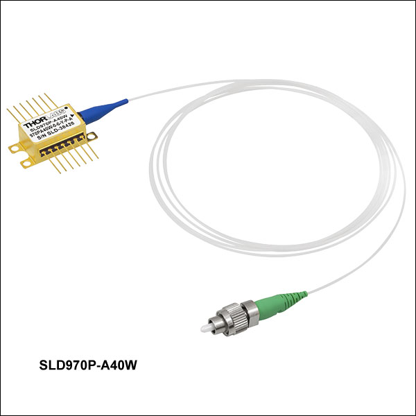
- 970 nm Superluminescent Diodes with 50 nm Typical 3 dB Bandwidth
- 40 mW Typical Fiber-Coupled Output Power
- FC/APC-Terminated Fiber Pigtail Minimizes Optical Feedback
This superluminescent diode is designed to be used in OCT Systems. It has a low typical gain ripple of 0.03 dB (RMS) and a relatively flat spectrum over a 50 nm wide 3 dB bandwidth. This SLD is available with a typical fiber-coupled output power of 40 mW.
Note that the specifications in the table to the right are given as guidelines. The characterization sheet shipped with each SLD provides the minimum, maximum, and recommended operating parameters and specifications specific to that device. Note that the bandwidth will decrease as the current is decreased; bandwidth specifications below are specified at the operating current.

 Zoom
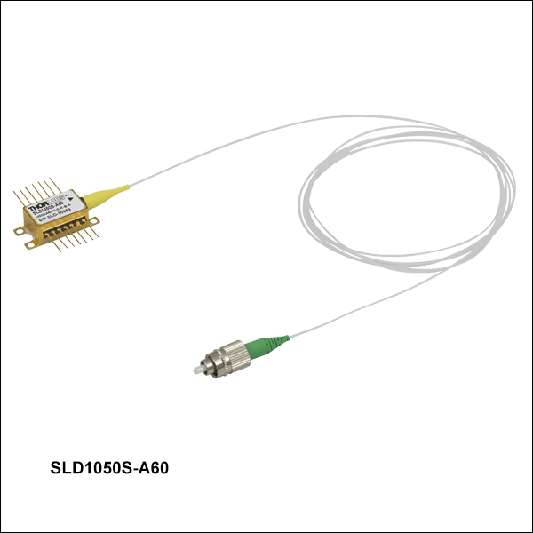
Zoom- 1050 nm Superluminescent Diode with 70 nm Typical 3 dB Bandwidth
- 60 mW Typical Fiber-Coupled Output Power
- FC/APC-Terminated Fiber Pigtail Minimizes Optical Feedback
This superluminescent diode is designed to be used in OCT Systems. It has a low typical gain ripple of 0.03 dB (RMS) and a relatively flat spectrum over a 70 nm wide 3 dB bandwidth. This SLD is available with a typical fiber-coupled output power of 60 mW.
Note that the specifications in the table below are given as guidelines. The characterization sheet shipped with each SLD provides the minimum, maximum, and recommended operating parameters and specifications specific to that device. Note that the bandwidth will decrease as the current is decreased; bandwidth specifications below are specified at the operating current.
| Item #a | SLD1050S-A60 | SLD1050P-A60 | ||||
|---|---|---|---|---|---|---|
| Parameter | Min | Typ. | Max | Min | Typ. | Max |
| Operating Current | - | - | 1010 mA | - | - | 1010 mA |
| Center Wavelength (CWL)b | 1025 nm | 1050 nm | 1075 nm | 1025 nm | 1050 nm | 1075 nm |
| Spectral Shape | Flat Top | Flat Top | ||||
| ASE Powerc,d | 55 mW | 60 mW | - | 55 mW | 60 mW | - |
| Optical 3 dB Bandwidthc | 60 nm | 70 nm | - | 60 nm | 70 nm | - |
| Optical 20 dB Bandwidthc | - | 100 nm | - | - | - | - |
| RMS Gain Ripplec,e | - | 0.03 dB | 0.2 dB | - | 0.06 dB | 0.2 dB |
| Fiber Type | HI1060 | PM980-XPf | ||||
| Performance Graphs (Click Icons for Plots) | ||||||
| Output Spectrum | ||||||
| LIV Plot | ||||||
| Gain Ripplee | ||||||

 Zoom
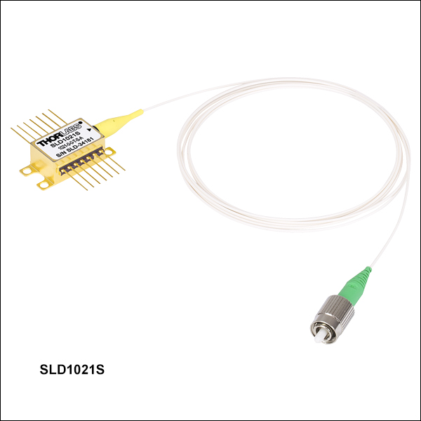
Zoom- 1310 nm Superluminescent Diodes with 70 nm Typical 3 dB Bandwidth
- 12.5 mW or 30 mW Typical Fiber-Coupled Output Power
- FC/APC-Terminated Fiber Pigtail Minimizes Optical Feedback
These superluminescent diodes are designed to be used in OCT Systems. They have a low max gain ripple of 0.35 dB (RMS) and a relatively flat spectrum over an 85 nm wide 3 dB bandwidth. They are available with a typical fiber-coupled output power of 12.5 mW. A dual-stage optical isolator is integrated into the SLD1310 and SLD1310P providing a typical of 50 dB optical isolation.
Note that the specifications in the table below are given as guidelines. The characterization sheet shipped with each SLD provides the minimum, maximum, and recommended operating parameters and specifications specific to that device. Note that the bandwidth will decrease as the current is decreased; bandwidth specifications below are specified at the operating current.
| Item #a | SLD1021S | SLD1310 | SLD1310P | ||||||
|---|---|---|---|---|---|---|---|---|---|
| Parameter | Min | Typ. | Max | Min | Typ. | Max | Min | Typ. | Max |
| Operating Current | - | 700 mA | 900 mA | - | 900 mA | 1000 mA | - | 900 mA | 1000 mA |
| Center Wavelength (CWL)b | 1290 nm | - | 1330 nm | 1300 nm | 1315 nm | 1330 nm | 1300 nm | 1315 nm | 1330 nm |
| Spectral Shape | Near Gaussian | Flat Top | Flat Top | ||||||
| ASE Powerc,d | 10 mW | 12.5 mW | - | 22 mW | 30 mW | - | 22 mW | 30 mW | - |
| Optical 3 dB Bandwidthc,d,e | 80 nm | 85 nm | - | 75 nm | 90 nm | - | 75 nm | 90 nm | - |
| RMS Gain Ripplec,f | - | - | 0.35 dB | - | 0.12 dB | 0.3 dB | - | 0.12 | 0.3 |
| Polarization Extinction Ratio (PER) | - | - | - | - | - | - | - | 23 dB | - |
| Fiber Type | SMF-28e+ | SMF-28e | Corning® PM13-U40Ag | ||||||
| Integrated Optical Isolator | |||||||||
| Isolation | N/Ah | - | 50 dB | - | - | 50 dB | - | ||
| Performance Graphs (Click Icons for Plots) | |||||||||
| Output Spectrum | |||||||||
| LIV Plot | |||||||||
| Gain Ripplef | - | ||||||||

 Zoom
Zoom- 1325 nm Center Wavelength with 90 nm or >100 nm Bandwidth
- 10 mW Minimum or 40 mW Typical Fiber-Coupled Output Power
- Integrated Optical Isolator for Enhanced Output Stability
- FC/APC-Terminated Fiber Pigtail Minimizes Optical Feedback
The SLD1325 and SLD1330x SLDs have a typical center wavelength of 1325 nm and are designed to have broad 3 dB bandwidths of >100 nm or 90 nm (typical) respectively, making them ideal for high-axial-resolution SD-OCT applications (see the Resolution SD-OCT tab above for more information). These SLDs are packaged with an integrated TEC and thermistor for temperature control, as well as an optical isolator for enhanced optical stability. The isolator in the SLD1325 SLD provides 30 dB minimum of isolation while the isolators in the SLD1330 and SLD1330P SLDs provide 50 dB of isolation.
Note that the specifications in the table below are given as guidelines. The characterization sheet shipped with each SLD provides the minimum, maximum, and recommended operating parameters and specifications specific to that device. Note that the bandwidth will decrease as the current is decreased; bandwidth specifications below are specified at the operating current.
| Item #a | SLD1325 | SLD1330 | SLD1330P | ||||||
|---|---|---|---|---|---|---|---|---|---|
| Parameter | Min | Typ. | Max | Min | Typ. | Max | Min | Typ. | Max |
| Operating Current | - | - | 780 mA | - | 1250 mA | 1300 mA | - | 1250 mA | 1300 mA |
| Center Wavelength (CWL)b | - | 1325 nm | - | 1310 nm | 1325 nm | 1340 nm | 1310 nm | 1325 nm | 1340 nm |
| Spectral Shape | Flat Top | Flat Top | Flat Top | ||||||
| ASE Powerc,d | 10 mW | - | - | 35 mW | 40 mW | - | 35 mW | 40 mW | - |
| 3 dB Optical Bandwidthc,d,e | 100 nm | - | - | 80 nm | 90 nm | - | 80 nm | 90 nm | - |
| RMS Gain Ripplec,f | - | 0.1 dB | 0.3 dB | - | 0.1 dB | 0.3 dB | |||
| Polarization Extinction Ratio (PER) | - | - | - | - | - | - | - | 23 dB | - |
| Fiber Type | SMF-28e | SMF-28e | Corning® PM13-U40Ag | ||||||
| Integrated Optical Isolator | |||||||||
| Isolation | 30 dB | - | - | - | 50 dB | - | - | 50 dB | - |
| Performance Graphs (Click Icons for Plots) | |||||||||
| Output Spectrum | |||||||||
| LIV Plot | |||||||||
| Gain Ripplef | - | ||||||||

 Zoom
Zoom| Item #a | SLD1410x | ||||
|---|---|---|---|---|---|
| Parameter | Min | Typ. | Max | ||
| Operating Current | - | 600 mA | 700 mA | ||
| Center Wavelength (CWL)b | 1385 nm | 1400 nm | 1415 nm | ||
| Spectral Shape | Near Gaussian | ||||
| ASE Powerc,d | 4 mW | 5 mW | - | ||
| Optical 3 dB Bandwidthc,e | 90 nm | 98 nm | - | ||
| RMS Gain Ripplec,f | - | 0.2 dB | 0.6 dB | ||
| Fiber Type | SMF-28e (SM) Corning® PM13-U40A (PM) |
||||
| Integrated Optical Isolator | |||||
| Isolation | 30 dB | ||||
| Performance Graphs (Click Icons for Plots) | |||||
| Output Spectrum |
|
||||
| LIV Plot |
|
||||
| Gain Ripplee |
|
||||
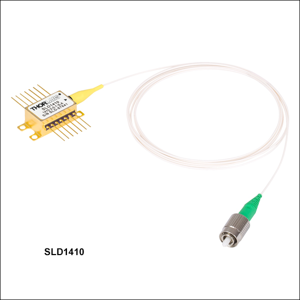
- 1400 nm Superluminescent Diodes with 98 nm Typical 3 dB Bandwidth
- 5 mW Typical Fiber-Coupled Output Power
- Integrated Optical Isolator for Enhanced Output Stability
- FC/APC-Terminated Fiber Pigtail Minimizes Optical Feedback
These superluminescent diodes are designed to be used in OCT Systems that require an illumination source with extremely low gain ripple of 0.2 dB (RMS) and a relatively flat spectrum over a 98 nm wide 3 dB bandwidth. They are packaged with an integrated TEC and thermistor for temperature control, as well as an optical isolator which provides 30 dB of isolation for enhanced optical stability. The minimum fiber-coupled output power is 4 mW.
Note that the specifications in the table to the right are given as guidelines. The characterization sheet shipped with each SLD provides the minimum, maximum, and recommended operating parameters and specifications specific to that device. Note that the bandwidth will decrease as the current is decreased; bandwidth specifications to the right are specified at the operating current.

 Zoom
Zoom| Item #a | SLD1450x | ||||
|---|---|---|---|---|---|
| Parameter | Min | Typ. | Max | ||
| Operating Current | - | 500 mA | 600 mA | ||
| Center Wavelength (CWL)b | 1435 nm | 1450 nm | 1465 nm | ||
| Spectral Shape | Near Gaussian | ||||
| ASE Powerc,d | 23 mW | 25 mW | - | ||
| Optical 3 dB Bandwidthc | 50 nm | 54 nm | - | ||
| RMS Gain Ripplec,e | - | 0.06 dB | 0.35 dB | ||
| Fiber Type | SMF-28e (SM) Corning® PM15-U40A (PM) |
||||
| Performance Graphs (Click Icons for Plots) | |||||
| Output Spectrum |
|
||||
| LIV Plot |
|
||||
| Gain Ripplee |
|
||||
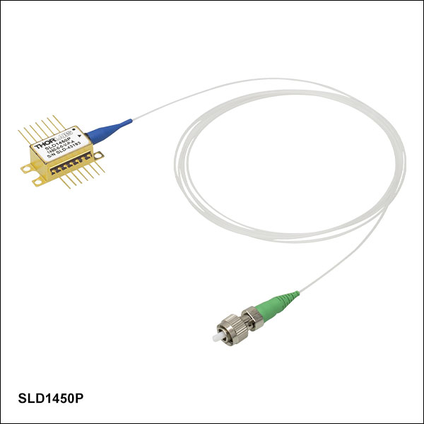
- 1450 nm Superluminescent Diodes with 54 nm Typical 3 dB Bandwidth
- 25 mW Typical Fiber-Coupled Output Power
- Extremely Low Typical Gain Ripple
This superluminescent diode is designed to be used in OCT Systems that require an illumination source with extremely low gain ripple of 0.06 dB (RMS) and a relatively flat spectrum over a 54 nm wide 3 dB bandwidth. It is available with a minimum fiber-coupled output power of 23 mW.
Note that the specifications in the table to the right are given as guidelines. The characterization sheet shipped with each SLD provides the minimum, maximum, and recommended operating parameters and specifications specific to that device. Note that the bandwidth will decrease as the current is decreased; bandwidth specifications to the right are specified at the operating current.

 Zoom
Zoom| Item #a | SLD1610x | ||||
|---|---|---|---|---|---|
| Parameter | Min | Typ. | Max | ||
| Operating Current | - | 800 mA | 900 mA | ||
| Center Wavelength (CWL)b | 1590 nm | 1610 nm | 1630 nm | ||
| Spectral Shape | Near Gaussian | ||||
| ASE Powerc,d | 22 mW | 27 mW | - | ||
| Optical 3 dB Bandwidthc | 50 nm | 57 nm | - | ||
| RMS Gain Ripplec,e | - | 0.2 dB | 0.5 dB | ||
| Fiber Type | SMF-28e (SM) Corning® PM15-U40A (PM) |
||||
| Performance Graphs (Click Icons for Plots) | |||||
| Output Spectrum |
|
||||
| LIV Plot |
|
||||
| Gain Ripplee |
|
||||
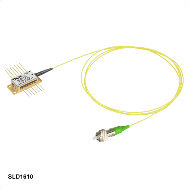
- 1610 nm Superluminescent Diodes with 57 nm Typical 3 dB Bandwidth
- 27 mW Typical Fiber-Coupled Output Power
- Extremely Low Typical Gain Ripple
This superluminescent diode is designed to be used in OCT Systems that require an illumination source with extremely low gain ripple of 0.2 dB (RMS) and a relatively flat spectrum over a 57 nm wide 3 dB bandwidth. It is available with a minimum fiber-coupled output power of 22 mW.
Note that the specifications in the table to the right are given as guidelines. The characterization sheet shipped with each SLD provides the minimum, maximum, and recommended operating parameters and specifications specific to that device. Note that the bandwidth will decrease as the current is decreased; bandwidth specifications to the right are specified at the operating current.