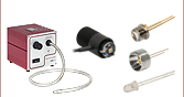
 Products Home
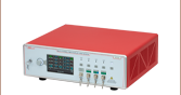
Benchtop SLD Light Sources

- Superluminescent Diodes (SLDs) with Broadband
Emission Centered at 1050, 1310, or 1550 nm - Temperature Stabilized Using a TEC
- FC/APC Bulkhead Connector
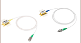
S5FC1018S
SM Fiber Coupled,
1310 nm
S5FC1050P
PM Fiber Coupled,
1050 nm


Please Wait
| Table 1.1 Key Specifications | ||||
|---|---|---|---|---|
| Item #a | Wavelength | Output Power | Bandwidth @ -3 dB | Internal Pigtailed Diode |
| SM Fiber-Coupled Benchtop SLDs | ||||
| S5FC1021S | 1310 nm | 12.5 mW | 85 nm | SLD1021S |
| S5FC1018S | 1310 nm | 30 mW | 45 nm | SLD1018S |
| S5FC1550S-A2 | 1550 nm | 2.5 mW | 90 nm | SLD1550P-A2 |
| S5FC1005S | 1550 nm | 22 mW | 50 nm | SLD1005S |
| PM Fiber-Coupled Benchtop SLDs | ||||
| S5FC1050P | 1050 nm | 8 mW | 50 nm | SLD1050P |
| S5FC1021P | 1310 nm | 12.5 mW | 85 nm | N/A |
| S5FC1018P | 1310 nm | 30 mW | 45 nm | SLD1018P |
| S5FC1550P-A2 | 1550 nm | 2.5 mW | 90 nm | SLD1550P-A2 |
| S5FC1005P | 1550 nm | 22 mW | 50 nm | N/A |
- For a complete list of specifications, click on the info icons (
 ) in Tables G1.1 through G2.2.
Features
- Broadband Emission Centered at 1050 nm, 1310 nm or 1550 nm
- Single Mode (SM) or Polarization-Maintaining (PM) Output with FC/APC, 2.0 mm Narrow Key Connector
- TEC for Temperature Stabilization
- Low Output Noise: <0.1%
- USB 2.0 Interface for Remote Operation
- Each Unit Ships with a Complete Test Report
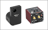
Thorlabs' Fiber-Coupled SLD Sources are benchtop units that have an integrated superluminescent diode (SLD), controller, and TEC. These sources produce broadband emission centered at 1050 nm, 1310 nm, or 1550 nm and the output is coupled to an FC/APC connector. The center wavelength with these devices, as with all broadband devices, is defined by an average weighted by the relative amplitude and may not correspond to peak power or the FWHM center wavelength due to the asymmetry of the spectrum.
The 1050 nm SLD source is available with PM fiber output, while the other wavelengths are available from stock with either SM or PM fiber outputs. See Table 1.1 for a summary of available sources. Please note that optical feedback can diminish the output power or damage the SLD source. We do not recommend using these SLD sources with components that are prone to back reflections, such as FC/PC connectors. Custom units with different connectors, fibers, or an optical isolator incorporated into the unit are available upon request by contacting Tech Support.
An intuitive LCD interface on the front of the unit allows the user to view the parameters for the SLD. For more details, please see the Operation tab. A USB 2.0 connector is provided for remotely enabling the SLD and adjusting the temperature and power. On the rear panel, an analog input is available to modulate the SLD with an external signal of 0 to 5 V, which is added to the internal setpoint. To prevent damage, an integrated microcontroller will disable the output if the analog input plus the internal setpoint exceeds the SLD limits.
The SLDs in these benchtop sources are operated using an independent, high-precision, low-noise constant current source and temperature control unit. The integrated microcontroller fully regulates the SLD's optical power and temperature as well as monitors the system for fault conditions.
Superluminescent diodes are excellent high-power broadband light sources for use in applications such as Optical Coherence Tomography (OCT) and Fiber Optic Gyroscopes (FOG). The SLDs offered here are indium phosphide (InP) devices. For safety, most of Thorlabs' SLDs are designed with housing that meets 3B laser requirements; with a key switch, 3B compliant interlocking features, an installed dust cap, and a power on warning with a five second blinking light. Furthermore, the color of the LED will not interfere with laser glass. To see which SLDs have 3B compliant housing, see below. For more information on what 3B compliance is, please refer to the Laser Safety tab.
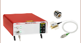
The S5FC includes a universal power supply allowing operation over 100 to 240 VAC without the need for selecting the line voltage. The fuse access is conveniently located on the rear panel.
We also offer custom wavelength benchtop SLD sources to meet the needs of customers whose applications are not covered by our stock selection. Contact Tech Support for more information.

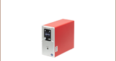
Click to Enlarge
Figure 2.1 Benchtop SLD Light Source Front Panel
Viewing Information
Thorlabs' SLDs use a single four quadrant LCD to display information as shown in Figure 2.1 (2) Digital Display with Backlight.
- Top Left: Indicates device type.
- Top Right: Indicates the wavelength of the SLD.
- Bottom Left: If a monitor diode is included in the pigtailed diode, a power reading (in mW) will be displayed. When enabled, the current power level determined from the monitor photodiode will indicate the approximate power level of the output. When disabled, the power level will read "0.00 mW". If a monitor diode is not included in the pigtailed diode, a current reading (in mA) will be indicated instead.
- Bottom Right: Indicates the actual temperature (in °C) the SLD is stabilized to. The default temperature is set to 25.00 °C and is user adjustable.
Adjusting the SLD Output Power and Temperature
The control knob/switch utilizes an intelligent speed control. Turning the knob slowly corresponds to fine adjustment while turning the knob quickly corresponds to coarse adjustment. The SLD current threshold is a user-selectable command parameter that allows the user to filter out nonlinear sections of the SLD power curve. The threshold current is defaulted to 1 mA on initial power up.
The unit will be in Display Mode when it is first turned on to show the variables such as power reading, temperature, and wavelength. Pressing the control knob/switch once enables the Current Control Mode. Simply turn the knob will allow the user to adjust the current. Pressing the control knob one more time enables Temperature Control Mode. The user will be able to adjust temperature in this mode. The resolution for the current adjustment is 0.1 mA and 0.01 °C for temperature adjustment.
Modulating the SLD Output
The Analog In input can be used to modulate the SLD output or to set the SLD output remotely using a 5 V power source. The 5 V maximum input corresponds to the maximum calibrated power, which operates the SLD using a constant current drive technique. The resulting actual output power is dependent on the set current and operating temperature.
In addition, in order to eliminate a dead zone in the power control knob, the output of the unit is offset to the threshold current of the coupled SLD diode. Adjusting the knob below threshold will immediately set the current to 0.0 mA, or Standby mode. Therefore, there are two modes of modulation available. First, setting the control to "Standby" allows the analog modulation to utilize the full 0 to 5 V input range. The drawback is that a minimum voltage will be required to operate above the threshold current but allows more flexibility by the user. The second mode is to adjust the control knob so that the SLD is at threshold or above. The analog modulation voltage will be limited to less than the full 0 to 5 V range, but a DC offset will not be required. This should be kept in mind when using the modulation input since it will limit the actual input voltage range.
Making the Safety Interlock Connections
The S5FC series of SLD sources are equipped with a remote interlock connector located on the rear panel. All units have this feature regardless of their FDA and IEC classifications. In order to enable the S5FC source, a short circuit must be applied across the terminals of the Remote Interlock connector. In practice this connection is made available to allow the user to connect a remote-actuated switch to the connector (i.e., an open door indicator). The switch (which must be normally open) has to be closed in order for the unit to be enabled. Once the switch is in an open state, the S5FC source will automatically shut down. If the switch returns to a closed condition, the S5FC source must be re-enabled at the unit by pressing the ENABLE switch.
| Specification | Value |
|---|---|
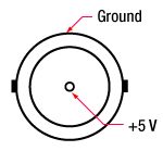
| Type of Mating Connector | 2.5 mm Mono Phono Jack |
| Open Circuit Voltage | Internal Pull Up to 5 VDC |
| Short Circuit Current | 10 mA DC |
| Interlock Switch Requirementsa | Must be Normally Open, Dry Contacts |
Modulation Input
BNC Female
0 to 5 V
Remote Interlock Input
2.5 mm Mono Phono Jack

Terminals must be shorted either by included plug or user device, i.e. external switch, for laser mode "ON" to be enabled.
Computer Connection
USB Type B
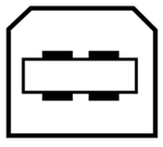
USB Type A to Type B Cable Included
Software
Version 1.2.0
Software package to operate Thorlabs' Benchtop Fiber-Coupled SLD Light Sources, including a GUI, drivers, and LabVIEW/C++ SDK for secondary development.
Laser Safety and Classification
Safe practices and proper usage of safety equipment should be taken into consideration when operating lasers. The eye is susceptible to injury, even from very low levels of laser light. Thorlabs offers a range of laser safety accessories that can be used to reduce the risk of accidents or injuries. Laser emission in the visible and near infrared spectral ranges has the greatest potential for retinal injury, as the cornea and lens are transparent to those wavelengths, and the lens can focus the laser energy onto the retina.
 |
 |
 |
 |
 |
 |
 |
 |
 |
Safe Practices and Light Safety Accessories
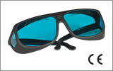
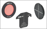
- Laser safety eyewear must be worn whenever working with Class 3 or 4 lasers.
- Regardless of laser class, Thorlabs recommends the use of laser safety eyewear whenever working with laser beams with non-negligible powers, since metallic tools such as screwdrivers can accidentally redirect a beam.
- Laser goggles designed for specific wavelengths should be clearly available near laser setups to protect the wearer from unintentional laser reflections.
- Goggles are marked with the wavelength range over which protection is afforded and the minimum optical density within that range.
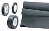
- Laser Safety Curtains and Laser Safety Fabric shield other parts of the lab from high energy lasers.
- Blackout Materials can prevent direct or reflected light from leaving the experimental setup area.
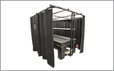
- Thorlabs' Enclosure Systems can be used to contain optical setups to isolate or minimize laser hazards.
- A fiber-pigtailed laser should always be turned off before connecting it to or disconnecting it from another fiber, especially when the laser is at power levels above 10 mW.
- All beams should be terminated at the edge of the table, and laboratory doors should be closed whenever a laser is in use.
- Do not place laser beams at eye level.
- Carry out experiments on an optical table such that all laser beams travel horizontally.
- Remove unnecessary reflective items such as reflective jewelry (e.g., rings, watches, etc.) while working near the beam path.
- Be aware that lenses and other optical devices may reflect a portion of the incident beam from the front or rear surface.
- Operate a laser at the minimum power necessary for any operation.
- If possible, reduce the output power of a laser during alignment procedures.
- Use beam shutters and filters to reduce the beam power.
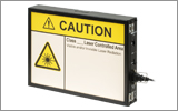
- Post appropriate warning signs or labels near laser setups or rooms.
- Use a laser sign with a lightbox if operating Class 3R or 4 lasers (i.e., lasers requiring the use of a safety interlock).
- Do not use Laser Viewing Cards in place of a proper Beam Trap.
Laser Classification
Lasers are categorized into different classes according to their ability to cause eye and other damage. The International Electrotechnical Commission (IEC) is a global organization that prepares and publishes international standards for all electrical, electronic, and related technologies. The IEC document 60825-1 outlines the safety of laser products. A description of each class of laser is given below:
| Class | Description | Warning Label |
|---|---|---|
| 1 | This class of laser is safe under all conditions of normal use, including use with optical instruments for intrabeam viewing. Lasers in this class do not emit radiation at levels that may cause injury during normal operation, and therefore the maximum permissible exposure (MPE) cannot be exceeded. Class 1 lasers can also include enclosed, high-power lasers where exposure to the radiation is not possible without opening or shutting down the laser. | 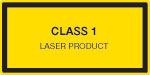 |
| 1M | Class 1M lasers are safe except when used in conjunction with optical components such as telescopes and microscopes. Lasers belonging to this class emit large-diameter or divergent beams, and the MPE cannot normally be exceeded unless focusing or imaging optics are used to narrow the beam. However, if the beam is refocused, the hazard may be increased and the class may be changed accordingly. | 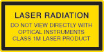 |
| 2 | Class 2 lasers, which are limited to 1 mW of visible continuous-wave radiation, are safe because the blink reflex will limit the exposure in the eye to 0.25 seconds. This category only applies to visible radiation (400 - 700 nm). | 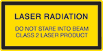 |
| 2M | Because of the blink reflex, this class of laser is classified as safe as long as the beam is not viewed through optical instruments. This laser class also applies to larger-diameter or diverging laser beams. | 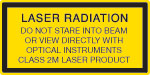 |
| 3R | Class 3R lasers produce visible and invisible light that is hazardous under direct and specular-reflection viewing conditions. Eye injuries may occur if you directly view the beam, especially when using optical instruments. Lasers in this class are considered safe as long as they are handled with restricted beam viewing. The MPE can be exceeded with this class of laser; however, this presents a low risk level to injury. Visible, continuous-wave lasers in this class are limited to 5 mW of output power. | 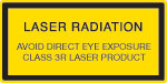 |
| 3B | Class 3B lasers are hazardous to the eye if exposed directly. Diffuse reflections are usually not harmful, but may be when using higher-power Class 3B lasers. Safe handling of devices in this class includes wearing protective eyewear where direct viewing of the laser beam may occur. Lasers of this class must be equipped with a key switch and a safety interlock; moreover, laser safety signs should be used, such that the laser cannot be used without the safety light turning on. Laser products with power output near the upper range of Class 3B may also cause skin burns. | 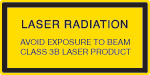 |
| 4 | This class of laser may cause damage to the skin, and also to the eye, even from the viewing of diffuse reflections. These hazards may also apply to indirect or non-specular reflections of the beam, even from apparently matte surfaces. Great care must be taken when handling these lasers. They also represent a fire risk, because they may ignite combustible material. Class 4 lasers must be equipped with a key switch and a safety interlock. | 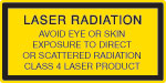 |
| All class 2 lasers (and higher) must display, in addition to the corresponding sign above, this triangular warning sign. |  |
|
| Posted Comments: | |
user
(posted 2023-11-16 07:55:51.73) how well ist the polarization of the source aligned to the output fiber. Can you express this as Polarization Ratio? We need at least 40dB Polarization ratio ksosnowski
(posted 2023-11-20 11:30:44.0) Thanks for reaching out to Thorlabs. In this case the PER is limited by the SLD emitter rather than the fiber axis alignment. We typically expect PER close to 18dB however we consider 15dB as a safe estimate overall. Unfortunately, 40dB is beyond our current capabilities on these devices. Quan-Shan Liu
(posted 2023-09-12 11:24:13.783) Dear Thorlabs Team,
May I know whether this item needs a warm-up prior to measurements?
Thanks,
Quan-Shan Liu ksosnowski
(posted 2023-09-12 10:02:52.0) Hello Quan-Shan, thanks for reaching out to Thorlabs. When the SLD benchtop unit is turned on, the TEC is activated. Even if the SLD optical output is not activated yet, the TEC will be active. The S5FC temperature typically requires up to 2 minutes to stabilize. I've reached out directly to discuss this further. user
(posted 2022-11-15 20:59:49.143) Please tell me why 1320nm is displayed in the upper right corner of the 1310nm light source display? Isn't the output wavelength of this light source 1310nm? ksosnowski
(posted 2022-11-15 09:57:13.0) Hello, thanks for reaching out to Thorlabs. The central wavelength of the installed diode is programmed to the unit and displayed on the S5FC panel. The exact value can vary between units however the central wavelength specification for S5FC1018S is 1290nm (min) - 1330nm (max). Changing the operating current and temperature may also shift the central wavelength of the SLD. These are not intended to be tuned significantly using temperature or current. I have reached out directly to discuss this further. user
(posted 2021-07-26 18:05:09.943) Hi, could you please tell me the fiber core diameter for S5FC1021P? Thanks. YLohia
(posted 2021-07-26 11:18:41.0) Hello, the S5FC1021P contains the SLD1018P pigtailed SLD package, which has the SMF-28e+ fiber. This fiber is specified for an MFD of 9.2 ± 0.4 μm @ 1310 nm. ZHANG Luan
(posted 2021-04-21 02:44:41.23) Hi,
Could you please tell me whether there is an isolator inside S5FC1005S?
Thanks a lot! YLohia
(posted 2021-04-21 11:35:25.0) Hello, these benchtop sources do not contain integrated isolators. Custom units with integrated isolators can be requested by using the "Request Quote" button above. jlow
(posted 2013-01-22 17:09:00.0) Response from Jeremy at Thorlabs: Unfortunately we do not have a LabVIEW module for this. However, you should be able to make your own using the serial commands listed in the manual of the S5FC1018S (page 14 of the manual). kohsce
(posted 2013-01-11 03:54:23.343) I am using Labview to control a S5FC1018S, but the data readback is rather slow and in a series of strings.
do you have a labvew module to control this SLD? Adam
(posted 2010-04-26 23:23:53.0) A response from Adam at Thorlabs to c.j: The SLDs used in the Benchtop sources do not have internal isolators. We can offer this as a custom option. Whether or not an external isolator is required between the benchtop unit and experiment will depend on the sensitivity of the experiment to any changes in the spectral ripple due to feedback. Strong reflections back into the SLD will cause an increase in spectral ripple, however, if the return loss is less the -20 dB then there most likely isnt a need for an isolator. Again, this depends on the sensitivity of the experiment. I will contact you directly to get more information. c.j.lee
(posted 2010-04-26 15:32:21.0) How sensitive is the product to optical feedback? Is it optically isolated, or should we expect to place an isolator between it and the experiment? |
| Table G1.1 Specifications | ||||
|---|---|---|---|---|
| Item # | Wavelength | Output Power | Laser Class | More Info |
| S5FC1021S | 1310 nm | 12.5 mW | 1Ma | |
| S5FC1018S | 1310 nm | 30 mW | 1Ma | |
| Table G1.2 Specifications | ||||
|---|---|---|---|---|
| Item # | Wavelength | Output Power | Laser Class | More Info |
| S5FC1550S-A2 | 1550 nm | 2.5 mW | 1Ma | |
| S5FC1005S | 1550 nm | 22 mW | 1Ma | |
| Table G2.1 Specifications | ||||
|---|---|---|---|---|
| Item # | Wavelength | Output Power | Laser Class | More Info |
| S5FC1050P | 1050 nm | 8 mW | 1M | |
| S5FC1021P | 1310 nm | 12.5 mW | 1Ma | |
| S5FC1018P | 1310 nm | 30 mW | 1Ma | |
| Table G2.2 Specifications | ||||
|---|---|---|---|---|
| Item # | Wavelength | Output Power | Laser Class | More Info |
| S5FC1550P-A2 | 1550 nm | 2.5 mW | 1Ma | |
| S5FC1005P | 1550 nm | 22 mW | 1Ma | |