 Products Home / Drivers & Mounts / Dual Current / Temperature Controllers / Combined Laser Diode and TEC Controllers
Combined Laser Diode and TEC Controllers
- Provides Laser Currents up to 1 A, 2 A, 5 A, or 20 A
- Supports TEC Currents up to ±8 A or ±15 A
- 17 V and 20 V Compliance Voltage Versions for Driving QCL and ICL Lasers
- Excellent 24 Hour Temperature Stability (0.002 °C)
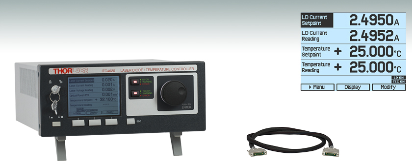
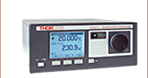
ITC4020
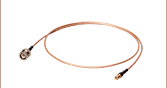
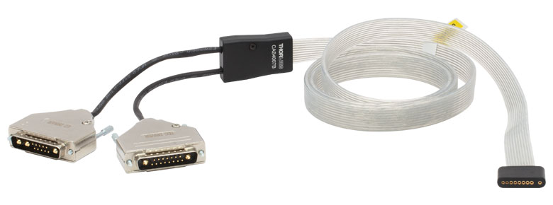
CAB4001
The main measurement display
shows readout values and device
status information.


Please Wait
Laser Diode Controller Features
- Operate with Anode- or Cathode-Grounded Laser Diodes and Photodiodes
- 17 V and 20 V Compliance Voltage Versions Capable of Driving High-Power QCLs
- Continuous Wave (CW) or Quasi-Continuous Wave (QCW) Operation
- Also Capable of Driving LEDs
- Internal Function Generator for Analog Modulation
- External Modulation Input
- Analog Monitor Output for the Laser Current
- Laser Diode Voltage Measurement
- Active Power Management for Efficient Operation
- Compatible Optical Detectors
- Photodiodes
- Thermopiles
- Common Sensor Amplifiers
- Power Meters with Voltage Output
- Laser Diode Control Modes
- Constant Current (CC)
- Constant Power (CP)
- Enhanced Laser Diode Protection Features
- Adjustable Laser Current Limit
- Adjustable Laser Power Limit
- Laser Over Voltage Protection
- Over Temperature Protection
TEC Controller Features
- Excellent Temperature Stability:
0.002 °C (24 hrs) - Digital PID Control with Separate
P, I, D Settings - Auto PID Tuning Function
- Adjustable Temperature Sensor Offset
- Compatible Temperature Sensors
- NTC Thermistors
- Current Temperature Sensors
- Voltage Temperature Sensors
- Platinum RTD Temperature Sensors
- TEC Control Modes
- Constant Temperature
- Constant Current
- Enhanced TEC Security Features
- Adjustable TEC
Current Limit - Adjustable Temperature Limits
- Temperature Window Protection
- Fault Connection and Sensor Alarm
| Item #a | ITC4001 | ITC4002QCL | ITC4005 | ITC4005QCL | ITC4020 |
|---|---|---|---|---|---|
| Current Control Range | 0 to 1 A | 0 to 2 A | 0 to 5 A | 0 to 5 A | 0 to 20 A |
| Compliance Voltage | 11 V | 17 Vb | 12 V | 20 Vb | 11 V |
| Photocurrent Measurement Ranges | 2 mA / 20 mA | ||||
| QCWc Mode Pulse Width Range | 100 µs to 1 s | ||||
| QCWc Repetition Rate Range | 1 ms to 5 s (0.2 to 1000 Hz) | ||||
| TEC Current Ranged | -8 to +8 A | -15 to +15 A | |||
| TEC Compliance Voltage | >12 V | >15 V | |||
| TEC Output Power (Max) | >96 W | >225 W | |||
| Temperature Range (Max) | -150 to +150 °Ce | ||||
| Supported Temperature Sensors | Thermistors (TH10K), Pt100 (TH100PT), Pt1000, AD590, AD592, LM335, LM235, LM135, LM35 |
||||
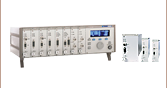
Thorlabs' Combined Laser Diode and TEC Controllers combine the functionality of a LDC4000 series current controller and a TED4015 temperature controller in a single device. They are designed to provide precise, stable current for laser diodes with maximum operating currents from 1 to 20 A (see the table to the lower right for details) and excellent temperature stabilization to within 0.002 °C over a period of 24 hours. In addition to our standard versions which have a compliance voltage of 11 or 12 V, we offer two high-compliance-voltage drivers for our QCL and ICL lasers: the ITC4002QCL can provide up to 17 V at 2 A of current and the ITC4005QCL can provide up to 20 V at 5 A of current. For optimal noise performance, choose a controller that has maximum current and voltage ratings as close as possible to, but still higher than, the required voltage and current needed to operate your laser.
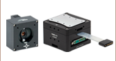
The controllers are compatible with all laser diode and monitor diode pin configurations and feature a constant current (CC) or constant power (CP) mode. Most common temperature sensors can be used, and the ITC4000 can be adapted to different thermal loads via a digital PID controller. It offers an auto-tune PID function or separate control of the P, I, and D parameters. For more details about these features please see the More Info tab. The controllers are also compatible with our line of laser mounts, some of which also include TEC elements.
The ITC4000 devices are controlled via front panel keys and intuitive operation menus on a large and easy-to-read graphic LCD display (see the Display tab for sample screens). Additionally, these controllers can be controlled by a SCPI-compatible USB Interface. A higher setting and measurement resolution is offered via USB operation since the front panel resolution is limited by the resolution of the display. Various outputs and a digital I/O port offer many control and connectivity options. The built-in function generator allows analog modulation of the laser output out of the box.
These controllers offer many advanced features such as Quasi-Continuous Wave (QCW) operation mode, easy auto-tune PID, and diverse laser diode and TEC element protection (see the More Info tab). The controller design also provides silent and power-efficient operation. These features make the ITC4000 Series an ideal choice for safe and secure operation of medium- to high-power laser diodes and LEDs either in the lab or in production environments. Thorlabs recommends recalibrating these controllers every 24 months and offers a factory recalibration service. To order this service, scroll to the bottom of the page and select Item # CAL-ITC4.
Thorlabs offers Laser Current and TEC connector cables to ensure safe and reliable connections between these controllers and the laser. The CAB4007A and CAB4007B dual LD / TEC connector cables are designed for use with HHL laser packages. The CAB4007A cable is designed specifically to connect the controllers to Thorlabs' LCM100(/M) Liquid-Cooled Mount for HHL Lasers. The CAB4007B cable is designed to be used to connect any standard 10-pin HHL laser package to our ITC400xQCL controllers. The CAB4005 LD Cable and CAB4000 TEC Cable are the standard, 5A connector cables that are shipped with each ITC4002QCL and ITC4005QCL. The CAB4001 TEC cable is a high-current cable rated for up to 20 A.
For driver software, as well as programming reference guides for Standard Commands for the Programmable Instruments (SCPI) standard, LabVIEW™, Visual C++, Visual C#, and Visual Basic, please see the Software tab.
| Laser Diode Accessory Selection Guide | |||||
|---|---|---|---|---|---|
| Temperature Controlled Mounts | Passive Mounts | Passive Mounts with Collimation Package | Strain Relief Cables | Diode Sockets | Other Controllers |
 |
 |
 |
 |
 |
 |
Laser Diode Operation Modes
The laser diodes can be driven in either Constant Current (CC) mode, where the laser current is held precisely at the level adjusted by the user, or Constant Power (CP) mode, where an optical power sensor is used to monitor the output power of the laser for active power control. The CC mode is preferable when the lowest noise and highest response speed are required, but this mode generally requires temperature stabilizing as well. In CP mode, feedback from the internal photodiode integrated into most laser diode packages, from an external photodiode, or other sensor is used to actively stabilize the laser's output power.
100 µs Pulses of 20 A
Figure: Oscilloscope screenshot of a typical short 100 µs Pulse of 20.0 A generated by the ITC4020 in QCW mode
The ITC4000 Series offers two independent monitor inputs: one for photodiodes and one for thermopiles, either of which can be chosen for controlling the laser diode. The analog modulation via external input or the internal function generator allows modulation of the laser diode in CC and CP modes. A control output voltage proportional to the laser current is provided for monitoring purposes.
Pulsed Operation
Depending on the application, the ITC4000 Series of laser diode drivers can be operated in Continuous Wave (CW) or Quasi-CW (QCW) mode. To demonstrate the performance of these controllers, a screenshot of an oscilloscope measuring the output current of an ITC4020 in QCW mode is shown to the right. The ITC4020 produces sharp and accurate 100 µs pulses with a peak current of 20 A without any unwanted overshoots. The integrated pulse generator can be triggered internally with an adjustable repetition rate or externally via a BNC jack at the rear of the unit.
Enhanced Protection Features for the Laser Diode
Current Limit: A precisely adjustable current limit ensures that the maximum laser current cannot be exceeded. Thorlabs has intentionally provided limited access to this feature to prevent accidental adjustment. An attempt to increase the laser drive current above the preset limit will result in a visible and short audible indicator. Even when utilizing the external modulation feature, the current limit setpoint cannot be exceeded.
Current Source: If the connection between the current source and laser diode is interrupted, the current source automatically switches off the current output. The open current circuit condition is indicated by the “OPEN” indicator on the controller and a short acoustic warning. The separate laser ON key switches the laser current on and off. When switched off, an electronic switch within the device short circuits the laser diode for added protection. After being switched on, a soft start ensures a slow increase of the laser current without voltage peaks. Even in the case of line failure, the laser current remains transient free. Voltage peaks on the AC line are effectively suppressed by electrical filters, shielding of the transformer, and careful grounding of the chassis.
TEC Controller
The ITC4000 Series contains a high-performance digital TEC controller for currents up to ±15 A. It offers an excellent temperature stability of 0.002 °C within 24 hrs together with the same enhanced safeguard and operation features similar to the TED4015. The digital PID controller can adapt to different thermal loads by individually adjustable parameters or by the auto PID function (for more details see the full presentation for the TED4015). The maximum control range of the temperature sensor input spans 100 Ω to 1 MΩ for thermistors and -55 to 150 °C for temperature sensing ICs or Platinum RTD sensors. The actual applicable temperature range is limited by the connected sensor and the thermal setup. For maximum TEC element protection, the ITC offers the same features as the TED4015. These protection features include an adjustable TEC output current limit and temperature sensor malfunction alerts.
The ITC4000 Series provides a monitoring signal proportional to the difference between actual and set temperature. An oscilloscope or an analog data acquisition card can be connected to the rear panel BNC connector to monitor the settling behavior with different thermal loads.
Laser Current Controller
| Item # | ITC4001 | ITC4002QCL | ITC4005 | ITC4005QCL | ITC4020 | |||||
|---|---|---|---|---|---|---|---|---|---|---|
| Front Panela |
Remote Controla |
Front Panela |
Remote Controla |
Front Panela |
Remote Controla |
Front Panela |
Remote Controla |
Front Panela |
Remote Controla |
|
| Current Control (Constant Current Mode) | ||||||||||
| Laser Diode Current Range | 0 to 1 A | 0 to 2 A | 0 to 5 A | 0 to 5 A | 0 to 20 A | |||||
| Compliance Voltage | 11 V | 17 V | 12 V | 20 V | 11 V | |||||
| Setting / Measurement Resolution | 100 µA | 16 µA | 100 µA | 32 µA | 1 mA | 80 µA | 1 mA | 80 µA | 1 mA | 320 µA |
| Accuracy | ±(0.1% + 500 µA) | ±(0.1% + 800 µA) | ±(0.1% + 2 mA) | ±(0.1% + 2 mA) | ±(0.1% + 8 mA) | |||||
| Noise and Ripple (10 Hz to 10 MHz, RMS, Typ., w/o Noise Reduction Filter) |
<10 µA | <20 µA | <250 µA | <250 µA | <10 mA | |||||
| Noise and Ripple (10 Hz to 10 MHz, RMS, Typ., w/ Noise Reduction Filter) |
<3 µA | <5 µA | <50 µA | <50 µA | N/A | |||||
| Drift, 24 hours (0-10 Hz, Typ., at Constant Ambient Temperature) |
<100 µA | <150 µA | <300 µA | <300 µA | <1 mA | |||||
| Temperature Coefficient | ≤50 ppm/°C | |||||||||
| Current Limit | ||||||||||
| Setting Range | 1 mA to 1 A | 2 mA to 2 A | 5 mA to 5 A | 5 mA to 5 A | 20 mA to 20 A | |||||
| Setting Resolution | 100 µA | 16 µA | 100 µA | 32 µA | 1 mA | 80 µA | 1 mA | 80 µA | 1 mA | 320 µA |
| Accuracy | ±(0.12% + 800 µA) | ±(0.12% + 1.6 mA) | ±(0.12% + 3 mA) | ±(0.12% + 3 mA) | ±(0.12% + 12 mA) | |||||
| Power Monitor Input - Photodiode | ||||||||||
| Photocurrent Measurement Ranges | 0 to 2 mA / 0 to 20 mA | |||||||||
| Photocurrent Measurement Resolution (2 mA Range / 20 mA Range) |
1 µA / 10 µA |
32 nA / 320 nA |
1 µA / 10 µA |
32 nA / 320 nA |
1 µA / 10 µA |
32 nA / 320 nA |
1 µA / 10 µA |
32 nA / 320 nA |
1 µA / 10 µA |
32 nA / 320 nA |
| Photocurrent Accuracy (2 mA Range / 20 mA Range) |
±(0.08% +0.5 µA) / ±(0.08% +5 µA) | |||||||||
| Photodiode Reverse Bias Voltage | 0 to 10 V | |||||||||
| Photodiode Input Impedance | ~0 Ω (Virtual Ground) | |||||||||
| Power Monitor Input - Thermopileb | ||||||||||
| Voltage Measurement Ranges | 0 to 10 mV / 0 to 100 mV / 0 to 1V / 0 to 10V | |||||||||
| Voltage Measurement Resolution (for 10 mV, 100 mV, 1 V, and 10 V Ranges) |
1 µV 10 µV 100 µV 1 mV |
0.16 µV 1.6 µV 16 µV 160 µV |
1 µV 10 µV 100 µV 1 mV |
0.16 µV 1.6 µV 16 µV 160 µV |
1 µV 10 µV 100 µV 1 mV |
0.16 µV 1.6 µV 16 µV 160 µV |
1 µV 10 µV 100 µV 1 mV |
0.16 µV 1.6 µV 16 µV 160 µV |
1 µV 10 µV 100 µV 1 mV |
0.16 µV 1.6 µV 16 µV 160 µV |
| Voltage Measurement Accuracy (for 10 mV / 100 mV / 1V / 10 V Ranges) |
±(0.1% + 10 µV) / ±(0.1% + 100 µV) / ±(0.1% + 1 mV) / ±(0.1% + 5 mV) | |||||||||
| Voltage Input Impedance | 1 MΩ | |||||||||
| Laser Power Control (Constant Power Mode) | ||||||||||
| Photocurrent Control Rangesc | 0 to 2 mA / 0 to 20 mA | |||||||||
| Photocurrent Setting Resolution | 1 µA / 10 µA |
32 nA / 320 nA |
1 µA / 10 µA |
32 nA / 320 nA |
1 µA / 10 µA |
32 nA / 320 nA |
1 µA / 10 µA |
32 nA / 320 nA |
1 µA / 10 µA |
32 nA / 320 nA |
| Thermopile Voltage Control Rangesc | 1 µV to 10 mV / 10 µV to 100 mV / 100 µV to 1V / 1 mV to 10V | |||||||||
| Thermopile Voltage Setting Resolution |
1 µV 10 µV 100 µV 1 mV |
0.16 µV 1.6 µV 16 µV 160 µV |
1 µV 10 µV 100 µV 1 mV |
0.16 µV 1.6 µV 16 µV 160 µV |
1 µV 10 µV 100 µV 1 mV |
0.16 µV 1.6 µV 16 µV 160 µV |
1 µV 10 µV 100 µV 1 mV |
0.16 µV 1.6 µV 16 µV 160 µV |
1 µV 10 µV 100 µV 1 mV |
0.16 µV 1.6 µV 16 µV 160 µV |
| Power Limit (Constant Power Mode) | ||||||||||
| Photocurrent Limit Setting Rangesc | 5 µA to 2 mA / 50 µA to 20 mA | |||||||||
| Photocurrent Limit Resolution (2 mA Range/ 20 mA Range) |
1 µA / 10 µA |
128 nA / 1.28 µA |
1 µA / 10 µA |
128 nA / 1.28 µA |
1 µA / 10 µA |
128 nA / 1.28 µA |
1 µA / 10 µA |
128 nA / 1.28 µA |
1 µA / 10 µA |
128 nA / 1.28 µA |
| Photocurrent Limit Accuracy | ±20 µA / ±200 µA | |||||||||
| Thermopile Voltage Limit Setting Rangesc |
1 µV to 10 mV / 10 µV to 100 mV / 100 µV to 1V / 1 mV to 10V | |||||||||
| Thermopile Voltage Limit Resolution |
1 µV 10 µV 100 µV 1 mV |
730 nV 7.3 µV 73 µV 730 µV |
1 µV 10 µV 100 µV 1 mV |
730 nV 7.3 µV 73 µV 730 µV |
1 µV 10 µV 100 µV 1 mV |
730 nV 7.3 µV 73 µV 730 µV |
1 µV 10 µV 100 µV 1 mV |
730 nV 7.3 µV 73 µV 730 µV |
1 µV 10 µV 100 µV 1 mV |
730 nV 7.3 µV 73 µV 730 µV |
| Thermopile Voltage Limit Accuracy | ±10 µV / ±100 µV / ±1 mV / ±10 mV | |||||||||
| Item # | ITC4001 | ITC4002QCL | ITC4005 | ITC4005QCL | ITC4020 | |||||
| Front Panela |
Remote Controla |
Front Panela |
Remote Controla |
Front Panela |
Remote Controla |
Front Panela |
Remote Controla |
Front Panela |
Remote Controla |
|
| Laser Voltage Measurement | ||||||||||
| Measurement Principle | 4-Wire | |||||||||
| Measurement Resolution | 1 mV | 160 µV | 1 mV | 320 µV | 1 mV | 160 µV | 1 mV | 320 µV | 1 mV | 160 µV |
| Accuracy | ±20 mV | ±30 mV | ±20 mV | ±30 mV | ±20 mV | |||||
| Laser Overvoltage Protection | ||||||||||
| Setting Range | 1 V to 11 V | 1 V to 17 V | 1 V to 12 V | 1 V to 20 V | 1 V to 11 V | |||||
| Resolution | 1 mV | |||||||||
| Accuracy | ±50 mV | ±70 mV | ±50 mV | ±70 mV | ±50 mV | |||||
| Laser Current Monitor Output | ||||||||||
| Load Resistance | >10 kΩ | |||||||||
| Transmission Coefficient | 10 V/A ±5% | 5 V/A ± 5% | 2 V/A ±5% | 2 V/A ±5% | 500 mV/A ±5% | |||||
| External Modulation Input | ||||||||||
| Input Impedance | 10 kΩ | |||||||||
| Small Signal 3dB Bandwidth, CC Mode w/o Noise Reduction Filter |
DC to 150 kHz (2 Ω Load) | DC to 130 kHz (2 Ω Load) | DC to 100 kHz (1 Ω Load) | DC to 100 kHz (1 Ω Load) DC to 50 kHz (5 Ω Load) |
DC to 50 kHz (0.2 Ω Load) | |||||
| Small Signal 3dB Bandwidth, CC Mode w/ Noise Reduction Filter |
DC to 10 kHz (2 Ω Load) | DC to 10 kHz (2 Ω Load) | DC to 6 kHz (1 Ω Load) | DC to 6 kHz (1 Ω Load) DC to 5 kHz (5 Ω Load) |
N/A | |||||
| Modulation Coefficient, CC Mode |
100 mA/V ±5% | 200 mA/V ± 5% | 500 mA/V ±5% | 500 mA/V ±5% | 2A/V ±5% | |||||
| Modulation Coefficient, CP Mode, Current Sensorc |
200 µA/V / 2 mA/V ±5% | |||||||||
| Modulation Coefficient, CP Mode, Voltage Sensorc |
1 mV/V / 10 mV/V / 100 mV/V / 1V/V ±5% | |||||||||
| Internal Laser Modulation | ||||||||||
| Waveforms | Sine, Square, Triangle | |||||||||
| Frequency Range | 20 Hz to 150 kHz | 20 to 130 kHz | 20 Hz to 100 kHz | 20 Hz to 100 kHz | 20 Hz to 50 kHz | |||||
| Modulation Depth | 0.1 to 100% | |||||||||
| QCW Mode | ||||||||||
| Pulse Width Range | 100 µs to 1 s | |||||||||
| Pulse Width Resolution | 1 µs | |||||||||
| Repetition Rate Range | 1 ms to 5 s (0.2 to 1000 Hz) | |||||||||
| Repetition Rate Resolution | 10 µs | |||||||||
| Trigger | ||||||||||
| Input | Rising Edge Triggered, Starts QCW Pulse with Internal Adjusted Width | |||||||||
| Input Level | TTL or 5 V CMOS | |||||||||
| Output | Active High, Tracks Pulse Width | |||||||||
| Output Level | TTL or 5 V CMOS | |||||||||
| Dead Time to Next Pulse | >10 µs | |||||||||
All technical data valid at 23 ± 5 °C and 45 ± 15% relative humidity. Subject to change without notice.
Temperature Control
| Item # | ITC4001 | ITC4002QCL | ITC4005 | ITC4005QCL | ITC4020 | |||||
|---|---|---|---|---|---|---|---|---|---|---|
| Front Panela |
Remote Controla |
Front Panela |
Remote Controla |
Front Panela |
Remote Controla |
Front Panela |
Remote Controla |
Front Panela |
Remote Controla |
|
| TEC Current Control | ||||||||||
| Control Range | -8 to +8 A | -15 to +15 A | ||||||||
| Compliance Voltage | >12 V | >15 V | ||||||||
| Maximum Output Power | >96 W | >225 W | ||||||||
| Resolution, CC Mode | 1 mA | 0.1 mA | 1 mA | 0.1 mA | 1 mA | 0.1 mA | 1 mA | 0.1 mA | 1 mA | 0.1 mA |
| Accuracy | ±(0.2% + 20 mA) | |||||||||
| Noise and Ripple (Typ.) | <10 mA rms | |||||||||
| TEC Current Limit | ||||||||||
| Setting Rangeb | 0.1 A to 8 A | 0.1 A to 15 A | ||||||||
| Resolution | 1 mA | 0.1 mA | 1 mA | 0.1 mA | 1 mA | 0.1 mA | 1 mA | 0.1 mA | 1 mA | 0.1 mA |
| Accuracy | ±(0.2% + 10 mA) | |||||||||
| NTC Thermistor Sensors | ||||||||||
| Resistance Measurement Ranges | 100 Ω to 100 kΩ / 1 kΩ to 1 MΩ | |||||||||
| Control Range Maxc | -150 to +150 °C | |||||||||
| Temperature Resolution | 0.001 °C | |||||||||
| Resolution (Resistance, 100 kΩ / 1 MΩ Range) |
0.1 Ω / 1 Ω | 0.03 Ω / 0.3 Ω | 0.1 Ω / 1 Ω | 0.03 Ω / 0.3 Ω | 0.1 Ω / 1 Ω | 0.03 Ω / 0.3 Ω | 0.1 Ω / 1 Ω | 0.03 Ω / 0.3 Ω | 0.1 Ω / 1 Ω | 0.03 Ω / 0.3 Ω |
| Accuracy (100 kΩ / 1 MΩ Range) | ±(0.06% + 1 Ω / 5 Ω) | |||||||||
| Temperature Stability (24 Hours Typical)c |
<0.002 °C | |||||||||
| Temperture Coefficient | <5 mK/°C | |||||||||
| IC Sensors | ||||||||||
| Supported Current Temperature Sensors |
AD590, AD592 | |||||||||
| Supported Voltage Temperature Sensors |
LM335, LM235, LM135, LM35 | |||||||||
| Control Range with AD590 | -55 to +150 °C | |||||||||
| Control Range with AD592 | -25 to +105 °C | |||||||||
| Control Range with LM335 | -40 to +100 °C | |||||||||
| Control Range with LM235 | -40 to +125 °C | |||||||||
| Control Range with LM135 | -55 to +150 °C | |||||||||
| Control Range with LM35 | -55 to +150 °C | |||||||||
| Resolution | 0.001 °C | 0.0001 °C | 0.001 °C | 0.0001 °C | 0.001 °C | 0.0001 °C | 0.001 °C | 0.0001 °C | 0.001 °C | 0.0001 °C |
| Accuracy AD590 Current | ± (0.04% + 0.08 µA) | |||||||||
| Accuracy LM335/LM35 Voltage | ± (0.03% + 1.5 mV) | |||||||||
| Temperature Stability (24 hours) | <0.002 °C | |||||||||
| Temperature Coefficient | <5 mK/°C | |||||||||
| Item # | ITC4001 | ITC4005 | ITC4005QCL | ITC4020 | ||||||
| Front Panela |
Remote Controla |
Front Panela |
Remote Controla |
Front Panela |
Remote Controla |
Front Panela |
Remote Controla |
Front Panela |
Remote Controla |
|
| Pt100/Pt1000 RTD Sensors | ||||||||||
| Temperature Control Range | -55 to +150 °C | |||||||||
| Resolution | 0.001 °C | 0.0003 °C | 0.001 °C | 0.0003 °C | 0.001 °C | 0.0003 °C | 0.001 °C | 0.0003 °C | 0.001 °C | 0.0003 °C |
| Accuracy (4-Wire Measurement) |
±0.3 °C | |||||||||
| Temperature Stability (24 Hours) | <0.005 °C | |||||||||
| Temperature Coefficient | <20 mK/°C | |||||||||
| Temperature Window Protection | ||||||||||
| Setting Range Twin | 0.01 to 100.0 °C | |||||||||
| Protection Reset Delay | 0 to 600 s | |||||||||
| Window Protection Output | TTL or 5 V CMOS | |||||||||
| Temperature Control Output | ||||||||||
| Load Resistance | >10 k Ω | |||||||||
| Transmission Coefficient | ΔT * 5V / Twin ±0.2 % (Temperature Deviation, Scaled to Temperature Window) | |||||||||
| TEC Voltage Measurement | ||||||||||
| Measurement Principle | 4-Wire/2-Wire | |||||||||
| Resolution | 100 mV | 40 mV | 100 mV | 40 mV | 100 mV | 40 mV | 100 mV | 40 mV | 100 mV | 40 mV |
| Accuracy (with 4-Wire Measurement) |
±50 mV | |||||||||
All technical data valid at 23 ± 5 °C and 45 ± 15% relative humidity. Subject to change without notice.
General Specifications
| Item # | ITC4001 | ITC4002QCL | ITC4005 | ITC4005QCL | ITC4020 | |||||||
|---|---|---|---|---|---|---|---|---|---|---|---|---|
| Digital I/O Port | ||||||||||||
| Number of I/O Lines | 4 (Separately Configurable) | |||||||||||
| Input Level | TTL or CMOS, Voltage Tolerant up to 24 V | |||||||||||
| Output Level (Source Operation) | TTL or 5 V CMOS, 2 mA Max | |||||||||||
| Output Level (Sink Operation) | Open Collector, up to 24 V, 400 mA Max | |||||||||||
| Interface | ||||||||||||
| USB 2.0 | According to USBTMC/USBTMC-USB488 Specification Rev. 1.0 | |||||||||||
| Protocol | SCPI Compliant Command Set | |||||||||||
| Drivers | VISA VXIpnp™, MS Visual Studio™, MS Visual Studio.net™, NI LabVIEW™, NI LabWindows/CVI™ | |||||||||||
| General Data | ||||||||||||
| Safety Features | Interlock, Inhibit, Keylock Switch, Laser Current Limit, Laser Power Limit, Soft Start, Short Circuit when Laser Off, Adjustable Laser Overvoltage Protection, Over Temperature Protection Temperature Window Protection |
|||||||||||
| Display | LCD 320 x 240 Pixel | |||||||||||
| Connector for Laser, Photodiode, Interlock, and Laser On Signal |
13W3 Mixed D-Sub Jack (female) | |||||||||||
| Connector for Sensor, TE Cooler, TEC On Signal | 17W2 Mixed D-Sub Jack (female) | |||||||||||
| Connectors for Control Input / Output | BNC | |||||||||||
| Connector for Digitial I/O | Mini DIN 6 | |||||||||||
| Connector for USB-Interface | USB Type B | |||||||||||
| Chassis Ground Connector | 4 mm Banana Jack | |||||||||||
| Line Voltage / Frequency | 100 to 120 V and 200 to 240 V ±10%, 50 to 60 Hz | |||||||||||
| Maximum Power Consumption | 300 VA | 600 VA | 650 VA | 880 VA | 900 VA | |||||||
| Mains Supply Overvoltage | Category II (Cat II) | |||||||||||
| Operating Temperature | 0 to 40 °C | |||||||||||
| Storage Temperature | - 40 to +70 °C | |||||||||||
| Relative Humidity | Max. 80% Up to 31 °C, Decreasing to 50% at 40 °C | |||||||||||
| Pollution Degree (Indoor Use Only) | 2 | |||||||||||
| Operation Altitude | <2000 m | |||||||||||
| Warm-up Time for Rated Accuracy | 30 min | |||||||||||
| Weight | 6.4 kg | |||||||||||
| Dimensions w/o Operating Elements (W x H x D) | 263 mm x 122 mm x 307 mm (10.4" x 4.8" x 12.1") | |||||||||||
| Dimensions /w Operating Elements (W x H x D) | 263 mm x 122 mm x 345 mm (10.4" x 4.8" x 13.6") | |||||||||||
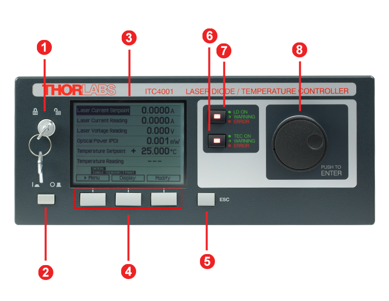
ITC4000 Series Front Panel
| Callout | Connection | Callout | Connection |
|---|---|---|---|
| 1 | Key Switch | 5 | Escape Key |
| 2 | Supply Power Switch | 6 | TEC Status Indicator |
| 3 | LC Display | 7 | LD Status Indicator |
| 4 | Softkeys for Menu Navigation | 8 | Adjustment Knob |
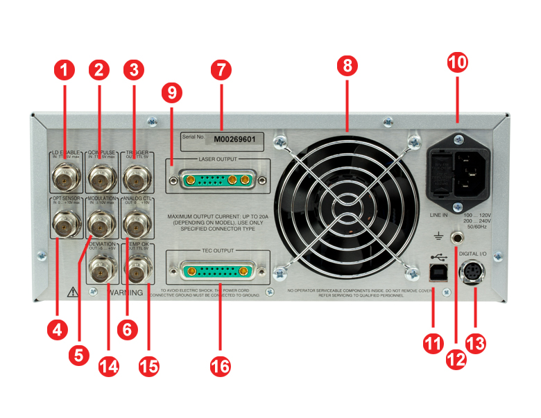
ITC4000 Series Back Panel
| Callout | Connection | Callout | Connection |
|---|---|---|---|
| 1 | TTL Input "Laser Enable In" 5 V Max | 9 | LD Output and Optical Sensor Input "Laser Output" |
| 2 | TTL Input "QCW Pulse In" 5 V Max | 10 | Power Connector and Fuse Holder "Line In" |
| 3 | TTL Output "Trigger Out" 0 - 5 V | 11 | USB Connector |
| 4 | Optical Sensor Input "Opt Sensor In" 0 to 10 V Max |
12 | 4 mm Banana Jack for Chassis Ground |
| 5 | Modulation input "Modulation In" -10 to 10 V |
13 | MiniDin-6 Jack "Digital I/O" |
| 6 | Laser Current Monitor "Analog CTL Out" 0 - 10 V |
14 | Actual Temperature Deviation Output "Deviation Out" -5 to 5 V |
| 7 | Serial Number of the Unit | 15 | TTL Temperature Monitor Output "Temp OK Out" 5 V |
| 8 | Cooling Fan | 16 | TEC Element Output and Temperature Sensor Input "TEC Output" |
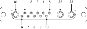
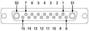
LD Output
13W3 Mixed D-Sub Female
| Pin | Connection | Pin | Connection |
|---|---|---|---|
| 1 | (Thermo) Voltage Sensor Input (+) | 7 | Photo Current Sensor Input (+) |
| 2 | (Thermo) Voltage Sensor Ground (-) | 8 | Photo Current Sensor Ground (-) |
| 3 | Not Connected | 9 | Not Connected |
| 4 | Laser Diode Anode (+) | 10 | Laser Diode Cathode (-) |
| 5 | Output for Interlock and Status Indicator "LASER ON/OFF" (+) | A1 | Laser Diode Ground |
| 6 | Ground Pin for Interlock and Status Indicator "LASER ON/OFF" (-) |
A2 | Laser Diode Cathode (with Polarity AG) (-) |
| A3 | Laser Diode Anode (with Polarity CG) (+) |
TEC Output
17W2 Mixed D-Sub Female
| Pin | Connection | Pin | Connection |
|---|---|---|---|
| 1 | Interlock, TEC ON LED (+) | 10 | PT100/1000 (-), AD590/592 (-), LM35 Out, LM135/235/335 (+) |
| 2 | Voltage Measurement TEC Element (+) | 11 | PT100/1000 (+), AD590/592 (+), LM35/135/235/335 (+) |
| 3 | Thermistor (-), PT100/1000 (-), Analog Ground | 12 | Analog Ground, LM35/135/235/335 (-) |
| 4 | Thermistor (+), PT100/1000 (+) | 13 | Not Connected |
| 5 | Analog Ground, LM35/135/235/335 (-) | 14 | I/O 1-wire (Currently Not Used) |
| 6 | Digital Ground for I/O 1-Wire | 15 | Ground for 12 V Output and Interlock, TEC ON LED (-) |
| 7 | 12 V Output (for External Fan, Max. Current = 500 mA) | S1 | TEC Element (+) (Peltier Element) |
| 8 | Not Connected | S2 | TEC Element (-) (Peltier Element) |
| 9 | Voltage Measurement TEC Element (-) |
Digital I/O Ports
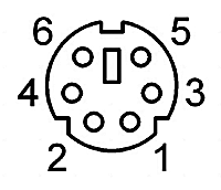
| Pin | Connection |
|---|---|
| 1 | I/O 1 |
| 2 | I/O 2 |
| 3 | I/O 3 |
| 4 | I/O 4 |
| 5 | GND |
| 6 | I/O Supply Voltage (+12 V from Internal or Higher External Voltage up to +24 V) |
LD Enable In
BNC Female
Laser Enable Input (High to Enable Laser ON), TTL 5 V Max
QCW Pulse In
BNC Female
Input for External Trigger Signal, TTL 5 V Max
Trigger Out
BNC Female
QCW Pulse Tracking Output, TTL 5 V
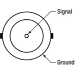
OPT Sensor In
BNC Female
Input for Optical Sensor, 0 to +10 V Max
Modulation In
BNC Female
Input for External Modulation Signal, -10 to +10 V Max
Analog CTL Out
BNC Female
Output for Laser Current Monitoring, 0 to +10 V
Deviation Out
BNC Female
Actual Temperature Deviation Output, -5 to +5 V
Temp OK Out
BNC Female
Temperature OK Output (High if Inside Temperature Window), TTL 5 V
Computer Connection
USB Type B
USB Type B to Type A Cable Included
Ground

4 mm Banana Jack for Chassis Ground
CAB4005 Laser Diode Cable
This cable contains a DB-9 male connector on one side and a 13W3 male connector on the other side. Both views shown below are looking into the connector.
DB-9 Male Connector
| Pin | Color |
| 1 | White |
| 2 | Gray and Pink |
| 3 | Gray / Blacka |
| 4 | Red and Blue |
| 5 | Brown |
| 6 | Blue |
| 7 | Yellow / Purplea |
| 8 | Green / Pinka |
| 9 | Red |
13W3 Male Connector
| 13W3 Connector Colors | |||
|---|---|---|---|
| Pin | Color | Pin | Color |
| 1 | No Connection | 9 | No Connection |
| 2 | No Connection | 10 | Blue |
| 3 | No Connection | A1 | Gray / Blacka |
| 4 | Red | ||
| 5 | White | A2 | Yellow / Purplea |
| 6 | Brown | ||
| 7 | Red and Blue | A3 | Green / Pinka |
| 8 | Gray and Pink | ||
| Pin Matching | ||
|---|---|---|
| DB-9 Pin | 13W3 Pin | Description of ITC Functionality |
| 1 | 5 | Output for Interlock and Status Indicator "LASER ON/OFF" (+) |
| 2 | 8 | Photo Current Sensor Ground (-) |
| 3 | A1 | Laser Diode Ground |
| 4 | 7 | Photo Current Sensor Input (+) |
| 5 | 6 | Ground Pin for Interlock and Status Indicator "LASER ON/OFF" (-) |
| 6 | 10 | Laser Diode Cathode (-) |
| 7 | A2 | Laser Diode Cathode (with Polarity AG) (-) |
| 8 | A3 | Laser Diode Anode (with Polarity CG) (+) |
| 9 | 4 | Laser Diode Anode (+) |
| Shield | Shield | - |
CAB4000 TEC Element Cable
This cable contains a DB-9 female connector on one side and a 17W2 male connector on the other side. Both views shown below are looking into the connector.
DB-9 Female Connector
17W2 Male Connector
| DB-9 Connector Colors | |
|---|---|
| Pin | Color |
| 1 | White |
| 2 | Pink and Gray |
| 3 | Red and Blue |
| 4 | Pink / Red / Purple (3 Wires) |
| 5 | Black / Gray / Blue (3 Wires) |
| 6 | No Connection |
| 7 | Yellow |
| 8 | Brown |
| 9 | Green |
| 17W2 Connector Colors | |||
|---|---|---|---|
| Pin | Color | Pin | Color |
| 1 | White | 11 | Green |
| 2 | Red | 12 | Brown |
| 3 | Red and Blue | 13 | No Connection |
| 4 | Pink and Gray | 14 | No Connection |
| 5 | Brown | 15 | White |
| 6 | No Connection | S1 | Purple / Pink (2 Wires) |
| 7 | No Connection | ||
| 8 | No Connection | S2 | Black / Gray (2 Wires) |
| 9 | Blue | ||
| 10 | Yellow | ||
| Pin Matching | ||
|---|---|---|
| DB-9 Pin | 17W2 Pin(s) | Description of ITC Functionality |
| 1 | 1 | Interlock, TEC ON LED (+) |
| 15 | Ground for 12 V Output and Interlock, TEC ON LED (-) | |
| 2 | 4 | Thermistor (+), PT100/1000 (+) |
| 3 | 3 | Thermistor (-), PT100/1000 (-), Analog Ground |
| 4 | 2 | Voltage Measurement TEC Element (+) |
| S1 | TEC Element (+) (Peltier Element) | |
| 5 | 9 | Voltage Measurement TEC Element (-) |
| S2 | TEC Element (-) (Peltier Element) | |
| 6 | No Connection | - |
| 7 | 10 | PT100/1000 (-), AD590/592 (-), LM35 Out, LM135/235/335 (+) |
| 8 | 5 | Analog Ground, LM35/135/235/335 (-) |
| 12 | Analog Ground, LM35/135/235/335 (-) | |
| 9 | 11 | PT100/1000 (+), AD590/592 (+), LM35/135/235/335 (+) |
| Shield | Shield | - |
CAB4007A Laser Diode / TEC Cable
This cable is made of a highly flexible flat cable and contains a 9W4 male connector on one end and 17W2 and 13W3 male connectors on the other end. The CAB4007A is designed for connecting an LCM100(/M) liquid-cooled mount to a Thorlabs ITC400xQCL series controller.

17W2 Male Connector

13W3 Male Connector
9W4 Male Connector
| CAB4007A | ||||
|---|---|---|---|---|
| 9W4 Pin | Signal | 13W3 Pin | 17W2 Pin | Max Current Input |
| A4 | TEC Cathode (-) | No Connection | A2 | 11 A |
| 2 | No Connection | No Connection | No Connection | 5 A |
| A3 | Laser Diode Anode (+) | A3 | No Connection | 11 A |
| 1 | Thermistor (+) | No Connection | 4 | 5 A |
| 3 | Thermistor (-) | No Connection | 3 | 5 A |
| A2 | Laser Diode Cathode (-) | A2 | No Connection | 11A |
| 4 | EEPROM (+) | 3 | No Connection | 5 A |
| 5 | EEPROM (- / Ground) | 9 | No Connection | 5 A |
| A1 | TEC Anode (+) | No Connection | A1 | 11 A |
| No Connection | Laser Driver Interlock | 5, 6 | No Connection | - |
| No Connection | TEC Driver Interlock | No Connection | 1, 15 | - |
CAB4007B Laser Diode / TEC Cable
This cable is made of a highly flexible flat cable and contains a female Flat 10-Pin HHL connector on one end and 17W2 and 13W3 male connectors on the other end. The CAB4007B is designed for connecting any laser with a standard 10-Pin HHL package to a Thorlabs ITC400xQCL series controller.
17W2 Male Connector
13W3 Male Connector
Flat 10-Pin Female Connector
| CAB4007B | ||||
|---|---|---|---|---|
| Flat 10-Pin HHL Connector |
Signal | 13W3 Pin | 17W2 Pin | Max Current Input |
| 1 | TEC Cathode (-) | No Connection | A2 | 10 A |
| 3 | No Connection | No Connection | No Connection | 5 A |
| 4 | Laser Diode Anode (+) | A3 | No Connection | 10 A |
| 5 | Thermistor (+) | No Connection | 4 | 5 A |
| 6 | Thermistor (-) | No Connection | 3 | 5 A |
| 7 | Laser Diode Cathode (-) | A2 | No Connection | 10 A |
| 8 | EEPROM (+) | 3 | No Connection | 5 A |
| 9 | EEPROM (- / Ground) | 9 | No Connection | 5 A |
| 10 | TEC Anode (+) | No Connection | A1 | 10 A |
| No Connection | Laser Driver Interlock | 5, 6 | No Connection | - |
| No connection | TEC Driver Interlock | No Connection | 1, 15 | - |
Sample Screens of the ITC4000 Series
| Measurement Screen 1 | Measurement Screen 2 | ||
|---|---|---|---|
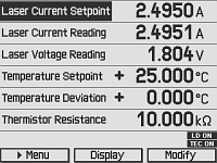 |
The measurement screen offers easy readout of measurement values and device status information. It also allows the major instrument setpoints to be adjusted. You can freely select two, four, or six values to be displayed with optimized character size. | 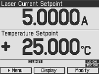 |
Here the measurement screen is configured to 2 values. The character size is enlarged as much as possible for easier reading. |
| Menu Screen | QCW Settings Screen | ||
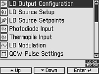 |
The menu screen allows various operation modes and options to be selected. | 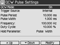 |
This is the input screen for the Quasi-Continuous Wave (QCW) pulse mode settings, e.g. trigger source and pulse parameters. |
| Laser Diode Setup Screen | Photodiode Input Screen | ||
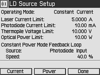 |
The laser diode setup screen allows the user to enter essential laser control parameters: constant current or constant power mode, limits for laser current and laser power, speed and source of the constant power feedback loop. |
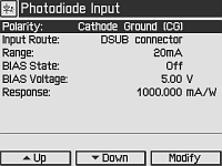 |
All parameters concerning the photodiode sensor are entered via the Photodiode Input Screen. |
| Temperature Controller Screen | Temperature Mode Settings Screen | ||
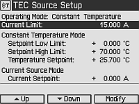 |
All parameters for the temperature controller are entered via the Temperature Controller Screen: Operation Mode, Current Limit, Current Control Mode Settings, Temperature Sensor Settings. | 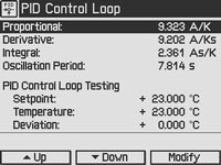 |
For manual optimization, the temperature PID control loop settings can be entered here. Temperature setpoint and actual reading are accessible for convenient testing. |
| PID Auto-Tune Screen | Preferences Screen | ||
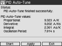 |
The PID auto-tune function is started via this screen. The ITC4000 automatically selects the optimal PID parameters for the current thermal setup. | 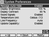 |
The preferences screen offers access to the device preferences, e.g. display and signal settings. |
Software for Laser Diode Controllers
The download button below links to VISA VXI pnp™, MS Visual Studio™, MS Visual Studio.net™, LabVIEW™, and LabWindows/CVI™ drivers, firmware, utilities, and support documentation for Thorlabs' ITC4000 Series laser controllers, LDC4000 Series laser controllers, CLD1000 Series compact laser diode controllers, and TED4000 Series TEC controllers.
The software download page also offers programming reference notes for interfacing with compatible controllers using SCPI, LabVIEW, Visual C++, Visual C#, and Visual Basic. Please see the Programming Reference tab on the software download page for more information and download links.
Driver Software
Version 3.1.0 (April 11, 2014)
Programming Reference
Version 3.3 (April 8, 2015) - SCPI Commands
Version 1.0 (June 16, 2015) - LabVIEW, Visual C++, Visual C#, Visual Basic
The software packages support LabVIEW 8.5 and higher. If you are using an earlier version of LabVIEW, please contact Tech Support for assistance.
| Item # | ITC4001 | ITC4002QCL | ITC4005 | ITC4005QCL | ITC4020 |
|---|---|---|---|---|---|
| Components | |||||
| Benchtop Laser Diode/TEC Controller, 1 A / 96 W | - | - | - | - | |
| Benchtop Laser Diode/TEC Controller, 2 A / 225 W with 17 V Compliance for QCLs | - | - | - | ||
| Benchtop Laser Diode/TEC Controller, 5 A / 225 W | - | - | - | - | |
| Benchtop Laser Diode/TEC Controller, 5 A / 225 W with 20 V Compliance for QCLs | - | - | - | - | |
| Benchtop Laser Diode/TEC Controller, 20 A / 225 W | - | - | - | - | |
| Cable TED4000/ITC4000 to Laser Mount, 5 A, 17W2, D-Sub-9 (CAB4000) | - | ||||
| Cable TED4000/ITC4000 to Laser Mount, 20 A, 17W2, 17W2 (CAB4001) | - | - | - | - | |
| Cable LDC4000/ITC4000 to Laser Mount, 5 A, 13W3, D-Sub-9 (CAB4005) | - | ||||
| Cable LDC4000/ITC4000 to Laser Mount, 20 A, 13W3, 13W3 (CAB4006) | - | - | - | - | |
| Mixed D-Sub Connector, 17W2, Male & Female with 2 High-Current Contacts Each, 20 A (CON4001) |
|||||
| Mixed D-Sub Connector, 13W3, Male & Female with 3 High-Current Contacts Each, 20 A (CON4005) |
|||||
| USB Cable A-B, 2 m | |||||
| 4000 Series Instrumentation CD | |||||
| ITC4000 Series Printed Operation Manual | |||||
| Certificate of Calibration | |||||
PID Basics
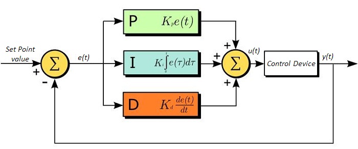
The PID circuit is often utilized as a control loop feedback controller and is very commonly used for many forms of servo circuits. The letters making up the acronym PID correspond to Proportional (P), Integral (I), and Derivative (D), which represents the three control settings of a PID circuit. The purpose of any servo circuit is to hold the system at a predetermined value (set point) for long periods of time. The PID circuit actively controls the system so as to hold it at the set point by generating an error signal that is essentially the difference between the set point and the current value. The three controls relate to the time-dependent error signal; at its simplest, this can be thought of as follows: Proportional is dependent upon the present error, Integral is dependent upon the accumulation of past error, and Derivative is the prediction of future error. The results of each of the controls are then fed into a weighted sum, which then adjusts the output of the circuit, u(t). This output is fed into a control device, its value is fed back into the circuit, and the process is allowed to actively stabilize the circuit’s output to reach and hold at the set point value. The block diagram below illustrates very simply the action of a PID circuit. One or more of the controls can be utilized in any servo circuit depending on system demand and requirement (i.e., P, I, PI, PD, or PID).
Through proper setting of the controls in a PID circuit, relatively quick response with minimal overshoot (passing the set point value) and ringing (oscillation about the set point value) can be achieved. Let’s take as an example a temperature servo, such as that for temperature stabilization of a laser diode. The PID circuit will ultimately servo the current to a Thermo Electric Cooler (TEC) (often times through control of the gate voltage on an FET). Under this example, the current is referred to as the Manipulated Variable (MV). A thermistor is used to monitor the temperature of the laser diode, and the voltage over the thermistor is used as the Process Variable (PV). The Set Point (SP) voltage is set to correspond to the desired temperature. The error signal, e(t), is then just the difference between the SP and PV. A PID controller will generate the error signal and then change the MV to reach the desired result. If, for instance, e(t) states that the laser diode is too hot, the circuit will allow more current to flow through the TEC (proportional control). Since proportional control is proportional to e(t), it may not cool the laser diode quickly enough. In that event, the circuit will further increase the amount of current through the TEC (integral control) by looking at the previous errors and adjusting the output in order to reach the desired value. As the SP is reached [e(t) approaches zero], the circuit will decrease the current through the TEC in anticipation of reaching the SP (derivative control).
Please note that a PID circuit will not guarantee optimal control. Improper setting of the PID controls can cause the circuit to oscillate significantly and lead to instability in control. It is up to the user to properly adjust the PID gains to ensure proper performance.
PID Theory
The output of the PID control circuit, u(t), is given as
where
Kp= Proportional Gain
Ki = Integral Gain
Kd = Derivative Gain
e(t) = SP - PV(t)
From here we can define the control units through their mathematical definition and discuss each in a little more detail. Proportional control is proportional to the error signal; as such, it is a direct response to the error signal generated by the circuit:
Larger proportional gain results is larger changes in response to the error, and thus affects the speed at which the controller can respond to changes in the system. While a high proportional gain can cause a circuit to respond swiftly, too high a value can cause oscillations about the SP value. Too low a value and the circuit cannot efficiently respond to changes in the system.
Integral control goes a step further than proportional gain, as it is proportional to not just the magnitude of the error signal but also the duration of the error.
Integral control is highly effective at increasing the response time of a circuit along with eliminating the steady-state error associated with purely proportional control. In essence integral control sums over the previous error, which was not corrected, and then multiplies that error by Ki to produce the integral response. Thus, for even small sustained error, a large aggregated integral response can be realized. However, due to the fast response of integral control, high gain values can cause significant overshoot of the SP value and lead to oscillation and instability. Too low and the circuit will be significantly slower in responding to changes in the system.
Derivative control attempts to reduce the overshoot and ringing potential from proportional and integral control. It determines how quickly the circuit is changing over time (by looking at the derivative of the error signal) and multiplies it by Kd to produce the derivative response.
Unlike proportional and integral control, derivative control will slow the response of the circuit. In doing so, it is able to partially compensate for the overshoot as well as damp out any oscillations caused by integral and proportional control. High gain values cause the circuit to respond very slowly and can leave one susceptible to noise and high frequency oscillation (as the circuit becomes too slow to respond quickly). Too low and the circuit is prone to overshooting the SP value. However, in some cases overshooting the SP value by any significant amount must be avoided and thus a higher derivative gain (along with lower proportional gain) can be used. The chart below explains the effects of increasing the gain of any one of the parameters independently.
| Parameter Increased | Rise Time | Overshoot | Settling Time | Steady-State Error | Stability |
|---|---|---|---|---|---|
| Kp | Decrease | Increase | Small Change | Decrease | Degrade |
| Ki | Decrease | Increase | Increase | Decrease Significantly | Degrade |
| Kd | Minor Decrease | Minor Decrease | Minor Decrease | No Effect | Improve (for small Kd) |
Tuning
In general the gains of P, I, and D will need to be adjusted by the user in order to best servo the system. While there is not a static set of rules for what the values should be for any specific system, following the general procedures should help in tuning a circuit to match one’s system and environment. In general a PID circuit will typically overshoot the SP value slightly and then quickly damp out to reach the SP value.
Manual tuning of the gain settings is the simplest method for setting the PID controls. However, this procedure is done actively (the PID controller turned on and properly attached to the system) and requires some amount of experience to fully integrate. To tune your PID controller manually, first the integral and derivative gains are set to zero. Increase the proportional gain until you observe oscillation in the output. Your proportional gain should then be set to roughly half this value. After the proportional gain is set, increase the integral gain until any offset is corrected for on a time scale appropriate for your system. If you increase this gain too much, you will observe significant overshoot of the SP value and instability in the circuit. Once the integral gain is set, the derivative gain can then be increased. Derivative gain will reduce overshoot and damp the system quickly to the SP value. If you increase the derivative gain too much, you will see large overshoot (due to the circuit being too slow to respond). By playing with the gain settings, you can maximize the performance of your PID circuit, resulting in a circuit that quickly responds to changes in the system and effectively damps out oscillation about the SP value.
| Control Type | Kp | Ki | Kd |
|---|---|---|---|
| P | 0.50 Ku | - | - |
| PI | 0.45 Ku | 1.2 Kp/Pu | - |
| PID | 0.60 Ku | 2 Kp/Pu | KpPu/8 |
While manual tuning can be very effective at setting a PID circuit for your specific system, it does require some amount of experience and understanding of PID circuits and response. The Ziegler-Nichols method for PID tuning offers a bit more structured guide to setting PID values. Again, you’ll want to set the integral and derivative gain to zero. Increase the proportional gain until the circuit starts to oscillate. We will call this gain level Ku. The oscillation will have a period of Pu. Gains are for various control circuits are then given below in the chart.
| Posted Comments: | |
user
(posted 2023-09-11 15:23:31.14) Hello,
It seems the minimum pulse length for both QCW operation and LD modulation of ITC 4005 controller is 100us. So I want to check whether it is possible to achieve a laser pulse shorter than 100us (for example, ~1us) with an external current pulse generator triggering the ITC 4005? dpossin
(posted 2023-09-19 05:30:57.0) Dear Yang,
Thank you for your feedback. In case you use the external modulation input for generating the QCW signal the pulse lenght can be reduced down to about 30µs when the pulse shape still should be rectangle.
I am reaching out to you to further discuss this matter. user
(posted 2023-03-01 20:21:47.04) Hello,
We are using ITC4001 LD controller to test for an SOA (SOA1013SXS). We had ensured that the recommended setting is chosen for the operation, and when operated, we are getting an error message- 'LD output protection voltage was tripped'. Please help us in bypassing the error message and test for the functionality of SOA. thanks. mdiekmann
(posted 2023-03-07 04:59:57.0) Thank you for contacting us! We will reach out to you directly to troubleshoot. sungtae park
(posted 2022-09-21 18:20:40.187) I am a customer who has written the inquiry below. I'm sorry, but there is a correction, so I'm writing it again. we are using ITC 4020 in our lab. We plan to replace the higher power LD. However, the typical specification of the LD to be replaced is 12A, 10.5V ~ 11.2V. I wonder if the LD to be replaced in the ITC 4020 works normally. wskopalik
(posted 2022-09-21 11:21:35.0) Thank you very much for your feedback!
The ITC4020 can output a laser diode current between 0 – 20 A. So the current requirements of the new diode are fine. The compliance voltage of the ITC4020 is however only 11 V, i.e. 10.5V ~ 11.2V are close or even above the limit. So you might need to reduce the current through the diode a bit to stay below the compliance voltage limit.
I will contact you directly to provide further assistance. sungtae park
(posted 2022-09-21 18:11:41.453) Hi, we are using ITC 4020 in our lab. We plan to replace the higher power LD. However, the typical specification of the LD to be replaced is 20A, 10.5V ~ 11.2V. I wonder if the LD to be replaced in the ITC 4020 works normally. wskopalik
(posted 2022-09-21 11:22:00.0) Thank you very much for your feedback!
The ITC4020 can output a laser diode current between 0 – 20 A. So the current requirements of the new diode are fine. The compliance voltage of the ITC4020 is however only 11 V, i.e. 10.5V ~ 11.2V are close or even above the limit. So you might need to reduce the current through the diode a bit to stay below the compliance voltage limit.
I will contact you directly to provide further assistance. 锋涛 王
(posted 2022-03-21 20:58:03.83) 你好:我们在使用ITC4005作为温度控制器时,开机一直显示Cable和T prot两个标识,TEC无法工作,显示TEC cable connection failure,这个可能是什么原因造成的呢?我们尝试了好多次,至今不能正常工作。谢谢 Aliya Nurmukhanbetova
(posted 2021-08-19 17:53:57.34) Hi! We have an ITC4001 in our lab, and used LDM9LP mount, connected trough CAB4005 cable. I have a problem with LED output. The LED signal is flashing. We tried to test LP450-SF15 laser, we set the following parameters: LD output configuration- >Anode ground, LD source setup-> Laser current limit=110mA; Operation mode=Constant current; and changed the laser current in LD Source Setpoint.
Is therefore something wrong with ITC4001 LD controller? Could you give me recommendations how to run LD output? Best regards, Aliya MKiess
(posted 2021-08-23 07:44:59.0) Dear Aliya, thank you very much for your inquiry. If the green LED on the case is flashing, it may mean the following errors:
-Switch On Delay active
-I-Limit / P-Limit
-Inhibit Input Mode (Output Enable) active
-Temp. Protection Mode (Output Enable) active
If you do not have a temperature controller connected, you must set the Temp. protection mode to "None" in the laser output configurations. For further details and troubleshooting please contact our technical support. L T
(posted 2021-07-16 17:20:10.64) Hi.
We have an ITC4001 in our lab, used in combination with a TCLDM9 mount, connected through CAB4005 and CAB4000 cables. The TEC works fine. However, I have encountered a problem when turning on the LD output. A Laser Current Reading of -0.0001A is shown when the LD is not on. After switching on, the LD produces intermittent output bursts and blinks in irregular pulses. The I LIMIT warning is shown and the green "LD ON" LED flashes even though the Laser Current Setpoint is set well below the Laser Current Limit.
I double checked to ensure that the polarities are set correctly and the LD pins are connected properly, the LD Modulation and QCW Pulse settings are both off, all the operation limits are set according to specifications of the LD. Switching to a different LD, the same problem remains, as it does with a different TCLDM9 mount. It is therefore suspected that there is something wrong with the ITC4001 LD controller.
Could you please give some advises as to the possible reasons for such an error? MKiess
(posted 2021-07-21 10:13:19.0) Thank you very much for your inquiry.I have contacted you directly to help with further troubleshooting and to find an explanation for this phenomenon. WooJin Jeong
(posted 2021-02-22 14:10:49.583) Hi.
How about is rising & falling time for ITC4005?
I can not check your specification & manual.
Please, let me know your specification.
Best regards,
WooJin Jeong MKiess
(posted 2021-02-23 10:14:14.0) Thank you for contacting us. It depends on how you want to modulate the light source. Possibilities are to use the internal modulation of the controller or to realize a modulation via the external modulation input. An estimation of the rise time can be done via the relation 0.35/bandwidth. Under the following link you can find more details regarding this relation:
https://www.thorlabs.de/newgrouppage9.cfm?objectgroup_id=9817
I have contacted you directly to discuss further details. Sarmishtha Satpathy
(posted 2021-02-02 18:50:32.347) There should be a straightforward way to read out the monitor photodiode from the laser packages - either current or the optical power, directly from the driver (ITC4001) to enable safety circuits.
If there is a way to read this current/voltage (from the monitor photodiode), please let me know. dpossin
(posted 2021-02-03 08:18:04.0) Dear Sam,
Thank you for your feedback. Yes there is a way to measure the photodiode current and voltage via SCPI commands. The list of commands can be downloaded here: https://www.thorlabs.com/software/MUC/4000_Series/Manual/Series4000_SPCI_Programmers_Reference_V3.3.pdf
On page 19 there the related commands can be found (:CURRent2[:DC]?). I am reaching out to you in order to provide further support. user
(posted 2020-10-27 16:23:44.923) I have ITC4005 LDs controler in my lab.
Could you recommend any compatible 14-pin DIL Laser Diode Mount ? wskopalik
(posted 2020-10-28 10:40:19.0) Thank you very much for your feedback!
Unfortunately, we do not offer any laser diode mounts for 14-pin DIL packages. The ITC4005 can however be used with third-party mounts as well. The two connector kits CON4001 and CON4005 are included with all ITC4000 devices. They can be used to make custom cables for the connection of the laser diode and the TEC with any mount.
As you have left no contact data, please feel free to contact us at europe@thorlabs.com for further questions. Andrew Devine
(posted 2020-10-09 11:03:04.067) Hello,
Do you plan to offer any models with a higher maximum current than 20 A? We like to use this model for our single emitter type diode testing, but our newer high power products are starting to push 40 A + and we have had to look for higher power alternatives.
Thanks,
Andrew Devine nreusch
(posted 2020-10-16 03:07:27.0) Thank you for contacting us and for sharing your need for drivers with higher currents. Unfortunately, we do not have any concrete plans to offer such drivers in the near future. CS Wen
(posted 2019-12-26 02:31:05.423) Dear Thorlabs, I have some problems with monitor opt sensor. I connected the PDA50B output voltage via a BNC cable to the ITC4020 R4 "OPT sensor in". The thermopile voltage reading will be lower (10% off) if the LD operates in QCW mode with the pulse width of 100us. the voltage will recover to the normal level if i enlarge the pulse width above 250us.
however, i replaced the PDA50B by a general PD with current output connected to the R4 and set the ITC4020 to read the PD current. that will be the same PD current value no matter how short is the pulse width i've set.
could it be the reason of different sampling method between voltage and current sensor type.
and how coudl i got the correct thermopile voltage under QCW operation? thank you. MKiess
(posted 2020-01-02 07:13:09.0) This is a response from Michael at Thorlabs. Thank you for the inquiry. I have contacted you directly to discuss all details of this case with you. Ben Dumaguing
(posted 2019-11-28 21:24:49.37) Hello, I have a problem on LD, the warning indicator is blinking green. What does it mean. How can I correct the problem. Thank you MKiess
(posted 2019-12-02 06:35:48.0) This is a response from Michael at Thorlabs. Thank you for the inquiry. If this LED flashes, there may be several reasons for this. While this LED is flashing, the LD Output is switched off. The flashing occurs when the switch on Delay is still active, the set current or power limits have been reached, you set the Inhibit Input Mode, to output enable and an error occurs, or if you set Temperature Protection Mode to Ouptut Enable and the temperature is outside the selected temperature window of your system.
All parameters related to these settings can be set in the Laser Output Configurations of the controller. I have contacted you directly for further assistance. Ben Dumaguing
(posted 2019-11-28 20:55:50.553) Hello, I have a problem on LD, the warning indicator is blinking green. What does it mean? ali.ab.salman
(posted 2019-01-09 04:35:08.07) Dear Thorlabs, We have ITC4020 in our lab. Recently the adjustment knob to change set values is hardly moving and can not be pushed to enter any value.
Please suggest any solution as soon as possible.
Regards swick
(posted 2019-01-11 04:43:29.0) This is a response from Sebastian at Thorlabs. Thank you for the inquiry.
Your explanation indicates the ITC4020 has defective rotating knob.
Before sending the device in for repair work-around would be to control the ITC4020 via remote.
I contacted you directly to provide assistance. ikucukkara
(posted 2018-07-29 23:09:02.803) Dear Thorlabs,
I plan to buy a ITC4020. I want to make sure that temperature control range in between -150 Celius and plus +200 Celcius for PT100.
Is there any a temperature sensor you suggest working with ITC4020 in this range.
I have found PT100 does it suit?
https://uk.rs-online.com/web/p/platinum-resistance-temperature-sensors/6117794/ wskopalik
(posted 2018-08-02 02:25:37.0) This is a response from Wolfgang at Thorlabs. Thank you very much for your feedback!
The ITC4000 controller series supports different types of temperature sensors, but unfortunately the complete range of -150°C to +200°C is not covered by any of them. E.g. in the case of a PT100 sensor, the resistance of the PT100 changes as a function of the temperature and the controller can only measure these changes accurately within a range of -55°C to +150°C.
I will however see if we can offer a custom version of this controller and will contact you directly. ikucukkara
(posted 2018-07-25 03:26:16.523) https://www.thorlabs.com/newgrouppage9.cfm?objectgroup_id=4052
Is there any a temperature sensor you suggest working with ITC4020 in the range between minus 150C and plus 200C?
I have found PT100 does it suit?
https://uk.rs-online.com/web/p/platinum-resistance-temperature-sensors/6117794/ wskopalik
(posted 2018-08-02 02:43:10.0) This is a response from Wolfgang at Thorlabs. Thank you very much for your feedback! Please find my answer in the feedback above. hoyapeter
(posted 2018-04-01 01:59:54.53) Hello. I have some problem of the "PD Current Reading". This time use the LD specification is typically [ Laser Power 70mW , Operation Current 100mA and then Monitoring Output Current 0.25mA ] , but not increase the "PD Current reading data. The value is 0.0438 mA or more dose not rise.
It is why ? and how to do that ? Please feed back with rapdly. swick
(posted 2018-04-11 04:46:13.0) This is a response from Sebastian at Thorlabs. Thank you for the inquiry. I contacted you directly for troubleshooting. timflywind
(posted 2018-01-22 18:45:42.38) Hello, I have updated ITC4005 firmware from v1.4.0 to v1.8.0. The function of Support for LD output noise reduction filter added is in v1.5.0, but when I update to v1.8.0. This function isn't display in LD Output Configuration. How can I get this function? swick
(posted 2018-01-24 03:50:22.0) This is a response from Sebastian at Thorlabs. Thank you for the inquiry. The noise reduction filter was implemented begin of 2013. The switchable filter used for noise reduction is not embedded for devices manufactured before 2013. I contacted you directly for further assistance. dmitry.busko
(posted 2017-07-03 11:48:54.533) Dear Thorlabs Team,
We are using ITC40xx every day and have several questions: 1. is it possible to transfer all settings from "settings memories" to another driver same model? 2. We change the connections from LED to laser and recall settings quite often. As you now - it is quite easy to make a mistake and click "Save settings" instead or "Recall". Is it possible to introduce in a new firmware the "save confirmation" feature?!
3. One small bug I found - after recall of settings TEC does not change the protection mode (setting does, but the new state is not applied). The driver should be restarted or protection mode should be switched Off-On.
Thank you in advance,
Dmitry. swick
(posted 2017-07-07 04:18:50.0) This is a response from Sebastian at Thorlabs. Thank you for the inquiry.
1. At the time it is not planned to add this kind of feature to the ITC-Series. Our engineers will look into this.
2. and 3. We will try to fix this with next firmware update. haferkemper
(posted 2015-07-27 09:07:42.52) Sehr geehrte Damen und Herren,
wir sind ein Unternehmen für lichttechnische Messdienstleistungen und haben schon mehrere Jahre Erfahrung mit Ihren ITC40xx-Produkten. Wir sind wirklich sehr zufrieden mit den Geräten (bisher 3 Stück gekauft beim Fachgebiet Lichttechnik der TU Darmstadt) und nutzen Sie zur Temperierung und dem Betrieb von LEDs. Nun haben wir mittlerweile mehrere größere LED-Module welche eine Vorwärtsspannung bis zu 35V haben. Selbstverständlich haben wir Betriebsgeräte für die Messung dieser Module, jedoch würden wir gern einen Einbrennstand aufbauen, bei dem wir den Betrieb sowie die Temperierung auch über ein ITC lösen möchten. Mit welchem Aufwand wäre es verbunden eine Variante für höhere Spannungen herzustellen, bzw. ab wie vielen Stück wäre dies für Sie interessant?
Ich freue mich auf eine Antwort!
Mit vielen Grüßen,
Nils Haferkemper shallwig
(posted 2015-07-28 04:57:37.0) Sehr geehrter Herr Haferkemper,
vielen Dank für Ihre Anfrage. Leider erlauben unsere momentan für den ITC verfügbaren Schaltungsdesings nur eine maximale compliance Spannung von 20V (ITC4005QCL) und in naher Zukunft ist es uns nicht möglich hier ein Gerät mit höherer Spannung zu entwickeln und anzubieten. In den nächsten Wochen werden wir einen neuen LED Treiber herausbringen der bis zu 50V bei 1A unterstützen wird. Allerdings hat dieser Treiber keine Temperaturkontrolle, diese müsste hier über einen separaten Treiber gelöst werden. Hierfür gäbe es je nach Anforderungen auch separate Treiber von uns: http://www.thorlabs.com/navigation.cfm?guide_id=2107
Ich habe Sie direkt kontaktiert um Ihre Anwendung und weitere Lösungsmöglichkeiten im Detail zu diskutieren.
Viele Grüße
Stefan Hallwig ikucukkara
(posted 2014-10-19 12:02:06.823) I need to know if ITC4000 series controllers can manage (-100 Celcius). Is it posssible a modification to get it from (-55 Celcius to -100 Celcius). shallwig
(posted 2014-10-20 10:12:22.0) This is a response from Stefan at Thorlabs. Thank you very much for your inquiry. The maximum temperature control range dependent on the used sensor is from -55 to +150°C. At the moment we have no sensor which can control down to -100°C. I will contact you directly to discuss your application in detail. helmut.maeckel
(posted 2014-07-11 11:54:33.2) Sehr geehrte Damen und Herren,
ich würde gerne wissen, welche Fall/Rise Zeiten ich mit diesem Laserkontroller bekommen kann. Hängt dies noch von dem Laser ab? Der Laser, den ich gerne benützen möchte, hat die Nummer LP852-SF30.
Mit freundlichen Grüssen,
Helmut Mäckel shallwig
(posted 2014-07-14 05:59:54.0) Sehr geehrter Herr Mäckel,
vielen Dank für Ihre Anfrage im Feedbackformular auf unserer Website. Grundsätzlich wird die Modulationsmöglichkeit auch durch die Laserdiode selbst begrenzt allerdings liegt die Grenze bei dieser Laserdiode im MHz Bereich. Daher limitiert zunächst die Bandbreite des ITC4001 die Modulationsmöglichkeit auf 150 kHz. Der nächst höhere limitierende Faktor wäre noch der Laserdioden Mount wie z.B. der LM9LP für pigtailed Laserdioden http://www.thorlabs.com/newgrouppage9.cfm?objectgroup_id=4839&pn=LM9LP#4839 Dieser begrenzt ebenfalls die maximal mögliche Modulationsgeschwindigkeit im Vergleich zum eigentlichen Limit der Laserdiode.
Ich werde Sie direkt kontaktieren um Ihre Anwendung im Detail zu besprechen.
A response from Stefan at Thorlabs. Thank you very much for your inquiry. In general this laser diode itself is limited to modulations in the MHz range. Therefore the primary limiting factor in this case would be the ITC4001 which allows modulations up to 150 kHZ. The next limiting factor would be the mount, such as the LM9LP http://www.thorlabs.com/newgrouppage9.cfm?objectgroup_id=4839&pn=LM9LP#4839
I will contact you directly to discuss your application in detail. tschalk
(posted 2012-10-23 12:10:00.0) A response form Thomas at Thorlabs: Thank you for your inquiry! The ITC4001 has a USB connection which can be used to remotely program any desired temperature sweep. We offer a full SDK to achieve such tasks which is documented in the programmer's reference manual. While a temperature sweep of 1 s is in principle no problem for the ITC4001, the thermal time constant of the complete system (driver + Pelletier+ holder for the laser diode + diode) might prevent this. This will depend on the available power from the ITC4001, the size and efficiency of the Pelletier element and the mechanical properties of the holder for the laser diode. I will contact you directly to discuss the details of your setup in order to see if the sweep time you need could be achieved with the ITC4001. oscar.esteban
(posted 2012-10-23 10:31:24.257) Dear Thorlabs team,
I'm interested in performing wavelength sweeps thorugh temperature changes. The interest ranges would be about 1 nm with a change rate of about 1s. I know that old modules allowed to do this kind of experiemnts, but I'm not sure how to do with this new one. Is it possible? How?
Thank you very much.
Óscar jvigroux
(posted 2012-07-20 12:28:00.0) A response from Julien at Thorlabs: Thank you for your inquiry. You can control all parameters accessible on the front panel of the device also per USB. We offer a full SDK for the ITC4000 lines. This SDK can be installed with the CD provided with the unit or downloaded from our website under tab software of the ITC4000 product page. The SDK contains all necessary Labview VI's. Those are automatically installed in the instr.lib folder of labview provided a Labview version is already installed. this means that you can access the VI's from the function palette of Labview also. We also provide a Labview example that shows how to communicate with the device. This example can be found after installation of the driver in C:\Program Files\IVI Foundation\VISA\WinNT\TL4000_Drv\Samples\LabVIEW gurakyu
(posted 2012-07-20 15:55:55.0) hi. I have a question about your equipment, ITC4020 model your company provide.
First of all, I want to know if it is possible to control ITC4020 by using USB, and I can get a value of result and temperature control by using Labview program. If possible to get the value, let me know whether you have some program you provide or some sample coded by Labview.
Unless you have it, can you let me exactly know how to connect ITC4020 with Labview and code the program. Thanks. sharrell
(posted 2012-07-19 11:50:00.0) A response from Julien at Thorlabs: Thank you for your inquiry! The ITC4001 has an analog input that can be used to control the laser diode current. This input could be for instance connected to the analog output of your DAQ card directly since it accepts voltages. The resolution achievable in terms of current setting for this input is the same as the resolution specified for the unit, namely 16 µA. The small signal 3 dB bandwidth of the ITC4001 is 100 kHz and will probably the main speed limiting factor in your case. ta_nis80
(posted 2012-07-18 07:46:02.0) Dear Thorlabs Team
Please, I need to confirm some questions about (LASER DIODE AND TEC CONTROLLERS). I plan to design a feedback system to stabilize Laser diode (LD)(CW) with Confocal Fabry Perot Cavity (CFPI)at spectral frequency. I ask about the capability and the method to connect (DAQ-500MHz bandwidth) with (ITC4001)to control the laser diode current to change the spectral frequency. Will I need to voltage current converter and what is the Resolution of driving current? (100 µA ?) – How much is the response time or frequency to control the laser current.
With my best regards
Tamer jvigroux
(posted 2012-04-04 09:09:00.0) A response from Julien at Thorlabs: Thank you for your inquiry! The ITC4001 is a regulated current source, so that the output current is constantly measured and the supplied voltage readjusted based on the last measured current, so that the output current is. Should you use two of those in parallel, the system could become unstable as the interaction between both source currents might lead to one device trying to regulate for the other.
I would strongly recommend using a higher current version of this driver line like for instance the ITC4005. Should you need any further information, please do not hesitate to contact us at techsupport@thorlabs.com. user
(posted 2012-04-04 09:48:39.0) I am interested if two ITC4001 devices can be connected in parallel to achieve higher laser diode current (e.g. 1.5A). Thorlabs
(posted 2010-06-28 09:09:27.0) Response from Javier at Thorlabs to hitech_laserservices: the ITC laser diode and temperature controllers feature internal and external modulation from DC up to 100 kHz (50 kHz for the ITC4020). The internal modulation is programmable through the LD Modulation section of the menu. Also, an external modulation input can be connected at the back of the unit through a BNC connector. Now, in order to modulate the output of the laser up to 300 kHz, you can use the Bias-T input of the LM14S2 temperature controlled butterfly laser diode mount. This input allows for modulation from 200 kHz up to 500 MHz (http://www.thorlabs.com/NewGroupPage9.cfm?ObjectGroup_ID=1558&pn=LM14S2). Keep in mind that the maximum current input allowed by the LM14S2 is 5 A. hitech_laserservices
(posted 2010-06-26 07:32:20.0) Dear Sir,
Please let us know, how could we use these models to drive our fiber laser module in pulsed mode. pulse repetition rate being 30 to 300 kHz. We are developing a ytterbium fiber laser module.
With regards
Ramesh Adam
(posted 2010-03-17 18:14:39.0) A response from Adam at Thorlabs to J.mccord: The LDC40XX and ITC40XX can be used to control LEDs. To answer your question about operating these in pulsed mode, we would need more information. Can you please let us know the repetition rate, pulse width, and cooling requirements. We will email you directly to get all this information. j.mccord
(posted 2010-03-16 14:51:58.0) Hi there,
can this also be used to drive a high power LED in a pulsed mode?
Best regards,
Jeffrey McCord |
Laser Diode Controller Selection Guide
The tables below are designed to give a quick overview of the key specifications for our laser diode controllers and dual diode/temperature controllers. For more details and specifications, or to order a specific item, click on the appropriate item number below.
| Current Controllers | ||||||
|---|---|---|---|---|---|---|
| Item # | Drive Current | Compliance Voltage | Constant Current | Constant Power | Modulation | Package |
| LDC200CV | 20 mA | 6 V | External | Benchtop | ||
| VLDC002 | 25 mA | 5 V | - | Int/Ext | OEM | |
| LDC201CU | 100 mA | 5 V | External | Benchtop | ||
| LD2000R | 100 mA | 3.5 V | - | External | OEM | |
| EK2000 | 100 mA | 3.5 V | - | External | OEM | |
| LDC202C | 200 mA | 10 V | External | Benchtop | ||
| KLD101 | 230 mA | ≤10 V | External | K-Cube™ | ||
| IP250-BV | 250 mA | 8 Va | External | OEM | ||
| LD1100 | 250 mA | 6.5 Va | - | -- | OEM | |
| LD1101 | 250 mA | 6.5 Va | - | -- | OEM | |
| EK1101 | 250 mA | 6.5 Va | - | -- | OEM | |
| EK1102 | 250 mA | 6.5 Va | - | -- | OEM | |
| LD1255R | 250 mA | 3.3 V | - | External | OEM | |
| LDC205C | 500 mA | 10 V | External | Benchtop | ||
| IP500 | 500 mA | 3 V | External | OEM | ||
| LDC210C | 1 A | 10 V | External | Benchtop | ||
| LDC220C | 2 A | 4 V | External | Benchtop | ||
| LD3000R | 2.5 A | -- | - | External | OEM | |
| LDC240C | 4 A | 5 V | External | Benchtop | ||
| LDC4005 | 5 A | 12 V | Int/Ext | Benchtop | ||
| LDC4020 | 20 A | 11 V | Int/Ext | Benchtop | ||
| Dual Temperature and Current Controllers | |||||||
|---|---|---|---|---|---|---|---|
| Item # | Drive Current | Compliance Voltage | TEC Power (Max) | Constant Current | Constant Power | Modulation | Package |
| VITC002 | 25 mA | 5 V | >2 W | - | Int/Ext | OEM | |
| ITC102 | 200 mA | >4 V | 12 W | Ext | OEM | ||
| ITC110 | 1 A | >4 V | 12 W | Ext | OEM | ||
| ITC4001 | 1 A | 11 V | >96 W | Int/Ext | Benchtop | ||
| CLD1010LPa | 1.0 A | >8 V | >14.1 W | Ext | Benchtop | ||
| CLD1011LPb | 1.0 A | >8 V | >14.1 W | Ext | Benchtop | ||
| CLD1015c | 1.5 A | >4 V | >14.1 W | Ext | Benchtop | ||
| ITC4002QCLd | 2 A | 17 V | >225 W | Int/Ext | Benchtop | ||
| ITC133 | 3 A | >4 V | 18 W | Ext | OEM | ||
| ITC4005 | 5 A | 12 V | >225 W | Int/Ext | Benchtop | ||
| ITC4005QCLd | 5 A | 20 V | >225 W | Int/Ext | Benchtop | ||
| ITC4020 | 20 A | 11 V | >225 W | Int/Ext | Benchtop | ||
We also offer a variety of OEM and rack-mounted laser diode current & temperature controllers (OEM Modules, PRO8 Current Control Rack Modules, and PRO8 Current and Temperature Control Rack Modules).
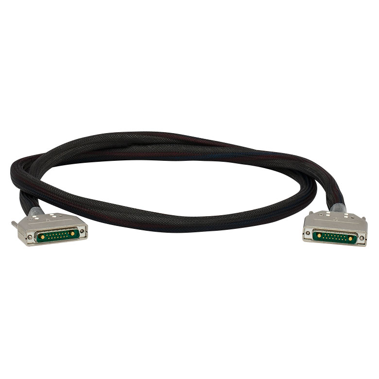
| Item # | CAB4005 | CAB4006 | CON4005 |
|---|---|---|---|
| Click Image to Enlarge | 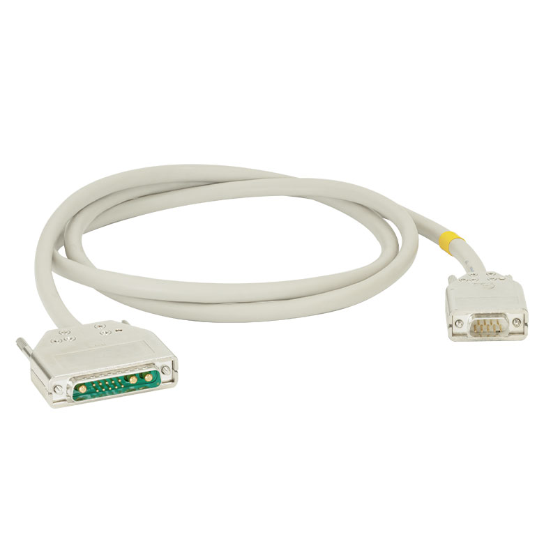 |
 |
 |
| Description | Standard Laser Diode Cable | High Current Laser Diode Cable | 13W3 Male and Female Connector Kit (One Each) |
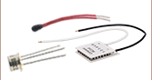
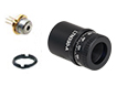
| Max Current | 5 A | 20 A | 20 A |
| Connector Type | 13W3 Male to DB-9 Male | 13W3 Male to 13W3 Male | Loose 13W3 Connectors, Male and Female |
These cables connect our ITC4000 series dual current / temperature controllers or our LDC4000 series current controllers to laser diodes. We also provide loose 13W3 connectors for customers who wish to make their own cables. Please see the Pin Diagrams tab for specific pinout information.
Please note that the CAB4005 cable is included with the purchase of the ITC4001, ITC4002QCL, ITC4005, and ITC4005QCL benchtop controllers. The ITC4020 is shipped with the CAB4006 cable. A CON4005 connector kit is included with all of these benchtop controllers (see the Shipping List tab for details).
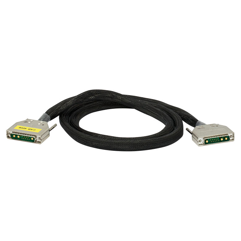
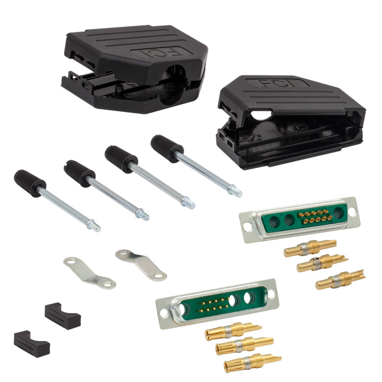
| Item # | CAB4000 | CAB4001 | CON4001 |
|---|---|---|---|
| Click Image to Enlarge | 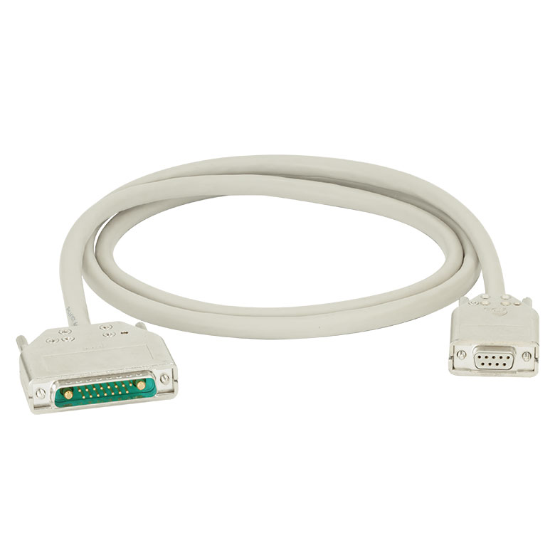 |
 |
 |
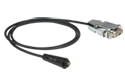
| Description | Standard TEC Element Cable | High Current TEC Element Cable | 17W2 Male and Female Connector Kit (One Each) |
| Max Current | 5 A | 20 A | 20 A |
| Connector Type | 17W2 Male to DB-9 Female | 17W2 Male to 17W2 Male | Loose 17W2 Connectors, Male and Female |
These cables connect our ITC4000 series dual current / temperature controllers or our TED4015 temperature controller to thermoelectric cooling elements. We also provide loose 17W2 connectors for customers who wish to make their own cables. Please see the Pin Diagrams tab for specific pinout information.
Please note that the CAB4000 cable is included with the purchase of the ITC4001, ITC4002QCL, ITC4005, and ITC4005QCL benchtop controllers. The ITC4020 is shipped with the CAB4001. The CON4001 connector kit is included with all of the controllers (see the Shipping List tab for specific details).
| Item # | CAB4007A | CAB4007B | |
|---|---|---|---|
| Click Image to Enlarge |  |
 |
|
| Description | Hi-Flex LD / TEC Cable for LCM100(/M) Mount |
Hi-Flex LD / TEC Cable for 10-Pin HHL Packages |
|
| Max Currenta | Pin A1, A2, A3, A4 | 11 A | 10 A |
| Pin 1, 2, 3, 4, 5 | 5 A | 5 A | |
| Connector Type | 17W2 Male and 13W3 Male to 9W4 Male |
17W2 Male and 13W3 Male to a Flat 10-Pin HHL Female Connector |
|
| Length | 1.5 m | 1.5 m | |
The CAB4007x connector cables for HHL laser packages are Hi-Flex™†, unshielded cables designed for high-current applications, where the laser diode (LD) and thermoelectric cooler (TEC) currents exceed most standard cable limits.
The CAB4007A cable connects the complete LCM100(/M) mount to ITC400xQCL series controllers via the 9W4 connector. The CAB4007B cable can connect any standard 10-Pin HHL laser directly to an ITC400xQCL series controller via the flat 10-Pin HHL female connector. The CAB4007B connector cable can be used with the LCM100(/M) mount when only the top cold plate is in use. For the pinout of the CAB4007A and CAB4007B cables, please see the Pin Diagrams tab.
Please pay attention to the controller specifications when the CAB4007A or CAB4007B connector cables are used with a controller other than the ITC400xQCL controllers to ensure that the cables will safely connect to the controller(s).
†Hi-Flex™ is a Trademark of Cicoil
| Calibration Service Item # | Compatible Controllers |
|---|---|
| CAL-ITC4 | ITC4001, ITC4002QCL, ITC4005, ITC4005QCL, ITC4020 |
Thorlabs offers recalibration services for our ITC4000 Series Combined Laser Diode and TEC Controllers. To ensure accurate measurements, we recommend recalibrating the devices every 24 months. The table to the right lists the controllers for which the CAL-ITC4 recalibration service is available.
Requesting a Calibration
Thorlabs provides two options for requesting a calibration:
- Complete the Returns Material Authorization (RMA) form. When completing the RMA form, please enter your name, contact information, the Part #, and the Serial # of the item being returned for calibration; in the Reason for Return field, select "I would like an item to be calibrated." All other fields are optional. Once the form has been submitted, a member of our RMA team will reach out to provide an RMA Number, return instructions, and to verify billing and payment information.
- Enter the Part # and Serial # of the item that requires recalbration below and then Add to Cart. A member of our RMA team will reach out to coordinate return of the item for calibration. Should you have other items in your cart, note that the calibration request will be split off from your order for RMA processing.
Please Note: To ensure your item being returned for calibration is routed appropriately once it arrives at our facility, please do not ship it prior to being provided an RMA Number and return instructions by a member of our team.