 Products Home / Imaging Systems / OCT Imaging Systems & Components / OCT Components / Scan Lenses for OCT Imaging
Scan Lenses for OCT Imaging

- Optimized for OCT Laser Scanning Systems
- Telecentric Scanning Objectives with a Flat Image Plane
- Minimal Optical Aberrations and Low F-Theta Distortion
- Large Maximum Fields of View up to 28.9 by 28.9 mm2
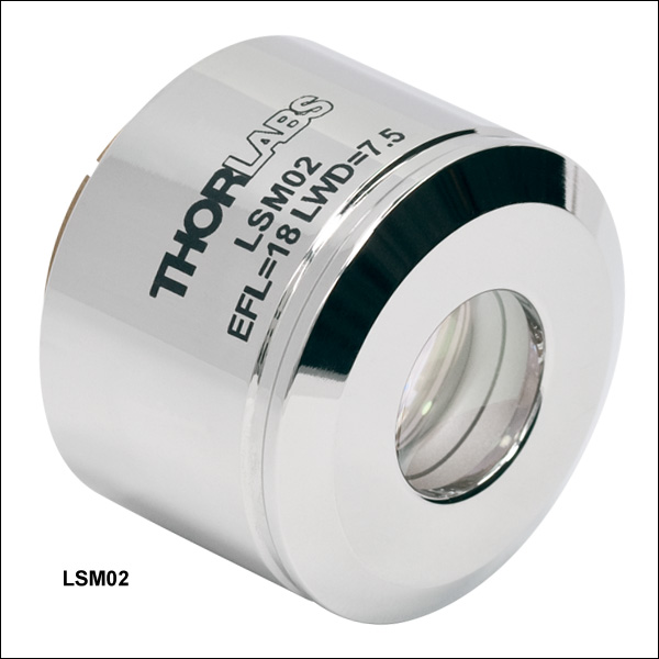
LSM02
1250 to 1380 nm
EFL = 18 mm
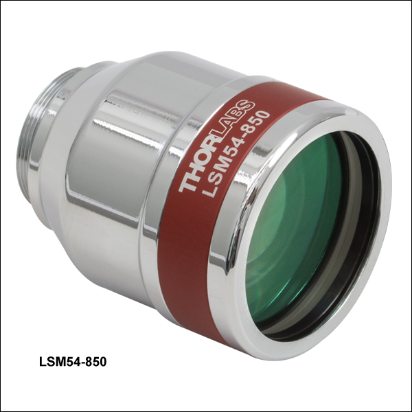
LSM54-850
750 to 950 nm
EFL = 54 mm
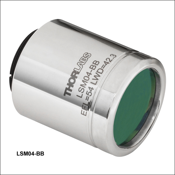
LSM04
1250 to 1380 nm
EFL = 54 mm
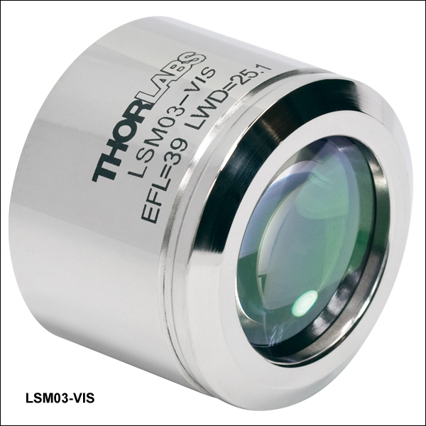
LSM03-VIS
400 to 700 nm
EFL = 39 mm
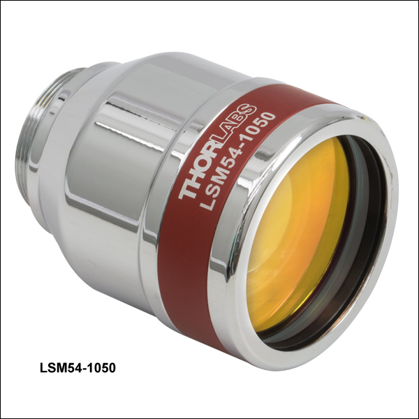
LSM54-1050
950 to 1150 nm
EFL = 54 mm


Please Wait
| Objective Lens Selection Guide |
|---|
| Objectives |
| Microscopy Objectives, Dry Microscopy Objectives, Oil Immersion Physiology Objectives, Water Dipping or Immersion Long Working Distance Objectives Reflective Microscopy Objectives UV Microscopy Objectives 532 nm and 1064 nm Objectives |
| Scan Lenses and Tube Lenses |
| Lenses for OCT Scan Lenses Infinity-Corrected Tube Lens |
 Zemax Files Zemax Files |
|---|
| Click on the red Document icon next to the item numbers below to access the Zemax file download. Our entire Zemax Catalog is also available. |
Features
- Flat Image Plane
- Minimal Optical Aberration Over Image Plane (See Specs Tab for Details)
- Large Field of View
- Low F-Theta Distortion
- Easily Incorporated into Custom-Built Microscopy Systems
- Dispersion Compensators Available Separately for LSM02(-BB), LSM03(-BB), LSM03-VIS, LSM04(-BB), and LSM05(-BB)
| Table 1.1 Scan Lens Quick Links | |
|---|---|
| Wavelength | Item # |
| 400 to 700 nm | LSM03-VIS |
| 750 to 950 nm | LSM54-850 |
| 800 to 1100 nm | LSM02-BB, LSM03-BB, LSM04-BB, and LSM05-BB |
| 950 to 1100 nm | LSM54-1050 |
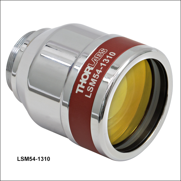
| 1200 to 1400 nm | LSM54-1310 |
| 1250 to 1380 nm | LSM02, LSM03, LSM04, and LSM05 |
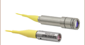
Thorlabs' LSM scan lenses are optimized for Optical Coherence Tomography (OCT) laser scanning imaging systems. Telecentric scan lenses are crucial for OCT and other laser scanning imaging systems, as they produce a flat imaging plane as a laser beam is scanned across the sample. A low f-theta distortion creates geometrically correct scanned images that do not require extensive post-image processing. A telecentric scan lens path can also maximize the captured scattered or emitted light from the sample (the signal) into the detection system. In addition, the spot size and shape vary minimally over the entire FOV (see Specs tab), which results in nearly constant image resolution.
These scan lenses operate over wavelength ranges centered on the popular OCT wavelengths of 633, 850, 1050, or 1315 nm. They offer a selection of effective focal lengths, fields of view, depths of view, and related parameters. All have AR coatings designed to minimize back reflections from broadband light sources.
The LSM02-BB, LSM03-BB, LSM04-BB, and LSM05-BB lenses have been designed to support operation around both 850 and 1050 nm, and therefore several system parameters have been specified (see the Specs tab) at 850 nm and 1050 nm.
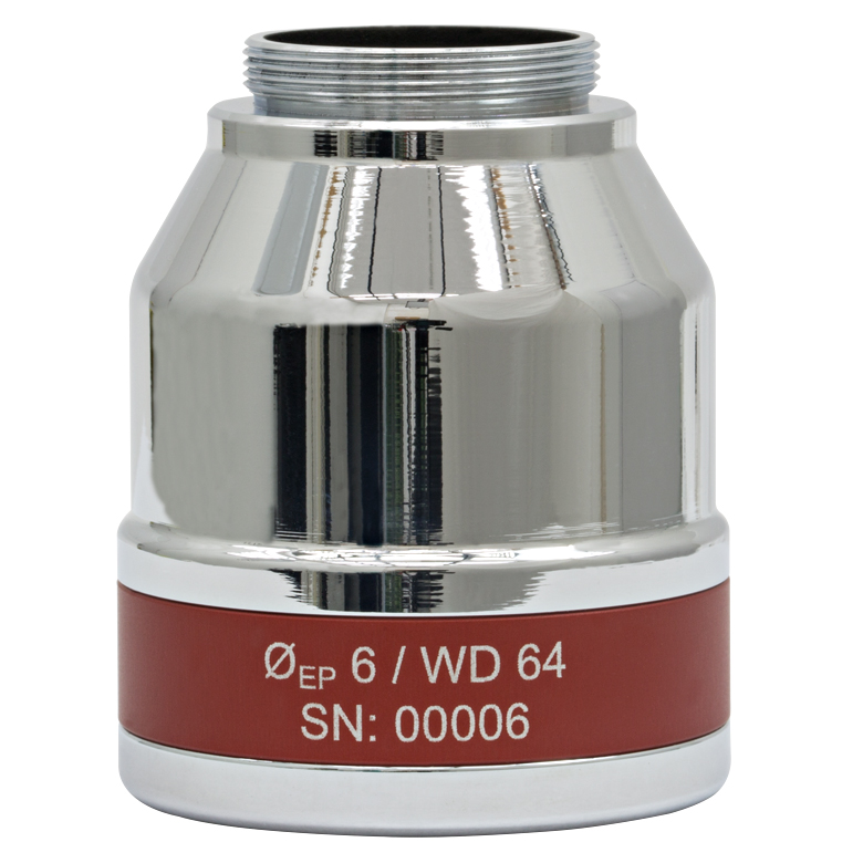
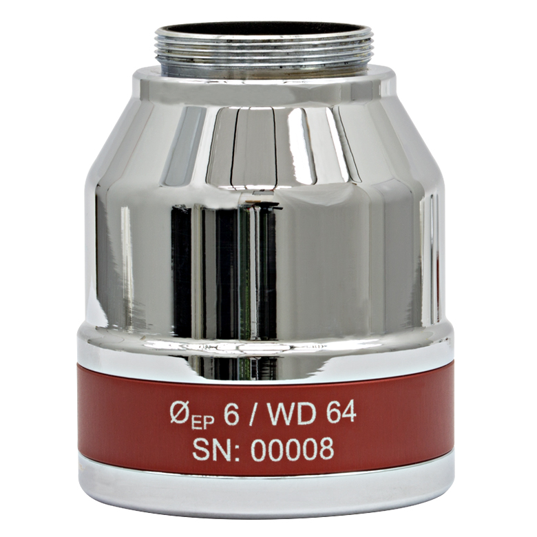
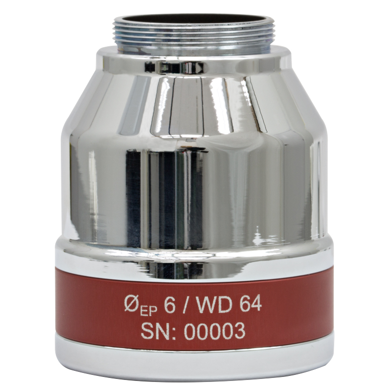
The LSM54-850, LSM54-1050, and LSM-1310 scan lenses are optimized for operation around 850, 1050, and 1300 nm, respectively. Their large 6 mm entrance pupils and ±14° scan angles (single-axis scan) make them ideal for use with larger galvo mirrors that produce more highly deflected beams. The LSM54-850, LSM54-1050, and LSM54-1310 scan lenses have also been optimized to provide a flat field of view, and they are corrected for chromatic aberrations across their wide 200 nm band of operating wavelengths. Please see the Specs tab for detailed information.
Click on the links in Table 1.1 to jump to lenses of interest, or scroll down the page.
Specifications
The complete specifications available for each scan lens are provided in Tables 2.1 and 2.2, and definitions of the various parameters follow the tables. Click the icons, ![]() , to view the plots.
, to view the plots.
| Table 2.1 Lenses with Wavelength Ranges Between 400 and 1150 nm | ||||||||
|---|---|---|---|---|---|---|---|---|
| Item # | LSM03-VIS | LSM54-850 | LSM02-BB | LSM03-BB | LSM04-BB | LSM05-BB | LSM54-1050 | |
| Optical Specifications | ||||||||
| Wavelength Range | 400 to 700 nm | 750 to 950 nm | 800 to 1100 nma | 950 to 1150 nm | ||||
| Effective Focal Length | 39 mm | 54 mm | 18 mm | 36 mm | 54 mm | 110 mm | 54 mm | |
| Entrance Pupil Diameterb | 4 mm | 6 mm | 4 mm | 8 mm | 6 mm | |||
| Parfocal Distance | 50.7 mm | 112 mm | 30.7 mm | 50.5 mm | 80.7 mm | 154.8 mm | 112 mm | |
| Lens Working Distance | 25.1 mm | 64 mm | 7.5 mm | 25.1 mm | 42.3 mm | 93.8 mm | 64 mm | |
| Scanning Distancec | 29.0 mm ± 5 mm | 17.8 mm ± 7.5 mm | 16.1 mm ± 5 mm | 18.9 mm ± 5 mm | 18.9 mm ± 5 mm | 75.5 mm ± 5 mm | 17.8 mm ± 7.5 mm | |
| Optical Scan Angled (Single-Axis Scan) |
Maximum | ±10.6° | ±14.0° | ±10.6° | ±10.6° | ±10.6° | ±10.6° | ±14.0° |
| Diffraction Limited | ±8.4° (543 nm) | ±13.6° | ±10.2° (850 nm) ±10.6° (1050 nm) |
±9.0° (850 nm) ±9.7° (1050 nm) |
±10.6° (850 nm) ±10.6° (1050 nm) |
±7.2° (850 nm) ±8.1° (1050 nm) |
±14.0° | |
| Optical Scan Angled (Two-Axis Scan) |
Maximum | ±7.5° x ±7.5° | ±10.0° x ±10.0° | ±7.5° x ±7.5° | ±7.5° x ±7.5° | ±7.5° x ±7.5° | ±7.5° x ±7.5° | ±10.0° x ±10.0° |
| Diffraction Limited | ±5.1° x ±5.1° (543 nm) |
±8.4° x ±8.4° | ±5.1° x ±5.1° (850 nm) ±5.9° x ±5.9° (1050 nm) |
±6.3° x ±6.3° (850 nm) ±6.8° x ±6.8° (1050 nm) |
±7.5° x ±7.5° (850 nm) ±7.5° x ±7.5° (1050 nm) |
±4.9° x ±4.9° (850 nm) ±5.5° x ±5.5° (1050 nm) |
±9.5° x ±9.5° | |
| Spot Size Plotsb |
Two-Axis Scan: Single-Axis Scan:  |
Two-Axis Scan: Single-Axis Scan:  |
Two-Axis Scan: 850 nm:  1050 nm:  Single-Axis Scan: 850 nm:  1050 nm: |
Two-Axis Scan: 850 nm:  1050 nm:  Single-Axis Scan: 850 nm:  1050 nm:  |
Two-Axis Scan: 850 nm:  1050 nm:  Single-Axis Scan: 850 nm:  1050 nm:  |
Two-Axis Scan: 850 nm:  1050 nm:  Single-Axis Scan: 850 nm:  1050 nm:  |
Two-Axis Scan: Single-Axis Scan:  |
|
| Minimum Spot Sizeb (Diffraction Limited) |
10 µm (546 nm) | 14 µm | 7 µm (850 nm) 9 µm (1050 nm) |
14 µm (850 nm) 18 µm (1050 nm) |
21 µm (850 nm) 26 µm (1050 nm) |
22 µm (850 nm) 27 µm (1050 nm) |
18 µm | |
| Field of Viewe (Two-Axis Scan) |
Maximum | 10.3 x 10.3 mm2 | 18.8 x 18.8 mm2 | 4.7 x 4.7 mm2 | 9.4 x 9.4 mm2 | 14.1 x 14.1 mm2 | 28.9 x 28.9 mm2 | 18.8 x 18.8 mm2 |
| Diffraction Limited | 6.9 x 6.9 mm2 | 15.8 x 15.8 mm2 | 3.2 x 3.2 mm2 (850 nm) 3.7 x 3.7 mm2 (1050 nm) |
7.9 x 7.9 mm2 (850 nm) 8.6 x 8.6 mm2 (1050 nm) |
14.1 x 14.1 mm2 (850 nm) 14.1 x 14.1 mm2 (1050 nm) |
18.8 x 18.8 mm2 (850 nm) 21.1 x 21.1 mm2 (1050 nm) |
18.0 x 18.0 mm2 | |
| Depth of Viewe (Twice Rayleigh Length) |
0.28 mm | 0.17 mm | 0.09 mm (850 nm) 0.11 mm (1050 nm) |
0.36 mm (850 nm) 0.45 mm (1050 nm) |
0.81 mm (850 nm) 1.01 mm (1050 nm) |
0.85 mm (850 nm) 1.05 mm (1050 nm) |
0.22 mm | |
| F-Theta Distortione | <1% | <0.3% | <0.9% | <0.2% | <1.1% | <0.4% | <0.25% | |
| Field Curvature | <0.3 mm | <0.3 mm | <0.1 mm | <0.2 mm | <0.2 mm | <0.5 mm | <0.3 mm | |
| Axial Color | 60 µm (400 to 700 nm) |
210 µm (750 to 950 nm) |
5 µm (810 to 890 nm) 10 µm (1000 to 1100 nm) |
15 µm (810 to 890 nm) 10 µm (1000 to 1100 nm) |
30 µm (810 to 890 nm) 10 µm (1000 to 1100 nm) |
30 µm (810 to 890 nm) 150 µm (1000 to 1100 nm) |
50 µm (950 to 1150 nm) |
|
| Lateral Color Shift | 15 µm (400 to 700 nm) |
5 µm (750 to 950 nm) |
5 µm (810 to 890 nm) 5 µm (1000 to 1100 nm) |
10 µm (810 to 890 nm) 10 µm (1000 to 1100 nm) |
20 µm (810 to 890 nm) 20 µm (1000 to 1100 nm) |
10 µm (810 to 890 nm) 30 µm (1000 to 1100 nm) |
30 µm (950 to 1150 nm) |
|
| f/# | 9.8 | 9.0 | 4.5 | 9.0 | 13.5 | 13.8 | 9.0 | |
| Transmittance | - | - | ||||||
| Reflectance |  |
- |  a a |
- | ||||
| Dimensional Specifications | ||||||||
| Mounting Thread (External) | M25 x 0.75 | M25 x 0.75 | M25 x 0.75 | SM2 (2.035"-40) | M25 x 0.75 | |||
| Thread Length | 4.4 mm (0.17") | 4.7 mm (0.19") | 4.4 mm (0.17") | 4.5 mm (0.18") | 4.7 mm (0.19") | 5.5 mm (0.22") | 4.7 mm (0.19") | |
| Barrel Diameter | 34 mm (1.35") | 43.0 mm (1.40") | 33 mm (1.30") | 34 mm (1.35") | 34 mm (1.35") | 59.5 mm (2.34") | 43.0 mm (1.40") | |
| Length of Barrel | 25.5 mm (1.00") | 48.0 mm (1.89") | 23.2 mm (0.91") | 25.5 mm (1.00") | 38.25 mm (1.51") | 61.0 mm (2.40" | 48.0 mm (1.89") | |
| Table 2.2 Lenses with Wavelength Ranges Between 1200 and 1400 nm | |||||||
|---|---|---|---|---|---|---|---|
| Item # | LSM54-1310 | LSM02 | LSM03 | LSM04 | LSM05 | ||
| Optical Specifications | |||||||
| Wavelength Range | 1200 to 1400 nm | 1250 to 1380 nm | |||||
| Effective Focal Length | 54 mm | 18 mm | 36 mm | 54 mm | 110 mm | ||
| Entrance Pupil Diametera | 6 mm | 4 mm | 8 mm | ||||
| Parfocal Distance | 112 mm | 30.7 mm | 50.6 mm | 80.8 mm | 154.8 mm | ||
| Lens Working Distance | 64 mm | 7.5 mm | 25.1 mm | 42.3 mm | 93.8 mm | ||
| Scan Distanceb | 17.8 mm ± 7.5 mm | 16.1 mm ± 5 mm | 18.9 mm ± 5 mm | 18.9 mm ± 5 mm | 75.5 mm ± 5 mm | ||
| Optical Scan Anglec (Single-Axis Scan) |
Maximum | ±14.0° | ±10.6° | ±10.6° | ±10.6° | ±10.6° | |
| Diffraction Limited | ±14.0° | ±10.6° | ±10.6° | ±10.6° | ±9.0° | ||
| Optical Scan Anglec (Two-Axis Scan) |
Maximum | ±10.0° x ±10.0° | ±7.5° x ±7.5° | ±7.5° x ±7.5° | ±7.5° x ±7.5° | ±7.5° x ±7.5° | |
| Diffraction Limited | ±10.0° x ±10.0° | ±6.7° x ±6.7° | ±7.4° x ±7.4° | ±7.5° x ±7.5° | ±6.2° x ±6.2° | ||
| Spot Size Plotsa |
Two-Axis Scan: Single-Axis Scan:  |
Two-Axis Scan Single-Axis Scan:  |
Two-Axis Scan Single-Axis Scan: |
Two-Axis Scan Single-Axis Scan:  |
Two-Axis Scan Single-Axis Scan:  |
||
| Minimum Spot Sizea (Diffraction Limited) |
22 µm | 11 µm (1300 nm) | 22 µm (1300 nm) | 33 µm (1300 nm) | 34 µm (1300 nm) | ||
| Field of Viewd (Two-Axis Scan) |
Maximum | 18.8 x 18.8 mm2 | 4.7 x 4.7 mm2 | 9.4 x 9.4 mm2 | 14.1 x 14.1 mm2 | 28.9 x 28.9 mm2 | |
| Diffraction Limited | 18.8 x 18.8 mm2 | 4.2 x 4.2 mm2 | 9.3 x 9.3 mm2 | 14.1 x 14.1 mm2 | 23.8 x 23.8 mm2 | ||
| Depth of Viewd (Twice Rayleigh Length) |
0.27 mm | 0.14 mm | 0.56 mm | 1.26 mm | 1.32 mm | ||
| F-Theta Distortiond | <0.25% | <0.9% | <0.2% | <1.1% | <0.4% | ||
| Field Curvature | <0.3 mm | <0.1 mm | <0.2 mm | <0.2 mm | <0.5 mm | ||
| Axial Color | 200 µm (1200 to 1400 nm) |
25 µm (1250 to 1380 nm) |
5 µm (1250 to 1380 nm) |
50 µm (1250 to 1380 nm) |
300 µm (1250 to 1380 nm) |
||
| Lateral Color Shift | 50 µm (1200 to 1400 nm) |
10 µm (1250 to 1380 nm) |
10 µm (1250 to 1380 nm) |
25 µm (1250 to 1380 nm) |
60 µm (1250 to 1380 nm) |
||
| f/# | 9.0 | 4.5 | 9.0 | 13.5 | 13.8 | ||
| Transmittance | - | ||||||
| Reflectance | - |  |
|||||
| Dimensional Specifications | |||||||
| Mounting Thread (External) | M25 x 0.75 | M25 x 0.75 | SM2 (2.035"-40) | ||||
| Thread Length | 4.7 mm (0.19") | 4.4 mm (0.17") | 4.5 mm (0.18") | 4.7 mm (0.19") | 5.5 mm (0.22") | ||
| Barrel Diameter | 43.0 mm (1.40") | 33 mm (1.30") | 34 mm (1.35") | 34 mm (1.35") | 59.5 mm (2.34") | ||
| Length of Barrel | 48.0 mm (1.89") | 23.2 mm (0.91") | 25.5 mm (1.00") | 38.25 mm (1.51") | 61.0 mm (2.40") | ||
Definitions of Key Parameters
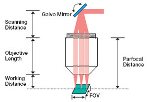
Figure 2.3 Laser Scanning System Schematic
Scanning Distance (SD): The SD is the distance between the aperture plane, where the EP lies, and the back mounting plane of the objective, which is defined as the base of the mounting threads. For these lenses, the mounting plane is the shoulder adjacent to the threads, or thread mounting plane, of the lens. When two galvo mirrors are used, the aperture plane occurs midway between the two mirrors. When one galvo mirror is used, the pivot point of the single mirror coincides with the aperture plane. See the Application Info tab for more details.
Scan Angle (SA): After being routed from the galvo mirror(s) the laser beam is incident on the lens at an angle. This angle, defined with respect to the optical axis of the lens, is the scan angle. When listed in the specification table, it indicates the range of maximum allowed scan angles.
Parfocal Distance (PD): The PD is the distance from the scan lens mounting plane to the front focal plane of the scan lens.
Working Distance (WD or LWD): The distance between the tip of the scan lens housing and the front focal plane of the scan lens is defined as the WD.
Field of View (FOV): The FOV is the maximum size of the area on the sample that can be imaged with a resolution equal to or better than the stated resolution of the scan lenses. This assumes the proper utilization of the scan lenses in the optical system. During operation, the spot positions scan through the FOV.
Depth of View (DOV): The DOV parameter corresponds to the distance between the parallel planes on either side of the front focal plane where the beam spot diameter is √2 greater than it is at the front focal plane. This parameter is of interest when tube lenses are not used in the optical system design and the front focal place is also the sample plane, as is generally the case for OCT. When a tube lens is paired the scan lens, the image plane is located between the scan and the tube lens; the depth of field at the sample is then controlled by the microscope objective.
Spot Size Data
Spot sizes formed in the image plane are typically of more interest to OCT system design than to other laser scanning microscopy system designs. This is because in most OCT systems the image plane is also the sample plane. In other laser scanning applications, scan lenses are routinely paired with tube lenses and the image plane of the scan lens does not coincide with the sample plane.
Spot size plots for these lenses may be viewed by clicking on the icons, ![]() , in the preceding tables. Spot size data are calculated for simulated two-axis and single-axis scans; for the two-axis case a system with two galvo mirrors is simulated, and for the single-axis case a system with a single galvo mirror is simulated. The location of the entrance pupil, which is positioned at the aperture plane, varies depending on whether one or two mirrors are used. When two galvo mirrors are used, the aperture plane is located midway between two galvo mirrors, as is shown in Figure 3.2 in the Application Info tab. When a single galvo mirror is used, the aperture plane falls at the pivot point of the mirror, as is shown in Figure 3.1 in the Application Info tab.
, in the preceding tables. Spot size data are calculated for simulated two-axis and single-axis scans; for the two-axis case a system with two galvo mirrors is simulated, and for the single-axis case a system with a single galvo mirror is simulated. The location of the entrance pupil, which is positioned at the aperture plane, varies depending on whether one or two mirrors are used. When two galvo mirrors are used, the aperture plane is located midway between two galvo mirrors, as is shown in Figure 3.2 in the Application Info tab. When a single galvo mirror is used, the aperture plane falls at the pivot point of the mirror, as is shown in Figure 3.1 in the Application Info tab.
The two-axis scan gives detailed information about the variation in spot size and spot position over an entire two-dimensional range of scan angles; spot sizes over entire image plane are plotted. These data are calculated for a single wavelength (the center wavelength of the lens) and presented as a 3D plot, with the spot size data plotted on the vertical axis.
The 2D single-axis scan graph contains three curves corresponding to: the center wavelength, the minimum specified wavelength, and the maximum specified wavelength. Together they illustrate the dependence of spot size on wavelength. The single-axis scan graphs plot spot size and spot position over a one-dimensional range of scan angles; the spot positions scan a line through the image plane. Because the aperture plane is not located in the same place for the Two-Axis and Single-Axis Scan plots, the data in the Single-Axis plot is not an exact cross section of the Two-Axis Scan plot data. The single-axis scan data were simulated using a system focused at the center wavelength of the lens; the system was not individually focused at each of the three wavelengths.
In optical coherence tomography (OCT) and other laser scanning and imaging systems, a laser beam incident on the back aperture (entrance pupil) of the lens is scanned through a range of angles. This translates the position of the spot formed in the image plane across the lens' field of view. In the case of non-telecentric lenses, this approach to scanning the focal spot through the image plane would introduce severe aberrations that would significantly degrade the quality of the resulting image. Telecentric scan lenses are designed to create a uniform spot size in the image plane at every scan position, which allows a high-quality image of the sample to be formed. Plots showing the spot size and scan position as a function of scan angle are included in the Specs tab.
In general, laser scanning microscopy systems pair a scan lens with a tube lens to create an infinity-corrected optical system. However, most OCT systems are designed to use the scan lens without a tube lens, so that the image plane of the lens coincides with the sample plane. The following discussion assumes the optical system design does not include a tube lens.
When designing an imaging system that uses an LSM scan lens in an OCT configuration, it is important to accommodate the design wavelength, parfocal distance, scanning distance, entrance pupil, and scan angle specifications in order to maximize the image quality (see the Specs tab for scan lens specifications and definitions). As an example, the larger the input beam diameter, the smaller the focused spot size. However, due to the effects of vignetting and/or increased aberrations, the range of scan angles decreases as the diameter of the beam increases. Beams smaller than the entrance pupil specification will result in spot sizes larger than those specified in the Specs tab, and beams with larger diameters will be clipped.
For imaging systems with a single galvo mirror the center of the scan lens' entrance pupil is coincident with the pivot point of the galvo mirror. When a single galvo mirror is used, the scanning distance is measured from the mounting surface of the lens to the pivot point of the mirror. This is shown in Figure 3.1.
If the imaging system uses two galvo mirrors (one to scan in the X direction and one to scan in the Y direction), the entrance pupil is located between the two galvo mirrors, as is shown in Figure 3.2. The scanning distance is then the distance from the mounting surface of the lens to the pivot point of the mirror closest to the lens (d1) plus the distance from the pivot point of that mirror to the entrance pupil (d2). It is important to minimize the distance between the two galvo mirrors, because when the entrance pupil and beam steering pivot point are not coincident, the quality of the image is degraded. This is principally due to the variation in the optical path length as the beam is scanned over the sample. Figures 3.1 and 3.2 are schematics for an imaging system containing one and two galvo mirrors.
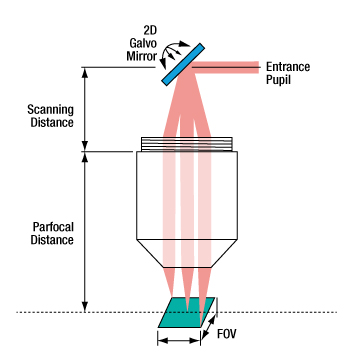
Figure 3.1 When one galvo mirror is used, the entrance pupil is located
at the pivot point of the mirror.
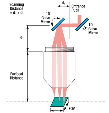
Figure 3.2 When two galvo mirrors are used, the entrance pupil is located between the mirrors.
| Posted Comments: | |
| No Comments Posted |

 Zoom
Zoom| Table G1.1 Key Specificationsa,b | |
|---|---|
| Wavelength Range | 400 to 700 nm |
| Effective Focal Length | 39 mm |
| Lens Working Distance | 25.1 mm |
| Field of View, Maximum | 10.3 x 10.3 mm2 |
| Field of View, Diffraction Limited | 6.9 x 6.9 mm2 |
| Spot Size Plot, 543 nm (Two-Axis Scan) |
 |
| Reflectance | |
| Mounting Threads (External) | M25 x 0.75 |
- For detailed specs, please refer to the Specs tab.
- Click the icons,
 , to view the plots.
- 550 nm Center Wavelength
- Entrance Pupil: 4 mm
- Scan Angle Range: ±10.6° (Maximum, Single Axis)
- External M25 x 0.75 Mounting Threads
The LSM03-VIS scan lens is designed and AR coated for imaging over the visible wavelength range (400 to 700 nm). Key specifications for this lens are listed in Table G1.1; see the Specs tab for complete specifications.
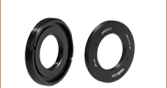
The external M25 × 0.75 threading can be adapted to Thorlabs' standard SM1 (1.035"-40) threading by using an SM1A12 adapter. An RMSA2 adapter allows the scan lens to be used with RMS-threaded (0.800"-36) components.

 Zoom
Zoom| Table G2.1 Key Specificationsa,b | |
|---|---|
| Wavelength Range | 750 to 950 nm |
| Effective Focal Length | 54 mm |
| Lens Working Distance | 64 mm |
| Field of View, Maximum | 18.8 x 18.8 mm2 |
| Field of View, Diffraction Limited | 15.8 x 15.8 mm2 |
| Spot Size Plot, 850 nm (Two-Axis Scan) |
|
| Transmittance | |
| Mounting Threads (External) | M25 x 0.75 |
- For detailed specs, please refer to the Specs Tab.
- Click the icons, , to view the plots.
- 850 nm Center Wavelength
- Large Entrance Pupil: 6 mm
- Wide Scan Angle Range: ±14.0° (Maximum, Single Axis)
- Large Maximum Field of View: 18.8 x 18.8 mm2
- Minimum Spot Size: 14 µm at 850 nm (See Table G2.1)
Compared with many of our other LSM scan lenses, the LSM54 lenses, with their larger entrance pupils and range of scan angles, offer better compatibility with galvo mirrors that are larger and produce more highly deflected beams. Other features made possible through optimized optical design and an increased number of refractive elements include improved chromatic correction and the ability to operate over a wide spectral range. For systems operating in the 950 to 1150 nm or 1200 to 1400 nm wavelength ranges, the LSM54-1050 or LSM54-1310 lenses, respectively, provide similar performance.
Table G2.1 includes key specifications for the LSM54-850 lens, including a representative plot showing the small spot size and the spot position in the image plane as a function of all scanned angles at a wavelength of 850 nm. Click on the icons, ![]() ,
,
The external M25 × 0.75 threading can be adapted to Thorlabs' standard SM1 (1.035"-40) threading by using an SM1A12 adapter. An RMSA2 adapter allows the scan lens to be used with RMS-threaded (0.800"-36) components.

 Zoom
Zoom| Table G3.1 Key Specificationsa,b | ||||
|---|---|---|---|---|
| Item # | LSM02-BB | LSM03-BB | LSM04-BB | LSM05-BB |
| Wavelength Range | 800 to 1100 nmc | |||
| Effective Focal Length | 18 mm | 36 mm | 54 mm | 110 mm |
| Lens Working Distance | 7.5 mm | 25 mm | 42 mm | 94 mm |
| Field of View, Maximum | 4.7 x 4.7 mm2 | 9.4 x 9.4 mm2 | 14.1 x 14.1 mm2 | 28.9 x 28.9 mm2 |
| Field of View, Diffraction Limited |
3.2 x 3.2 mm2 (850 nm) 3.7 x 3.7 mm2 (1050 nm) |
7.9 x 7.9 mm2 (850 nm) 8.6 x 8.6 mm2 (1050 nm) |
14.1 x 14.1 mm2 (850 nm) 14.1 x 14.1 mm2 (1050 nm) |
18.8 x 18.8 mm2 (850 nm) 21.1 x 21.1 mm2 (1050 nm) |
| Spot Size Plot, 850 nm (Two-Axis Scan) |
|
|
|
|
| Spot Size Plot, 1050 nm (Two-Axis Scan) |
|
|
|
|
| Reflectance | c |
|||
| Mounting Thread (External) | M25 x 0.75 | SM2 (2.035"-40) | ||
- For detailed specs, please refer to the Specs Tab.
- Click the icons, , to view the plots.
- While the performance of the AR coatings is optimized around 850 nm and 1050 nm, these lenses are suitable for use in OCT systems with a bandwidth of less than 100 nm within the operating range of 800 nm to 1100 nm.
- Ideal for Wavelengths Around 850 nm and 1050 nm
- Scan Angle Range: ±10.6° (Maximum, Single Axis)
- Range of Effective Focal Length Options from 18 to 110 mm
These lenses can be used in OCT systems with a bandwidth of less than 100 nm, within the operating range of 800 to 1100 nm. The performance of the AR coatings on these lenses is optimized around 850 nm and 1050 nm, two popular wavelengths for OCT. Selected specifications are quoted in Table G3.1, including a representative plot of the reflectance near the target wavelengths. For additional specifications, please see the Specs tab.
The external M25 × 0.75 threading can be adapted to Thorlabs' standard SM1 (1.035"-40) threading by using an SM1A12 adapter. An RMSA2 adapter allows the scan lens to be used with RMS-threaded (0.800"-36) components.

 Zoom
Zoom| Table G4.1 Key Specificationsa,b | |
|---|---|
| Wavelength Range | 950 to 1150 nm |
| Effective Focal Length | 54 mm |
| Lens Working Distance | 64 mm |
| Field of View, Maximum | 18.8 x 18.8 mm2 |
| Field of View, Diffraction Limited | 18.0 x 18.0 mm2 |
| Spot Size Plot, 1050 nm (Two-Axis Scan) |
|
| Transmittance | |
| Mounting Threads (External) | M25 x 0.75 |
- For detailed specs, please refer to the Specs Tab.
- Click the icons, , to view the plots.
- 1050 nm Center Wavelength
- Large Entrance Pupil: 6 mm
- Wide Scan Angle Range: ±14.0° (Maximum, Single Axis)
- Large Maximum Field of View: 18.8 x 18.8 mm2
- Minimum Spot Size: 18 µm at 1050 nm (See Table G4.1)
Compared with many of our other LSM scan lenses, the LSM54 lenses, with their larger entrance pupils and range of scan angles, offer better compatibility with galvo mirrors that are larger and produce more highly deflected beams. Other features made possible through optimized optical design and an increased number of refractive elements include improved chromatic correction and the ability to operate over a wide spectral range. For systems operating in the 750 to 950 nm or 1200 to 1400 nm wavelength ranges, the LSM54-850 or LSM54-1310 lenses, respectively, provide similar performance.
Table G4.1 includes key specifications for the LSM54-1050 lens, including a representative plot showing the small spot size and the spot position in the image plane as a function of all scanned angles at a wavelength of 1050 nm. Click on the icons, ![]() ,
,
The external M25 × 0.75 threading can be adapted to Thorlabs' standard SM1 (1.035"-40) threading by using an SM1A12 adapter. An RMSA2 adapter allows the scan lens to be used with RMS-threaded (0.800"-36) components.

 Zoom
Zoom| Table G5.1 Key Specificationsa,b | |
|---|---|
| Wavelength Range | 1200 to 1400 nm |
| Effective Focal Length | 54 mm |
| Lens Working Distance | 64 mm |
| Field of View, Maximum | 18.8 x 18.8 mm2 |
| Field of View, Diffraction Limited | 18.8 x 18.8 mm2 |
| Spot Size Plot, 1300 nm (Two-Axis Scan) |
|
| Transmittance | |
| Mounting Threads (External) | M25 x 0.75 |
- For detailed specs, please refer to the Specs Tab.
- Click the icons, , to view the plots.
- 1300 nm Center Wavelength
- Large Entrance Pupil: 6 mm
- Wide Scan Angle Range: ±14.0° (Maximum, Single Axis)
- Large Maximum Field of View: 18.8 x 18.8 mm2
- Minimum Spot Size: 22 µm at 1300 nm (See Table G5.1)
Compared with many of our other LSM scan lenses, the LSM54 lenses, with their larger entrance pupils and range of scan angles, offer better compatibility with galvo mirrors that are larger and produce more highly deflected beams. Other features made possible through optimized optical design and an increased number of refractive elements include improved chromatic correction and the ability to operate over a wide spectral range. For systems operating in the 750 to 950 nm or 950 to 1150 nm wavelength ranges, the LSM54-850 or LSM54-1050 lenses, respectively, provide similar performance.
Table G5.1 includes key specifications for the LSM54-1310 lens, including a representative plot showing the small spot size and the spot position in the image plane as a function of all scanned angles at a wavelength of 1300 nm. Click on the![]() ,
,
The external M25 × 0.75 threading can be adapted to Thorlabs' standard SM1 (1.035"-40) threading by using an SM1A12 adapter. An RMSA2 adapter allows the scan lens to be used with RMS-threaded (0.800"-36) components.

 Zoom
Zoom| Table G6.1 Key Specificationsa,b | ||||
|---|---|---|---|---|
| Item # | LSM02 | LSM03 | LSM04 | LSM05 |
| Wavelength Range | 1250 to 1380 nm | |||
| Effective Focal Length | 18 mm | 36 mm | 54 mm | 110 mm |
| Lens Working Distance | 7.5 mm | 25.1 mm | 42.3 mm | 93.8 mm |
| Field of View, Maximum | 4.7 x 4.7 mm2 | 9.4 x 9.4 mm2 | 14.1 x 14.1 mm2 | 28.9 x 28.9 mm2 |
| Field of View, Diffraction Limited |
4.2 x 4.2 mm2 | 9.3 x 9.3 mm2 | 14.1 x 14.1 mm2 | 23.8 x 23.8 mm2 |
| Spot Size plot, 1315 nm (Two-Axis Scan) |
|
|
|
|
| Mounting Threads (External) | M25 x 0.75 | SM2 (2.035"-40) | ||
- For detailed specs, please refer to the Specs tab.
- Click the icons, , to view the plots.
- 1315 nm Center Wavelength
- Entrance Pupil: 4 mm
- Scan Angle Range: ±10.6° (Maximum, Single Axis)
- Range of Effective Focal Length Options
- External M25 x 0.75 Mounting Threads
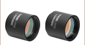
The LSM02, LSM03, LSM04, and LSM05 scan lenses are designed and have AR coatings for imaging centered around 1315 nm in the near-infrared.
Representative plots of the spot size along the sagittal and tangential scan directions can be seen by clicking on the icons, ![]() , in Table G6.1. For a detailed list of specifications, please see the Specs tab.
, in Table G6.1. For a detailed list of specifications, please see the Specs tab.
The external M25 × 0.75 threading can be adapted to Thorlabs' standard SM1 (1.035"-40) threading by using an SM1A12 adapter. An RMSA2 adapter allows the scan lens to be used with RMS-threaded (0.800"-36) components.