 Products Home / Imaging Systems / OCT Imaging Systems & Components / Ganymede™ Series SD-OCT Systems
Ganymede™ Series SD-OCT Systems

Please Wait
Exploring the Options?

We can provide tailored recommendations and partner with you to obtain images of your samples, demonstrating the impact of the OCT base unit and probe optics on image quality. Demos of our OCT systems can be arranged at our Sterling, VA (USA); Shanghai, China; Tokyo, Japan; and Lübeck, Germany facilities. See the OCT Demo Rooms tab.
In the Budgetary Phase?
System prices vary based on the exact components. Through our conversations, we can ensure your system quote is tailored to your requirements.
OEM or Custom Projects?
Click here to learn about our OEM capabilities.

OCT Applications Team Based in Lübeck, Germany
We're Happy to Assist!

OCT Family Updates
We recently improved the OCT Base Units, and the new additions include:
- Fully Configurable Trigger for Integration into Larger Experiments
- Analog Input for Combining Other Data Sources with the OCT Signal
- Internal Hardware Diagnostics for Improved Troubleshooting
The SD-OCT standard scanners have also been redesigned with a new micrometer screw for more precise reference arm positioning.
New features added to ThorImage®OCT include a despeckle filter, 3D speckle variance mode, and automatic peak detection.
Features
- Configurable High-Resolution OCT Systems
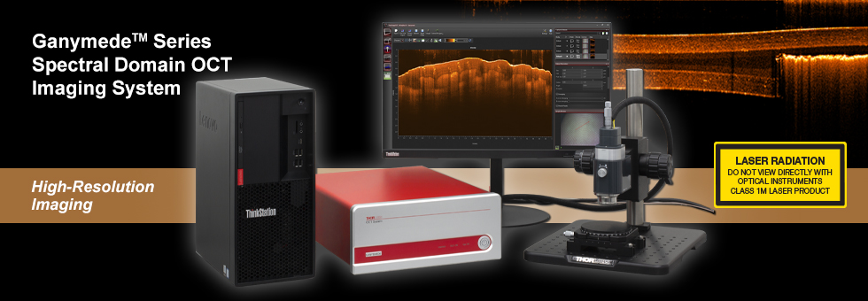
- SD-OCT Systems with 880 nm Center Wavelength (See Tables Below for Specifications)
- A-Scan Rates up to 248 kHz
- Imaging Depths in Air up to 3.4 mm
- Axial Resolutions in Air from <3.0 to 6.0 µm
- Sensitivities up to 106 dB
- Includes Computer and ThorImage®OCT Software Package
(See the Software Tab) - Build-Your-Own and Preconfigured Systems Available
Choose Components to Build or Customize Your OCT System
- Choose from Base Units Optimized for a Range of Applications
- Standard and User-Customizable Scanners Available
- Data Acquisition via USB 3.0 or CameraLink Connection
- Scan Lens Kits to Optimize Lateral Resolution and Focal Length for Your Application
- Ring- and Immersion-Style Sample Z-Spacers for Air or Liquid Imaging Applications
- Scanner Stand and Translation Stage Accessories
- Contact Our OCT Team to Request a Quote and Discuss Building a System
Optical Coherence Tomography (OCT) is a noninvasive optical imaging technique that produces real-time, 2D cross-sectional and 3D volumetric images of a sample. This technique provides structural information about the sample based on light backscattered from different layers of material within that sample, producing images with micron-level resolution and millimeters of imaging depth. OCT imaging can be considered as an optical analog to ultrasound imaging that achieves higher resolution at the cost of decreased penetration depth. In addition to high resolution, the non-contact, noninvasive nature of OCT makes it well suited for imaging samples such as biological tissue, small animals, and industrial materials.
Thorlabs' Ganymede™ Series of OCT Imaging Systems provide the flexibility required for high-resolution imaging applications with A-scan line rates up to 248 kHz. The 64-bit software pre-installed on the included computer displays and processes 2D and 3D OCT data in real time. Scanner options include a robust standard scanner and a user-customizable scanner. Optional accessories are available below to customize your OCT system to meet the requirements of your application. Additionally, Thorlabs offers five complete, preconfigured OCT systems operating with 880 nm center wavelengths based on the components sold on this page.
The components below can also be used to upgrade your existing Thorlabs OCT system with additional features and are fully compatible out of the box with Thorlabs' OCT systems and accessories. While most systems are upgradable, we recommend contacting the OCT Team to determine the optimal solution for your system and intended application.
Click on the Image Below or in the Table to the Right for Details on Customization Options

| Ganymede Customization Options |
|---|
| OCT Base Unit (Computer Included) |
| Scanning System |
| Scan Lens Kit |
| Reference Length Adapter (For Standard Scanners Only) |
| Adjustable Scanner Stand |
| Translation Stage |
| Preconfigured Systems |
| ThorImageOCT Documentation | |
|---|---|
| ThorImageOCT Software Manual | |
| Third-Party Software License Agreements | |
ThorImage®OCT Software Index
- Introduction
- Scan Control
- Processing Options for Improving the Image Quality of OCT Images
- Data Analysis for Measuring the Thickness of Layers
- Third-Party Applications to Export/Reimport OCT Data
- Imaging Modes
- 1D Mode for Single Point Measurements
- 2D Mode for Cross-Sectional Imaging
- 3D Mode for Volume Imaging
- Doppler Mode for Doppler Flow Imaging
- Speckle Variance Mode for Angiographic Imaging
- Externally-Triggered Acquisition for Synchronized Measurements
- Analog Input for Synchronization with other Modalities
- Software Development Kits for Writing Custom Programs
- Probe Calibration for Different Configurations
- Video Showing Screencast of Rendering Capabilities
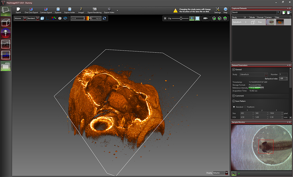
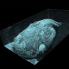
Click to Enlarge
Rendered Volume of a Zebrafish with Modifiable Clipping Plane
ThorImageOCT Software
- Interactive Scan Position Control through Video Display for Common Line Scans or Freeform Pattern Scans
- Advanced Dataset Management
- Access to Raw Spectra, Processsed Data, and All Calibration Files Necessary for User-Designed Processing Routines
- High-Speed Volume Rendering of 3D Data
- Doppler and Speckle Variance Imaging
- Versatile Scan and Acquisition Control, such as Averaging or Adjustable Scan Speeds
ThorImageOCT is a high-performance data acquisition software that is included with all Thorlabs OCT systems. This 64-bit Windows-based software acquires and displays OCT data, as well as includes scan control and processing options. Additionally, NI LabVIEW and C-based Software Development Kits (SDKs) are available, which contain a complete set of libraries for measurement control, data acquisition, and processing, as well as for storage and display of OCT images. The SDKs provide the means for developing highly specialized OCT imaging software for every individual application.
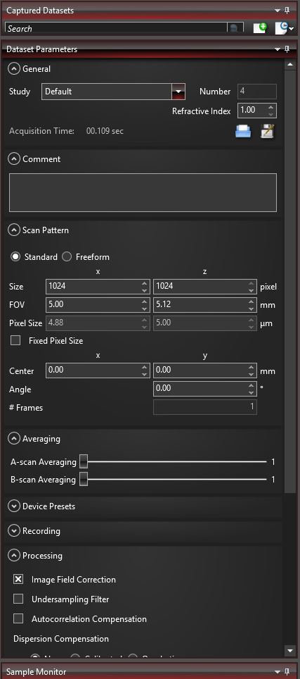
Click to Enlarge
Various acquisition parameters can be adjusted in ThorImageOCT.
Scan Control
ThorImageOCT provides numerous scan and acquisition controls. The camera integrated in the scanner of our OCT systems provides live video images in the application software. Defining the scan line for 2D imaging or the scan area for 3D imaging is accomplished through the easy-to-use "Draw and Scan" feature by clicking on the video image.
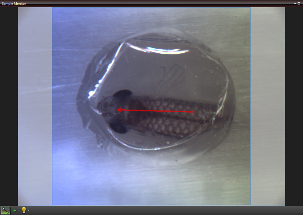
Click to Enlarge
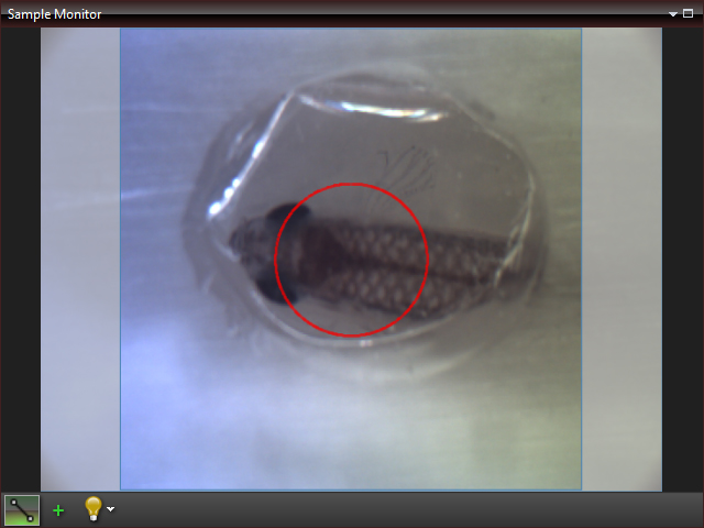
The Sample Monitor can be used to define the scan pattern using the "Draw and Scan" feature.
Arbitrary forms defined by the Draw & Scan feature or loaded .txt files can be scanned. The scan pattern can also be adjusted by specifying suitable parameters in the controls of the software, as shown to the right.
Click to Enlarge
A predefined circle scan pattern can be loaded and scanned in the software. The size can be changed with the Zoom feature.
Click to Enlarge
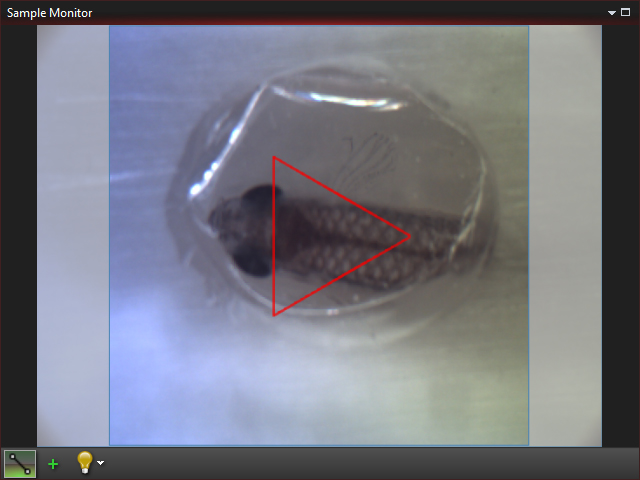
A predefined triangle scan pattern can be loaded and scanned in the software. The size can be changed with the Zoom feature.
Additionally, one can further set processing parameters, averaging parameters, and the speed and sensitivity of the device using device presets. By using a high-speed preset, video-like frame rates in 2D and fast volume rendering in 3D are possible, whereas high-sensitivity acquisition is enabled by choosing a preset with a lower acquisition speed.
Click to Enlarge
Despeckle Filter Applied to an OCT Image of a Human Tooth

Click to Enlarge
OCT Image of a Human Tooth
Processing Options
ThorImageOCT provides features specifically designed to improve the quality of OCT images. The data can be modified during acquisition using processing parameters, such as image field correction and undersampling filters, or afterwards with filters. As shown to the right, the despeckle filter can be applied to an image to reduce speckle noise without blurring details of the imaged structure.
If additional processing functions are desired, ThorImageOCT can also integrate user-defined post-processing algorithms; see the Third Party Applications section for more details.
Click to Enlarge
The marker tool can be used to measure layer thickness.
Data Analysis
ThorImageOCT includes several tools for convenient data analysis. The integrated marker tool serves to measures distances, as well as the structure size. Additionally, this tool can be used to display intensity profile of the OCT data across a line. For precise distance and thickness measurements, the refractive index of the material under investigation can be set.
Click to Enlarge
The Dataset Management Window of ThorImageOCT
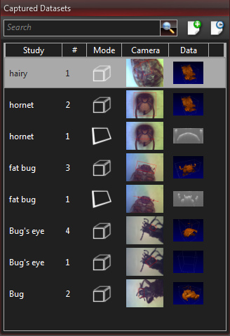
Dataset Management
ThorImageOCT provides advanced dataset management capabilities, which allow several datasets to be opened simultaneously. Datasets are uniquely defined using an identifier consisting of a study (or test series) name and an experiment number. Grouping of datasets can be achieved by using the same study name. The "Captured Datasets" list shows an overview of all open datasets, including the dataset identifier, the acquisition mode, and preview pictures of the still video image and the OCT data.
Datasets can be exported in various image formats, such as PNG, BMP, JPEG, PDF, or TIFF. The set can also be exported in complete data formats suited for post-processing purposes, such as RAW/SRM, FITS, VTK, VFF, and 32-bit floating-point TIFF.
The OCT file format native to ThorImageOCT allows OCT data, sample monitor data, and all relevant metadata to be stored in a single file. ThorImageOCT can also be installed and run on computers without OCT devices in order to view and export OCT data. The user has full access to the raw and processed data from the device, including additional data used for processing, e.g. offset errors.
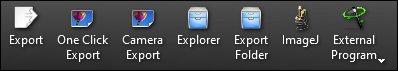
Export buttons are accessible in the Action Toolbar of ThorImageOCT.
Third-Party Applications
If both ImageJ and ThorImageOCT are installed on the computer, opening acquired OCT data in ImageJ is one mouse click away. This enables a smooth workflow when requiring the advanced image processing functionality provided by ImageJ. Clicking the Explorer button will open the folder and select the file in Windows Explorer where the currently active dataset is stored.
Click to Enlarge
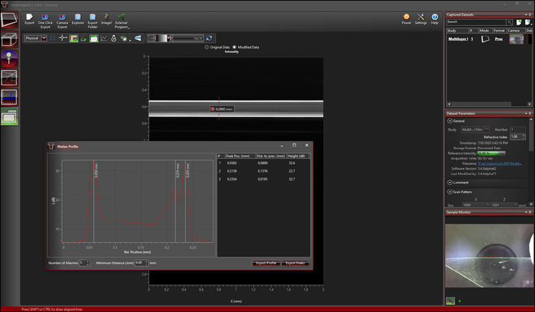
After smoothing the data in ImageJ, the marker tool in ThorImageOCT can be used to measure layer thickness.
Click to Enlarge
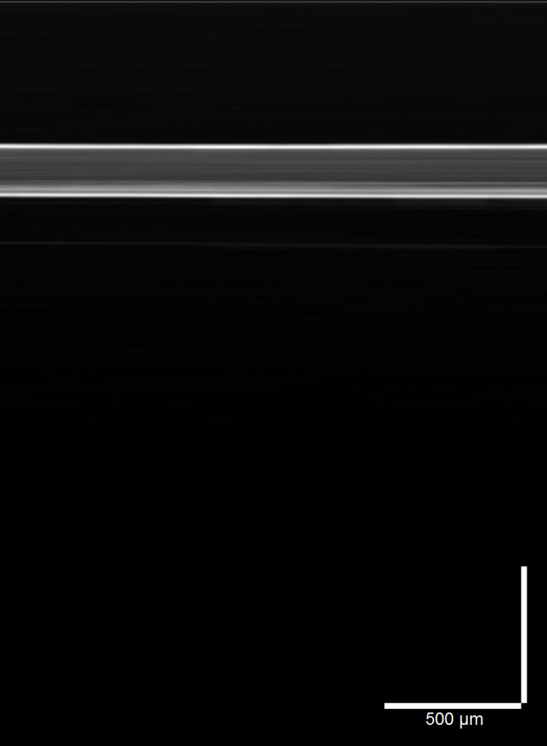
A filter for smoothing lateral directions is applied to the image in ImageJ.
Click to Enlarge
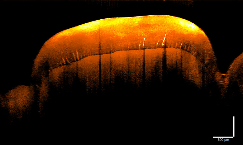
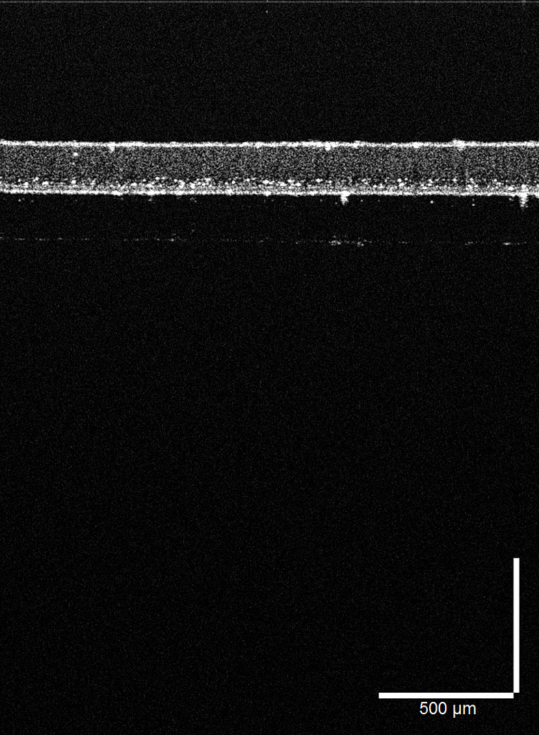
OCT data of a plastic multilayered film with speckle.
Acquired OCT datasets can also be exported and modified in a third-party program, and then reimported back into the ThorImageOCT software. This functionality allows for fast and customized modifications of OCT images, while still using the dataset management of the ThorImageOCT software. As shown in the example to the right, OCT data (left) can be exported to ImageJ and a smoothing filter applied in the lateral direction (center). Using the "External Program" button allows the modified data to be reimported into ThorImageOCT for further analysis. For example, the peak detection tool can be used to measure the layer thicknesses (right).
Imaging Modes
Different OCT imaging modes can be selected using the mode selector. If the ThorImageOCT software finds a compatible system connected and switched on, all operational modes will be selectable. If no OCT device is present, only the data viewing mode for viewing and OCT data export will be available.
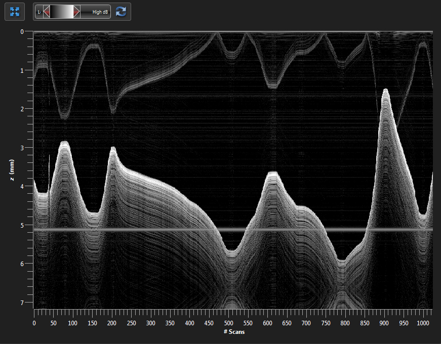
Click to Enlarge
Several A-Scans at a Single Point Over Time (M-Scan)
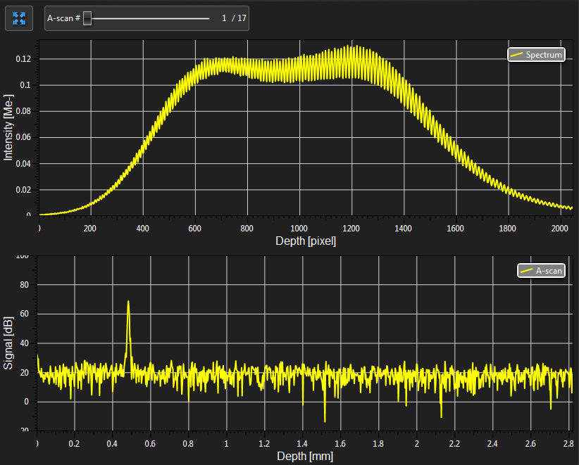
Click to Enlarge
Spectral and Depth Information for a Single Point (A-Scan)
1D Mode
In this mode, single-point measurements can be made that provide spectral and depth information, as well as the ability to observe time-related sample behavior with an M-scan.
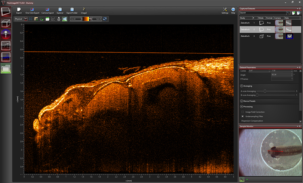
Click to Enlarge
ThorImageOCT Window in the 2D Mode
2D Mode
In the 2D imaging mode, the probe beam scans in one direction, acquiring cross-sectional OCT images which are then displayed in real time. Line averaging before or after the Fast Fourier Transform (FFT) is available, as well as B-Scan averaging. For long term measurements, a time series function, which has an adjustable time interval between two acquisitions, is included. Image display parameters, such as color mapping, can be controlled in this mode. We have also implemented an option for automatic calculation of the optimum contrast and brightness of the displayed OCT images.
3D Mode
In the 3D imaging mode, the OCT probe beam scans sequentially across the sample to collect a series of 2D cross-sectional images which are then processed to build a 3D image.
To accommodate long term measurements, a time series function that takes a series of 3D measurements is available. The number of volumes to be acquired and the time interval between scans are adjustable.
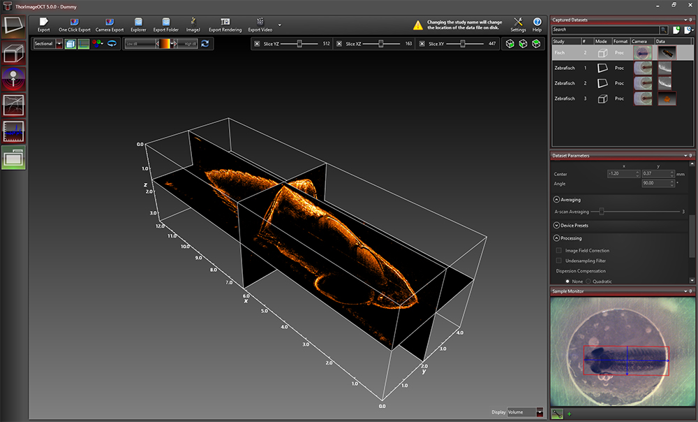
In the ThorImageOCT software, 3D volume datasets can be viewed as orthogonal cross-sectional planes (see below) and volume renderings.
The Sectional View features cross-sectional images in all three orthogonal planes, independent of the orientation in which the data was acquired. The view can be rotated as well as zoomed in and out.
The Rendering View provides a volumetric rendering of the acquired volume dataset. This view enables quick 3D visualization of the sample being imaged. Planes of any orientation can be clipped to expose structures within the volume. The 3D image can be zoomed in and out as well as rotated. Furthermore, the coloring and dynamic range settings can be adjusted.
Utilizing the full potential of our high-performance software in combination with our high-speed OCT systems, we have included a Fast Volume Rendering Mode in the ThorImageOCT software, which serves as a preview for high-resolution 3D acquisitions. In this mode, high-speed volume renderings can be displayed in real-time, providing rapid visualization of samples in three dimensions.
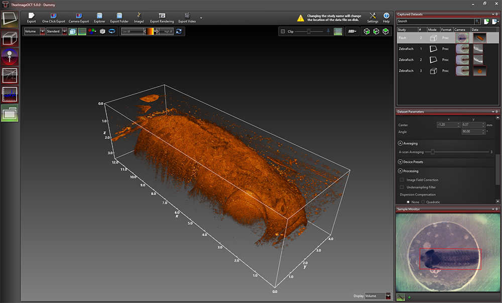
Click to Enlarge
Rendering View in ThorImageOCT
Click to Enlarge
Sectional View in ThorImageOCT
Click to Enlarge
Doppler dataset showing the velocity of a rotated plastic stick with opposite flow directions.
Doppler Mode
Doppler OCT imaging comes standard with all OCT systems. In the Doppler mode, phase shifts between adjacent A-scans are averaged to calculate the Doppler frequency shift induced by particle motion or flow. The number of lateral and axial pixels can be modified to change velocity sensitivity and resolution during phase shift calculation. The Doppler images are displayed in the main window with a color map indicating forward- or backward-directed flow, relative to the OCT beam.
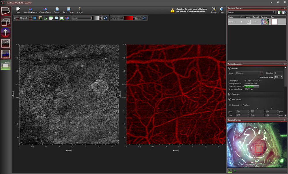
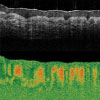
Click to Enlarge
Speckle variance measurement showing blood vessels of a mouse brain.
Speckle Variance Mode
The speckle variance imaging mode is an acquisition mode which uses the variance of speckle noise to calculate angiographic images. It can be used to visualize three dimensional vessel trees without requiring significant blood flow and without requiring a specific acquisition speed window. The speckle variance data can be overlaid on top of intensity pictures providing morphological information. Different color maps can be used to display the multimodal pictures.
Externally-Triggered Acquisition
ThorImageOCT and the SDK APIs provide the ability to externally trigger the acquisition of A-Scans. This enables the user to synchronize measurements from different modalities (e.g. vibrometry and synchronized positioning) with an OCT measurement. Synchronization is greatly simplified with all current CameraLink-based Thorlabs OCT systems (a TTL level trigger signal source required). External triggering is available for all imaging modes and can be toggled in the settings dialog in ThorImageOCT.
Thorlabs' current generation of Ganymede (Item # GANxxx) and Telesto (Item #s TELxx1 & TELxx1PS) SD-OCT Systems include an external B-Scan trigger for synchronization with other experiments.
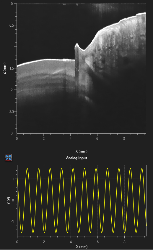
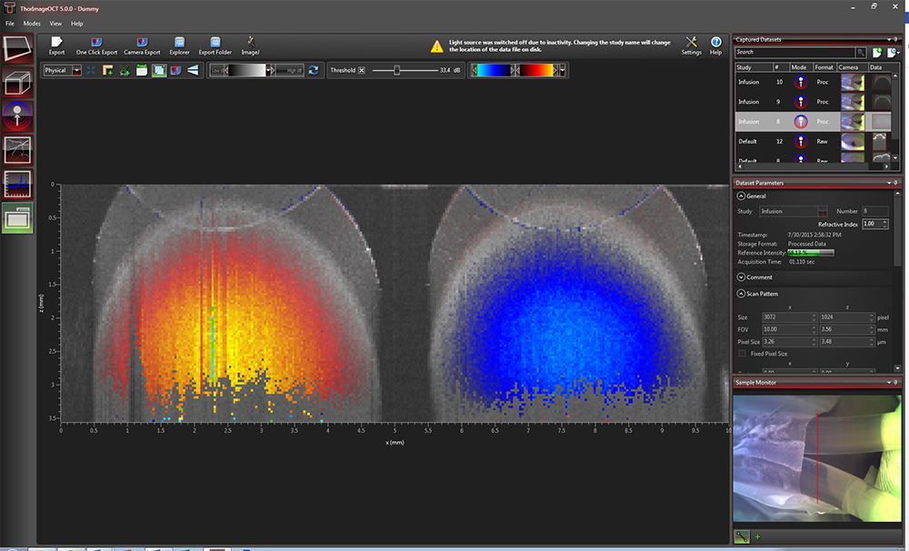
Click to Enlarge
Analog Data Visualization in the 2D Display
Analog Input for Synchronization with Other Modalities
Thorlabs' current generation of Ganymede (Item # GANxxx) and Telesto (Item #s TELxx1 & TELxx1PS) SD-OCT Systems include two analog input channels, which can be used to combine imaging modalities. The analog signal from another data source (i.e., fluorescence signal) is sampled and displayed simultaneously with the OCT signal.
Software Development Kits
For maximum flexibility, customized solutions can be implemented in ThorImageOCT using software development kits (SDKs). Experienced software developers can use these in a multitude of programming environments to tailor the use of Thorlabs OCT systems to their specific application. SDKs are available in:
- ANSI C with C++ Demo Programs
- LabVIEW® Including Demo Programs and Advanced Sample Code
Click to Enlarge
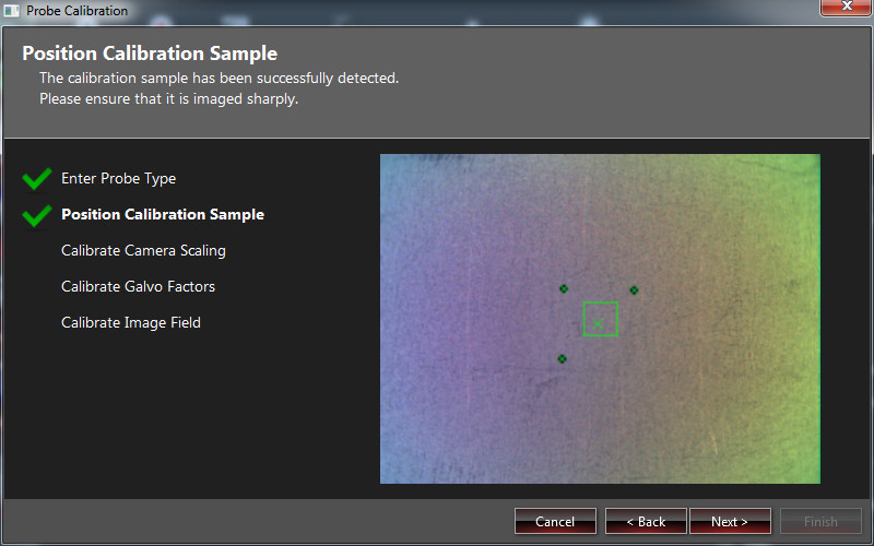
Probe Calibration Window in ThorImageOCT
Probe Calibration
Changing to a different scan lens kit will generally require a different probe configuration in order to adapt to changes in the optical parameters of the system. When an additional scan lens is purchased for your Thorlabs OCT scanner system, ThorImageOCT enables you to easily create a fitting configuration for your new scan lens by using the calibration sample shipped with the lens and an intuitive step-by-step calibration process (shown to the right).
Video Showing Screencast of ThorImageOCT Rendering Capabilities
In this video, OCT images of a finger are acquired and manipulated in the 3D volume and cross section modes.
For information on the availability of ThorImageOCT version 5.5, please contact our OCT Support Team.
Optical Coherence Tomography Tutorial
Optical Coherence Tomography (OCT) is a noninvasive optical imaging modality that provides real-time, 1D depth, 2D cross-sectional, and 3D volumetric images with micron-level resolution and millimeters of imaging depth. OCT images consist of structural information from a sample based on light backscattered from different layers of material within the sample. It can provide real-time imaging and is capable of being enhanced using birefringence contrast or functional blood flow imaging with optional extensions to the technology.
Thorlabs has designed a broad range of OCT imaging systems that cover several wavelengths, imaging resolutions, and speeds, while having a compact footprint for easy portability. Also, to increase our ability to provide OCT imaging systems that meet each customer’s unique requirements, we have designed a highly modular technology that can be optimized for varying applications.
Application Examples
Art Conservation
Drug Coatings

3D Profiling
In Vivo
Small Animal
Biology
Tissue Birefringence
Mouse Lung
Retina Cone Cells

Click to Enlarge
Figure 1
Click to Enlarge
Figure 2
OCT is the optical analog of ultrasound, with the tradeoff being lower imaging depth for significantly higher resolution (see Figure 1). With up to 15 mm imaging range and better than 5 micrometers in axial resolution, OCT fills a niche between ultrasound and confocal microscopy.
In addition to high resolution and greater imaging depth, the non-contact, noninvasive advantage of OCT makes it well suited for imaging samples such as biological tissue, small animals, and materials. Recent advances in OCT have led to a new class of technologies called Fourier Domain OCT, which has enabled high-speed imaging at rates greater than 700,000 lines per second.1
Fourier Domain Optical Coherence Tomography (FD-OCT; Figure 2) is based on low-coherence interferometry, which utilizes the coherent properties of a light source to measure optical path length delays in a sample. In OCT, to obtain cross-sectional images with micron-level resolution, and interferometer is set up to measure optical path length differences between light reflected from the sample and reference arms.
There are two types of FD-OCT systems, each characterized by its light source and detection schemes: Spectral Domain OCT (SD-OCT) and Swept Source OCT (SS-OCT). In both types of systems, light is divided into sample and reference arms of an interferometer setup, as illustrated in Figure 3. SS-OCT uses coherent and narrowband light, whereas SD-OCT systems utilize broadband, low-coherence light sources. Back scattered light, attributed to variations in the index of refraction within a sample, is recoupled into the sample arm fiber and then combined with the light that has traveled a fixed optical path length along the reference arm. A resulting interferogram is measured through the detection arm of the interferometer.
The frequency of the interferogram measured by the sensor is related to depth locations of the reflectors in the sample. As a result, a depth reflectivity profile (A-scan) is produced by taking a Fourier transform of the detected interferogram. 2D cross-sectional images (B-scans) are produced by scanning the OCT sample beam across the sample. As the sample arm beam is scanned across the sample, a series of A-scans are collected to create the 2D image.
Similarly, when the OCT beam is scanned in a second direction, a series of 2D images are collected to produce a 3D volume data set. With FD-OCT, 2D images are collected on a time scale of milliseconds, and 3D images can be collected at rates now below 1 second.
Spectral Domain OCT vs. Swept Source OCT
Spectral Domain and Swept Source OCT systems are based on the same fundamental principle but incorporate different technical approaches for producing the OCT interferogram. SD-OCT systems have no moving parts and therefore have high mechanical stability and low phase noise. Availability of a broad range of line cameras has also enabled development of SD-OCT systems with varying imaging speeds and sensitivities.
SS-OCT systems utilize a frequency swept light source and photodetector to rapidly generate the same type of interferogram. Due to the rapid sweeping of the swept laser source, high peak powers at each discrete wavelength can be used to illuminate the sample to provide greater sensitivity with little risk of optical damage.
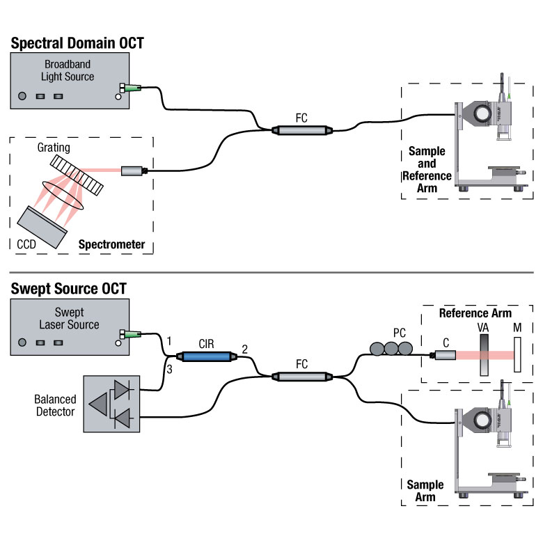
Click to Enlarge
Figure 3
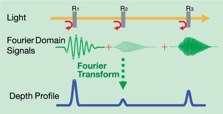
FD-OCT Signal Processing
In Fourier Domain OCT, the interferogram is detected as a function of optical frequency. With a fixed optical delay in the reference arm, light reflected from different sample depths produces interference patterns with the different frequency components. A Fourier transform is used to resolve different depth reflections, thereby generating a depth profile of the sample (A-scan).
1V.Jayaraman, J. Jiang, H.Li, P. Heim, G. Cole, B. Potsaid, J. Fujimoto, and A. Cable, "OCT Imaging up to 760 kHz Axial Scan Rate Using Single-Mode 1310 nm MEMs-Tunable VCSELs with 100 nm Tuning Range," CLEO 2011 - Laser Applications to Photonic Applications, paper PDPB2 (2011).
Brochure and Configuration Chart
The buttons below link to PDFs of printable materials and a graphical customization guide for our Ganymede™ Series OCT Systems.


Click to Enlarge
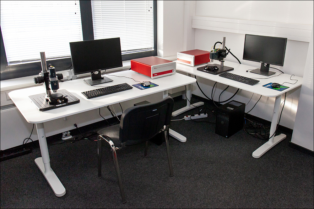
Lübeck Demo Room
Try Our OCT Imaging Systems In Person or Virtually
From our OCT facility in Lüebeck, Germany and offices in Virginia, USA; Tokyo, Japan; and Shanghai, China; Thorlabs' application specialists and sales engineers look forward to helping you determine the best OCT system to meet your specific experimental needs. We can provide tailored recommendations and partner with you to obtain images of your samples, demonstrating the impact of the OCT base unit and probe optics on image quality.
Thorlabs' worldwide network allows us to operate demo rooms in a number of locations where you can see our OCT systems in action. We welcome the opportunity to work with you in person or virtually. A demo can be scheduled at any of our showrooms or virtually by contacting OCT@thorlabs.com.
Demo Rooms and Customer Support Sites
(Click Each Location for More Details)
Lübeck, Germany
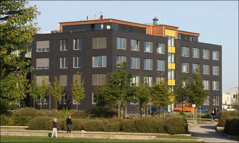
Thorlabs GmbH
Maria-Goeppert-Straße 9
23562 Lübeck
Customer Support
- Phone: +49 (0) 8131-5956-40840
- Email: oct@thorlabs.com
Demo Rooms
- Ganymede™ Series SD-OCT Systems
- Telesto® Series SD-OCT Systems
- Telesto® Series PS-OCT Systems
- Atria® Series SS-OCT Systems
- Vega™ Series SS-OCT Systems
Sterling, Virginia, USA
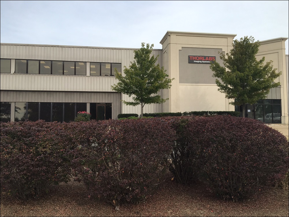
Thorlabs Imaging Systems HQ
108 Powers Court
Sterling, VA 20166
Customer Support
- Phone: (703) 651-1700
- E-mail: ImagingTechSupport@thorlabs.com
Demo Rooms
Nerima-ku, Tokyo, Japan
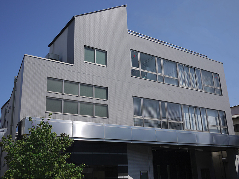
Thorlabs Japan, Inc.
3-6-3 Kitamachi
Nerima-ku, Tokyo 179-0081
Customer Support
- Phone: +81-3-6915-7701
- Email: sales@thorlabs.jp
Demo Rooms
Shanghai, China
Thorlabs China
Room A101, No. 100, Lane 2891, South Qilianshan Road
Shanghai 200331
Customer Support
- Phone: +86 (0)21-60561122
- Email: techsupport-cn@thorlabs.com
Demo Rooms
Customer Support Sites
(Click Each Location for More Details)
Newton, New Jersey, USA
Thorlabs HQ
43 Sparta Avenue
Newton, NJ 07860
Customer Support
- Phone: (973) 300-3000
- E-mail: techsupport@thorlabs.com
Ely, United Kingdom

Thorlabs Ltd.
1 Saint Thomas Place, Ely
Ely CB7 4EX
Customer Support
- Phone: +44 (0)1353-654440
- E-mail: techsupport.uk@thorlabs.com
Bergkirchen, Germany
Thorlabs GmbH
Münchner Weg 1
85232 Bergkirchen
Customer Support
- Phone: +49 (0) 8131-5956-0
- E-mail: europe@thorlabs.com
Maisons-Laffitte, France
Thorlabs SAS
109, rue des Cotes
Maisons-Laffitte 78600
Customer Support
- Phone: +33 (0)970 440 844
- E-mail: techsupport.fr@thorlabs.com
São Carlos, SP, Brazil
Thorlabs Vendas de Fotônicos Ltda.
Rua Rosalino Bellini, 175
Jardim Santa Paula
São Carlos, SP, 13564-050
Customer Support
- Phone: +55-16-3413 7062
- E-mail: brasil@thorlabs.com
| Posted Comments: | |
Jan van Nieuwkasteele
(posted 2023-04-04 13:52:22.167) We have a Ganymede M00290244, In the software manual a reference is made to the hardware manual of the particular instrument.
Do you have a pdf of the hardware manual of this instrument |
Thorlabs offers a variety of OCT Imaging Systems to meet a range of application requirements. The OCT base unit and scan lens kit are key to OCT system performance. Significant performance characteristics, including axial resolution, A-Scan rate, and imaging depth, are entirely or strongly dependent on the design of the OCT base unit. The choice of scan lens kit determines other parameters, such as lateral resolution and field of view. Thorlabs offers a variety of OCT base units and scan lens kits that provide foundations for systems with a wide range of capabilities. The tables below present key performance parameters of our base units and include links to our other OCT imaging system pages. We encourage you to contact us directly at oct@thorlabs.com or via our online request form to discuss specific imaging requirements.
Swept Source OCT Base Units
| Base Unit Item #a | ATR206 | ATR220 | VEG210 | VEG220 |
|---|---|---|---|---|
| Series Name (Click for Link) | Atria® | Vega™ | ||
| Key Performance Feature(s) | Long Imaging Range | High Speed | Long Imaging Range | |
| High Resolution | General Purpose | High Speed | ||
| Center Wavelength | 1060 nm | 1300 nm | ||
| Imaging Depthb (Air/Water) | 20 mm / 15 mm | 6.0 mm / 4.5 mm | 11 mm / 8.3 mm | 8.0 mm / 6.0 mm |
| Axial Resolutionb (Air/Water) | 11 µm / 8.3 µm | 14 µm / 10.6 µm | ||
| A-Scan Line Rate | 60 kHz | 200 kHz | 100 kHz | 200 kHz |
| Sensitivity (Max)c | 102 dB | 97 dB | 102 dB | 98 dB |
Spectral Domain OCT Base Units
| Base Unit Item #a | GAN111 | GAN312 | GAN612 | GAN332 | GAN632 |
|---|---|---|---|---|---|
| Series Name | Ganymede™ | ||||
| Key Performance Feature(s) | High Resolution | High Resolution | Very High Resolution | ||
| High Speed | Very High Speed | High Speed | Very High Speed | ||
| Center Wavelength | 880 nm | ||||
| Imaging Depthb (Air/Water) | 3.4 mm / 2.5 mm | 3.4 mm / 2.5 mm | 1.6 mm / 1.2 mm | ||
| Axial Resolutionb (Air/Water) | 6.0 µm / 4.5 µm | 6.0 µm / 4.5 µm | <3.0 µm / <2.2 µm | ||
| A-Scan Line Rate | 1.5 kHz to 20 kHz | 1.5 kHz to 80 kHz | 5 kHz to 248 kHz | 1.5 kHz to 80 kHz | 5 kHz to 248 kHz |
| Sensitivity (Max)c | 106 dB | 106 dB | 102 dB | 106 dB | 102 dB |
| Base Unit Item #a | TEL221 | TEL321 | TEL411 | TEL511 | TEL211PS | TEL221PS |
|---|---|---|---|---|---|---|
| Series Name (Click for Link) | Telesto® | Telesto® PS-OCT | ||||
| Key Performance Feature(s) | High Resolution | High Imaging Depth | High Imaging Depth | High Resolution | ||
| General Purpose | High Speed | General Purpose | High Speed | Polarization Sensitive-Imaging | ||
| Center Wavelength | 1300 nm | 1315 nm | 1325 nm | 1300 nm | ||
| Imaging Depthb (Air/Water) | 3.5 mm / 2.6 mm | 6.0 mm / 4.5 mm | 7.0 mm / 5.3 mm | 3.5 mm / 2.6 mm | ||
| Axial Resolutionb (Air/Water) | 5.5 µm / 4.2 µm | 11.0 µm / 8.3 µm | 11.0 µm / 8.3 µm | 5.5 µm / 4.2 µm | ||
| A-Scan Line Rate | 5.5 kHz to 76 kHz | 10 kHz to 146 kHz | 2.0 kHz to 120 kHz | 2.0 kHz to 240 kHz | 5.5 kHz to 76 kHz | 5.5 kHz to 76 kHz |
| Sensitivity (Max) | 111 dBc | 109 dBc | 114 dBd | 109 dBc | ||

 Zoom
Zoom- Complete Preconfigured 880 nm OCT Systems (See Tables Below)
- Fully Customizable Using Other Ganymede™ Series Components
- Configurable Trigger for Integration into Larger Experiments
- Analog Input for Combining Other Data Sources with the OCT Signal
- Internal Hardware Diagnostics for Improved Troubleshooting
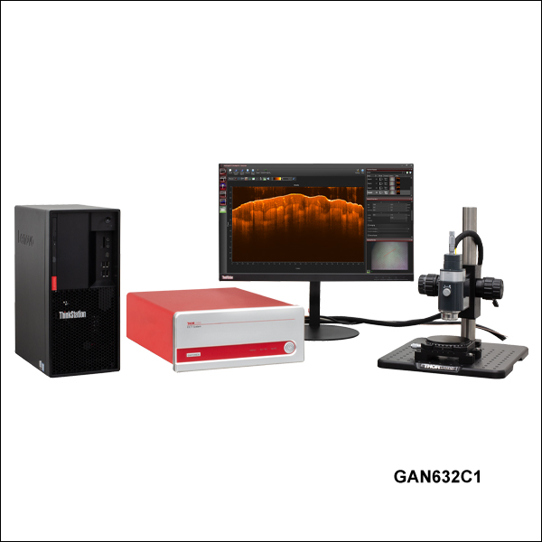
Thorlabs offers five complete, preconfigured Ganymede OCT systems, each of which is fully compatible with all Ganymede Series OCT components. The GAN111C1(/M), GAN312C1(/M), and GAN612C1(/M) systems incorporate an 880 nm superluminescent diode (SLD) and offer high-resolution imaging capability. The GAN332C1(/M) and GAN632C1(/M) systems, which are designed for high-speed imaging applications requiring very high resolution, include three matched SLDs that are coupled together to provide an extended bandwidth light source centered at 880 nm. The Ganymede systems have an A-scan rate of up to 248 kHz and 106 dB sensitivity at 1.5 kHz.
These Ganymede Series preconfigured OCT system configurations are built completely from components sold in sections located lower on this page. Each preconfigured system includes the three OCT system core components (the base unit, a scanning system with its reference length adapter, and a scan lens kit), as well as two optional accessories (scanner stand and translation stage). For more information about a component included in the preconfigured systems, click on the component description in the table below to navigate down to the related section on this page.
For information about these systems or to inquire about custom configurations, please contact oct@thorlabs.com.
| Preconfigured System Included Componentsa | |||||
|---|---|---|---|---|---|
| System Item # | GAN111C1(/M) | GAN312C1(/M) | GAN332C1(/M) | GAN612C1(/M) | GAN632C1(/M) |
| Base Unit | GAN111 | GAN312 | GAN332 | GAN612 | GAN632 |
| Scanning System | OCTG9 (Standard Scanner) | ||||
| Scan Lens Kit | OCT-LK3-BB | OCT-LK3-BB | OCT-LK2-BB | OCT-LK3-BB | OCT-LK2-BB |
| Reference Length Adapter | OCT-RA3 | OCT-RA3 | OCT-RA2 | OCT-RA3 | OCT-RA2 |
| Accessories: Scanner Stand and Translation Stage | Imperial Systems: OCT-STAND (Stand) and OCT-XYR1 (Stage) Metric Systems: OCT-STAND/M (Stand) and OCT-XYR1/M (Stage) |
||||
| Preconfigured System Key Specifications | |||||
|---|---|---|---|---|---|
| System Item # | GAN111C1(/M) | GAN312C1(/M) | GAN332C1(/M) | GAN612C1(/M) | GAN632C1(/M) |
| Center Wavelength | 880 nm | ||||
| Imaging Depth (Air/Water) | 3.4 mm / 2.5 mm | 3.4 mm / 2.5 mm | 1.6 mm / 1.2 mm | 3.4 mm / 2.5 mm | 1.6 mm / 1.2 mm |
| Axial Resolution (Air/Water) | 6.0 µm / 4.5 µm | 6.0 µm / 4.5 µm | <3.0 µm / <2.2 µm | 6.0 µm / 4.5 µm | <3.0 µm / <2.2 µm |
| Lateral Resolution | 8.0 µm | 8.0 µm | 4.0 µm | 8.0 µm | 4.0 µm |
| A-Scan/Line Rate | 1.5 - 20 kHza | 1.5 - 80 kHzb | 5 - 248 kHzc | ||
| Sensitivity (Max)d | 106 dB (at 1.5 kHz) | 102 dB (at 5 kHz) | |||
")
 Zoom
Zoom To be functional, an OCT system build must include a base unit, a scanning system, and a scan lens kit.
| Computer Specificationsa | |||
|---|---|---|---|
| Base Unit Item # | GAN111 | GAN3x2 | GAN6x2 |
| Operating System | Windows® 11 | ||
| Processor | 4 Core, 3.6 GHz | 8 Core, 3.0 GHz | |
| Memory | 16 GB | 32 GB | |
| Hard Drive | 256 GB SSD | 512 GB SSD | |
| Data Acquisition | USB 3.0 | USB 3.0 | CameraLink |
- Flexibility in Imaging Speed with High- and Very-High-Resolution Performance Options
- Systems with up to 248 kHz A-Scan Rate (See Table Below)
- Fully Configurable Trigger for Integration into Larger Experiments
- Analog Input for Combining Other Data Sources with the OCT Signal
- Internal Hardware Diagnostics for Improved Troubleshooting
The imaging performance of any OCT system is largely dependent on the design and components incorporated into the base unit. All of Thorlabs' OCT Base Units include an OCT engine, high-performance computer, pre-installed software, and a software development kit (SDK). For a fully operational system, a scanning system and a scan lens kit (sold separately below) must be purchased with the base unit.
The engines of the Ganymede™ Series OCT Base Units each consist of a superluminescent diode light source, scanning electronics, and a linear CCD array-based spectrometer for detection. The camera built into the Ganymede series base units features both high speed and high sensitivity, providing high A-Scan rates from 1.5 kHz to 248 kHz, with 106 dB sensitivity at 1.5 kHz. The engine and detection components are integrated into a 411.8 mm x 325.0 mm x 143.0 mm (16.21" x 12.80" x 5.63") enclosure.
For synchronization with other experiments, two analog inputs are included on the base units; this allows other data sources to be combined or overlayed with the OCT signal. The OCT base units also feature a fully configurable trigger that is extensively programmable in our ThorImage®OCT software. The trigger can be operated as either an input, responding to external signals, or an output, generating trigger signals. Trigger signals can be sent at the start of each A-, B-, or volume scan, as well as after an arbitrary number of scans.
High-Resolution Imaging Base Units
Integrated into Thorlabs' GAN111, GAN312, and GAN612 base units is an 880 nm superluminescent laser diode (SLD), enabling the units to have high imaging depth and axial resolution in air of 3.4 mm and 6.0 µm, respectively. The GAN312 and GAN612 units allow for A-scan rates of up to 80 kHz and 248 kHz, respectively.
Very-High-Resolution Imaging Base Units
The GAN332 and GAN632 very-high-resolution base units feature Thorlabs' highest resolution OCT imaging capability at a center wavelength of 880 nm. Utilizing three matched superluminescent diodes that are coupled together to provide an extended bandwidth light source, they boast <3.0 μm axial resolution and an imaging depth of 1.6 mm in air. The GAN332 and GAN632 units will allow for A-scan rates of up to 80 kHz and 248 kHz, respectively. These base units are the ideal choice for high-resolution imaging in scattering samples.
| Base Unit Item # | GAN111 | GAN312 | GAN332 | GAN612 | GAN632 |
|---|---|---|---|---|---|
| Description | High Resolution | High Resolution | Very High Resolution | High Resolution | Very High Resolution |
| Center Wavelength | 880 nm | ||||
| Imaging Depth (Air/Water) | 3.4 mm / 2.5 mm | 3.4 mm / 2.5 mm | 1.6 mm / 1.2 mm | 3.4 mm / 2.5 mm | 1.6 mm / 1.2 mm |
| Axial Resolution (Air/Water) | 6.0 µm / 4.5 µm | 6.0 µm / 4.5 µm | <3.0 µm / <2.2 µm | 6.0 µm / 4.5 µm | <3.0 µm / <2.2 µm |
| A-Scan Line Rate | 1.5, 5, 10, & 20 kHz | 1.5, 5, 10, 20, 40, & 80 kHz | 5, 10, 25, 50, 100, 200, & 248 kHz | ||
| Sensitivitya | 96 dB (at 20 kHz) to 106 dB (at 1.5 kHz) | 89 dB (at 80 kHz) 106 dB (at 1.5 kHz) | 84 dB (at 248 kHz) to 102 dB (at 5 kHz) | ||
| Maximum Pixels per A-Scan | 1024 | ||||
| Compatible Scanners | OCTP-900, OCTP-900/M, and OCTG9 | ||||
Click to Enlarge
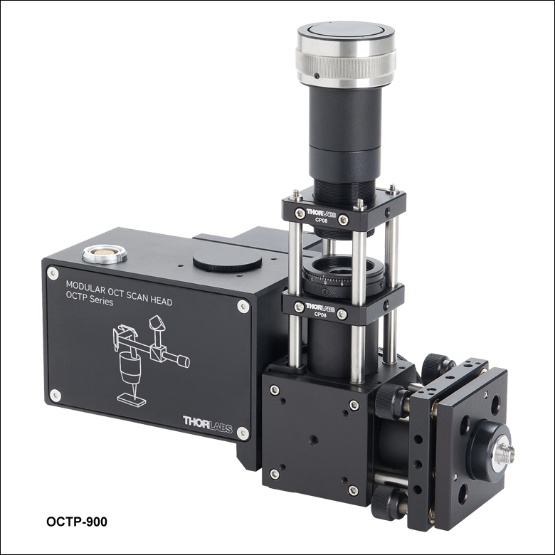
User-Customizable OCT Scanner
Click for Details
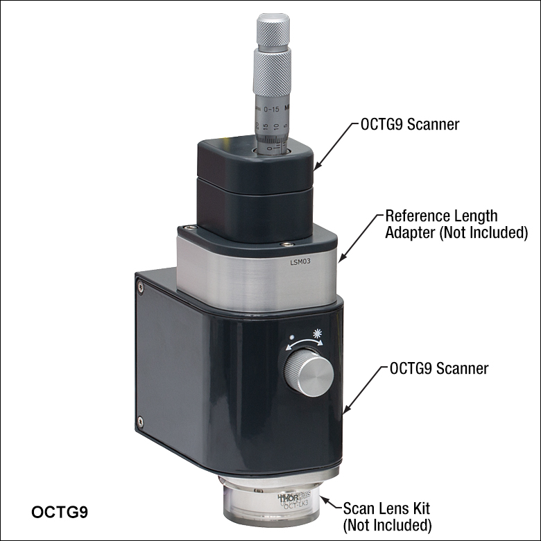
Standard OCT Scanner with Scan Lens Kit and Reference Length Adapter (Not Included)
| Scanner Type | Item # | Compatible Base Units |
|---|---|---|
| Standarda | OCTG9 | GAN111 GAN312 GAN332 GAN612 GAN632 |
| User-Customizable | OCTP-900(/M) |
- Scan an OCT Light Source Beam Across a Sample to Acquire 2D or 3D Images
- Two Available Options
- Standard Scanner for High Stability and Ease-of-Use
- User-Customizable Scanners with Open Construction for Customization of Scan Path
Thorlabs' OCT Scanning Systems are designed to scan the OCT light source beam across a sample
Each scanner contains an OCT interferometer with a sample arm and a reference arm. The reference arm of the OCT interferometer is placed near the sample and housed within the scanning system itself to guarantee the phase stability of the sample arm relative to the reference arm. To account for different sample distances and reflectivities (e.g., while imaging through water), the reference arm path length, as well as the reference arm intensity, is adjustable. To minimize image distortion caused by dispersion, our OCT systems are designed to optically match the reference and sample arm lengths to the greatest extent possible. Dispersion effects from the sample (e.g., imaging through water or glass) can be compensated for using the included ThorImage®OCT software. For customers interested in dual-path setups, either of these scanners can be configured without a beamsplitter; please contact oct@thorlabs.com for more information.
All scanners are equipped with an integrated camera that can obtain real-time en face video of the sample during OCT measurements when used with our ThorImageOCT software (see the Software tab for details). Illumination of the sample is provided by a ring of user-adjustable white light LEDs around the exit aperture of each scanner.
To be functional, an OCT system build must include a base unit, a scanning system, and a scan lens kit.
Standard Scanner
The OCTG9 Standard Scanner is ideal for imaging applications that require a stable, easy-to-operate setup. The entire design of the standard scanner is contained within a rugged, light-tight housing that minimizes the risk of misalignment. For precise measurements and fine adjustments of the reference arm length, a micrometer screw is located at the top of the standard scanner. A reference length adapter, which must be purchased separately, is required for this scanner.
User-Customizable Scanner
The OCTP-900(/M) User-Customizable Scanner is designed with an open construction to enable easy customization of the optical beam path using Thorlabs' standard optomechanical components. This scanner features SM1 (1.035"-40) ports and 4-40 tapped holes at several locations that allow mounting of SM1-threaded or 30 mm cage-compatible components, respectively. The scan lens port is directly compatible with either M25 x 0.75 or SM1-threaded components, and can be converted to other thread standards, such as RMS (0.800"-36) via our selection of thread adapters. Additional scanning and non-scanning optical input/output ports are available for integration of a laser for fluorescence excitation or additional sample illumination.
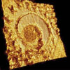
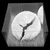
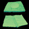
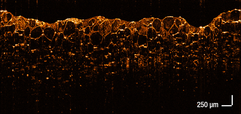
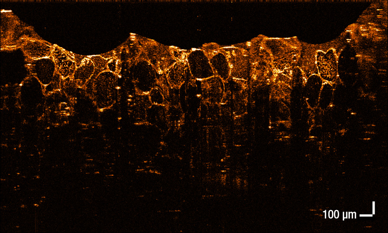
The cross-section images below of an apple were taken with the OCT-LK2-BB and OCT-LK3-BB scan lens kits using Ganymede™ Series OCT systems. Choose a scan lens kit that provides the right resolution and focal length for your application.
(Used with the Previous-Generation GAN611)
Click to Enlarge
Magnification: 5X
Scan Region: 6 mm x 2.9 mm
Lateral Resolution: 8 µm
(Used with the Previous-Generation GAN621)
Click to Enlarge
Magnification: 10X
Scan Region: 3 mm x 1.9 mm
Lateral Resolution: 4 µm
- Telecentric Scan Lenses Provide a Flat Imaging Plane
- Lenses AR Coated for 800 - 1100 nm
- Scan Lens Kits Include
- Telecentric Scan Lens
- Illumination Tube
- IR Card
- Calibration Target
- Dispersion Compensation Set
 To be functional, an OCT system build must include a base unit, a scanning system, and a scan lens kit.
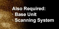
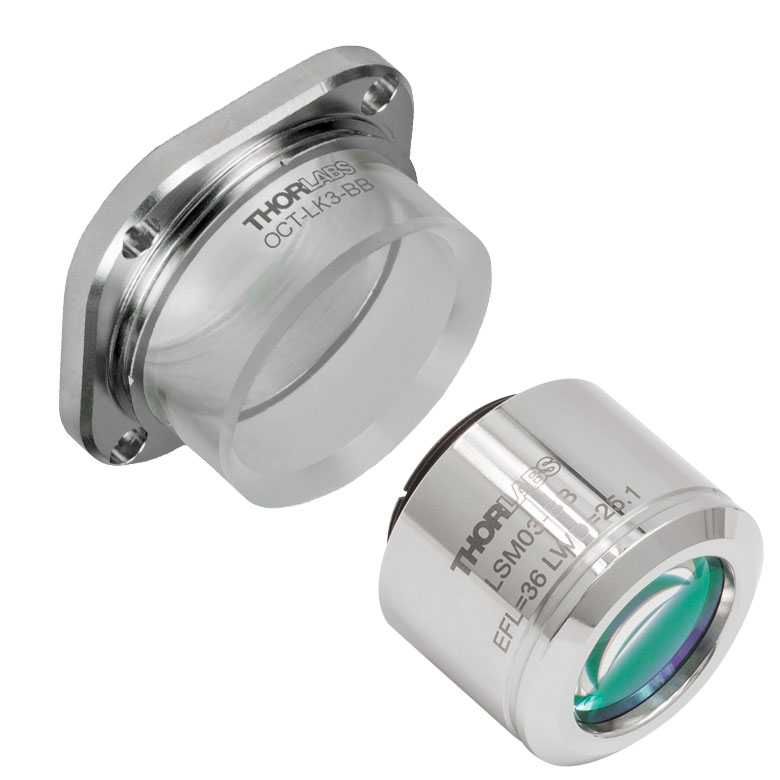
Thorlabs' Scan Lens Kits enable easy exchange of scan lenses in an OCT system, providing the flexibility to tailor imaging resolution or working distance for each application. Based on our line of OCT telecentric scan lenses, these lens kits minimize image distortion without extensive post-image processing and maximize coupling of the light scattered or emitted from the sample surface into the detection system. As seen in the table below, we offer three scan lens kits compatible with the standard (Item # OCTG9) and user-customizable (Item # OCTP-900) scanners.
Each kit includes a telecentric scan lens, illumination tube, IR card, and calibration target. The included illumination tube serves as a light guide that channels light from the LED illumination ring down to the sample area. The IR card and calibration target are provided for calibration of the scanning mirror and lens kit, ensuring the best image quality when swapping between scan lenses.
| Scan Lens Kit Item # | OCT-LK2-BB | OCT-LK3-BB | OCT-LK4-BB |
|---|---|---|---|
| Click Image to Enlarge | 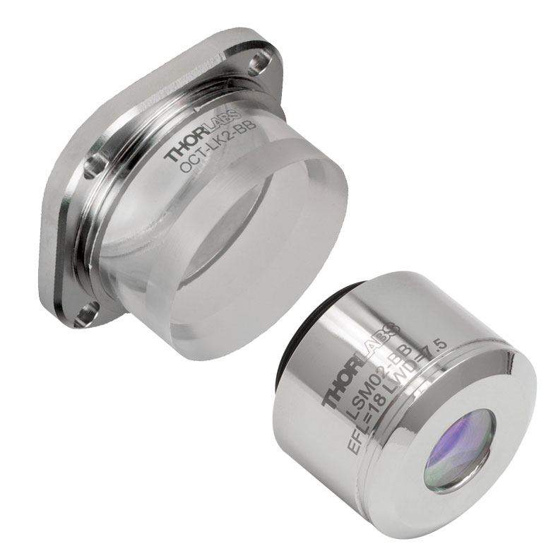 |
 |
 |
| Design Wavelength | 880 nm / 900 nm / 930 nm / 1060 nm | ||
| Compatible Scanner | OCTG9 (Standard) or OCTP-900 (User-Customizable) | ||
| Lateral Resolutiona | 4 µm | 8 µm | 12 µm |
| Effective Focal Length | 18 mm | 36 mm | 54 mm |
| Working Distance | 3.4 mm (with Tube)b 7.5 mm (without Tube) |
24.9 mm (with Tube)b 25.1 mm (without Tube) |
41.6 mm (with Tube)b 42.3 mm (without Tube) |
| Field of View | 6 mm x 6 mm | 10 mm x 10 mm | 16 mm x 16 mm |
| Lens Threading | M25 x 0.75 | M25 x 0.75 | M25 x 0.75 |
")
 Zoom
Zoom| Item #a | Compatible Scan Lens Kit |
|---|---|
| OCT-RA2 | OCT-LK2-BB |
| OCT-RA3 | OCT-LK3-BB |
| OCT-RA4 | OCT-LK4-BB |
- Arm Adapters for Matching Reference Path Length to the Sample Path Length
- Use Multiple Reference Adapters for Rapid Switching Between Scan Lens Kits
- Must be Purchased with Standard Scanner (Item # OCTG9)
These adapters adjust the reference arm path length within the OCTG9 Standard Scanner to match the sample path length of the scan lens used. Choose from three options that are compatible with the scan lens kits sold above. Reference length adapters also enable the user to quickly swap between different scan lens kits without going through extensive adjustments during each switch. The table to the right provides a compatibility list to help select the appropriate reference adapters.
")
- Sample Z-Spacers Position Scanner at Optimal Working Distance From Sample
- Ring (Air) and Immersion (Liquid) Z-Spacer Available
Thorlabs offers both ring and immersion style sample Z-spacers that enable optimal positioning of a scanning system relative to the sample. The OCT-AIR3, OCT-IMM3, and OCT-IMM4 Z-Spacers feature knurled rings that allow the spacing distance to be adjusted and locked in place for increased stability. Several Z-spacer options are available; please see the table below for compatibility with our scanners and lens kits.
Our ring-style Z-spacer provides a distance guide between the scanner and sample. The sample is in contact with the ring-shaped tip of the spacer and should only be used when air is the scanning medium. In contrast, our immersion spacers are equipped with a glass plate that contacts the sample surface within the scanning area. Unlike the ring-style spacer, immersion spacers enable access to samples contained within a liquid environment while also providing sample stabilization. Better index matching and a tilted glass plate also help reduce strong back reflections from the sample surface and enhances the contrast of the image.
| Item # | Type | Adjustable | Adjustment Range | Lockable | Compatible Scanner |
Compatible Scan Lens Kit |
|---|---|---|---|---|---|---|
| OCT-AIR3 | Ring (Air) | Yes | +3.5 mm / -1.0 mm | Yes | OCTG9 OCTP-900(/M) |
OCT-LK3-BB |
| OCT-IMM3 | Immersion | Yes | +3.4 mm / -1.1 mm | Yes | ||
| OCT-IMM4 | Immersion | Yes | +1.0 mm / -17.0 mm | Yes | OCT-LK4-BB |
")
 Zoom
Zoom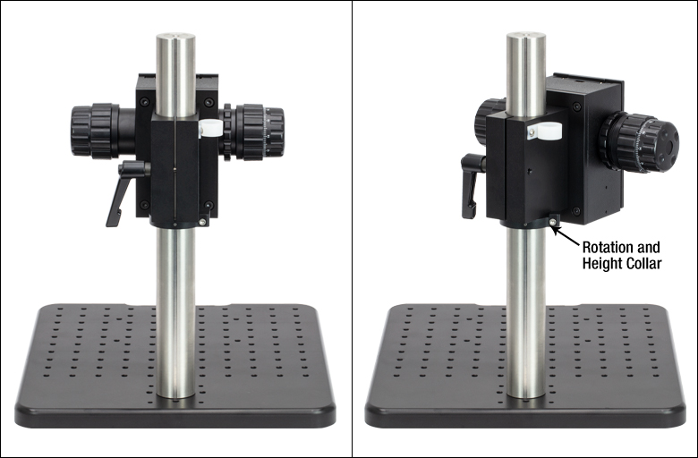
Click for Details
The focus block can be rotated 45° to move the scanner head away from the sample.
- Recommended Stand for Mounting Standard or User-Customizable Scanners
- Focus Block with Coarse/Fine Z-Axis Travel on Ø1.5" Stainless Steel Post
- 12" x 14" (300 mm x 350 mm) Aluminum Breadboard with 1/4"-20 (M6) Tapped Holes
For convenient mounting of our Standard or User-Customizable Scanners, we offer a scanner stand that is ideal for use in vibration-sensitive studies such as angiography. It consists of a post-mounted focus block with knobs that provide both coarse (40 mm/rev) and fine (225 µm/rev) z-axis travel. A rotation and height collar underneath the focus block allows it to rotate 45° in order to move the scanner head away from the sample to make adjustments.
The focus block attaches to a 12" x 14" (300 mm x 350 mm) aluminum breadboard via the included Ø1.5" post. The aluminum breadboard has side grips and rubber feet for easy lifting and transportation. There is an array of 1/4"-20 (M6) tapped holes for mounting optomechanics. Four extra 1/4"-20 (M6) tapped holes allow the mounting of the OCT-XYR1 Translation Stage (sold below) to the OCT-STAND and the OCT-XYR1/M Translation Stage to the OCT-STAND/M directly underneath the scan lens. A 1/4"-20 (M6) counterbore is also provided for securing the Ø1.5" post.
")
 Zoom
ZoomClick to Enlarge
The cover plate is removable for access to tapped holes and the SM1-threaded central hole.
| Specifications | |
|---|---|
| Horizontal Load Capacity (Max) | 10 lbs (4.5 kg) |
| Mounting Platform Dimensions | Ø4.18" (Ø106 mm) |
| Stage Height | 1.65" (41.8 mm) |
| Linear Translation Range | 1/2" (13 mm) |
| Travel per Revolution | 0.025" (0.5 mm) |
| Graduation | 0.001" (10 µm) per Division |
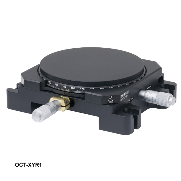
- Optional Translation Stage with 0.5" (13 mm) of XY Travel and 360° Rotation
- Includes Cover Plate for Sample Mounting
- Can Mount Optomechanics by Removing Cover Plate
Precise translation and rotation are often required for optimal positioning of a sample before and during OCT imaging. The OCT-XYR1(/M) is an XY linear translation stage with a rotating platform and solid plate for sample mounting and easy cleaning. The OCT-XYR1 or OCT-XYR1/M stage can be secured to the OCT-STAND or OCT-STAND/M, respectively, using the 1/4" (M6) counterbores at the corners. The top plate is removable for access to 4-40, 8-32 (M4), and 1/4"-20 (M6) tapped holes and an SM1-threaded (1.035"-40) central hole for mounting optomechanical components. The XYR1A Solid Sample Plate can be purchased separately as a direct replacement for the top plate.
The X and Y micrometers offer 1/2" (13 mm) of travel with graduations every 0.001" (10 µm). The stage's rotation and translation can be freely changed without compromising the stability of attached components. An engraved angular scale along the outer edge of the stage's rotating platform allows the user to set the angular orientation of the stage, which can then be fixed using the 5/64" (2 mm) hex locking setscrew. Locking the rotation of the stage does not prevent XY translation using the actuators.