 Products Home / Drivers & Mounts / Optoelectronics Mounts / Butterfly Optoelectronic Mounts / Butterfly Laser Diode Mounts
Butterfly Laser Diode Mounts

- Zero Insertion Force (ZIF) Sockets
- Easy Integration with Thorlabs’ Current & TEC Controllers
- Compatible with One & Two Port Devices
LM14S2
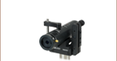
Universal 14-Pin Butterfly Laser Diode Mount
LM14S2-UA
Additional User-Configurable Pin-Out Card
(One Included with LM14S2)
LM14S2 Shown with a Two-Port
Electro-Optic Device


Please Wait

| Feature Comparison of Butterfly Laser Mounts | |||
|---|---|---|---|
| Item # | LM14S2a | LM14TSb | CLD1015c |
| Supports Type 1 (Anode GND) |  |
|
|
| Supports Type 2 (Anode GND) | |
|
|
| Supports Bias-T Connection | |
- | - |
| Supports Thorlabs ULN Laser | - | |
- |
| Integrated Laser-Case-Temperature Stabilization | - | |
- |
| DB9 Input for Thorlabs' Laser Driver | |
|
-c |
| DB9 Input for Thorlabs' Laser-Chip TEC Controller | |
|
-c |
| Dedicated ULN FBG TEC Controller Input | - | |
- |
Features
- Laser Diode Mount for 14-Pin Butterfly Packages
- Zero Insertion Force (ZIF) Mounting Socket
- Type 1, Type 2, Type 2 with Bias-T, and User-Defined Pinout Configurations
- LED Indicates When Laser is Enabled
The LM14S2 Universal 14-Pin Butterfly Laser Diode Mount is designed for use with lasers, optical amplifiers, and two-port electro-optic devices in a 14-pin type 1, 2, or 2 with bias-T butterfly package. The top surface has heat sink fins and a recessed region to mounta the laser diode, resulting in a low profile package with a temperature coefficient of 3 °C/W. The LM14S2 also includes a laser diode TEC lockout featureb that disables the laser when the TEC controller is not active. The LM14S2 supports maximum laser and TEC currents of 5 A each. In order to utilize the TEC controller, the laser must have an integrated thermoelectric cooler (TEC) or thermistor sensors. This mount also features a zero insertion force (ZIF) socket, a remote safety interlock connection, and an LED to indicate that the laser diode is enabled.
The LM14S2 eliminates the restriction of fixed-pin configuration mounts by using exchangeable configuration cards that plug into a connector located on the bottom of the mount. Included with the LM14S2 is a card that provides compatibility with both type 1 pump laser diodes and type 2 telecom laser diodes. For the pin diagrams that correspond to these types, please refer to the Pin Diagrams tab. In addition, a second card (Item # LM14S2-UA) is also included. The LM14S2-UA is a user-configurable card designed to allow custom wiring of the mount. Additional LM14S2-UA user-configurable cards are available separately. Please note that even with an LM14S2-UA, only anode-grounded diodes can be used with the LM14S2 butterfly laser mount.
In addition to the configurable pinout feature, a bias-T adapter is included, allowing for RF modulation of butterfly lasers specifically designed with this capability. It features a female SMA connector for an RF source up to 500 MHz, and is designed for lasers with a type 2 pin configuration including an internal bias-T and built-in blocking inductor. For more details on the pin assignments, please refer to the Pin Diagrams tab as well as the spec sheet for the specific laser diode to be used. Please note that Thorlabs' butterfly package laser diodes are not compatible with the bias-T adapter.
The LM14S2 is pin-for-pin compatible with all of Thorlabs' benchtop laser diode and TEC controllers, and most of our platform laser and TEC controllers as well, eliminating the need for custom-made interface cables.
| Item # | LM14S2 |
|---|---|
| Maximum Laser Current | 5 A |
| Polarity of Laser Diode | Anode Ground |
| Polarity of Monitor Diode | Floating |
| Maximum TEC Current | 5 A |
| Temperature Sensor | Thermistora |
| Temperature Rangeb | 0 to 70 °C |
| Temperature Coefficient of Heat Sink | 3 °C/W |
| Dimensions | 3.50" x 3.50" x 1.31" (88.9 mm x 88.9 mm x 33.3 mm) |
| Modulation (Bias-T Adapter) Specificationsc | |
| RF Modulation Frequency | 100 kHz to 500 MHz |
| RF Input Connection | SMA |
| RF Input Impedance | 25 Ω |
| RF Power (Max) | 200 mW or Limit of Laser Diode |
Laser Diode Connector
D-type Female
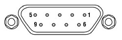
| Pin # | Signal |
|---|---|
| 1 | Interlock and Status Pin (LDC Specific) |
| 2 | Photodiode Cathode PDC |
| 3 | Laser Diode Anode LDA |
| 4 | Photodiode Anode PDA |
| 5 | Interlock and Status Return |
| 6 | Laser Diode Voltage (-) VLD(-) |
| 7 | Laser Diode Cathode LDC |
| 8 | Not Used |
| 9 | Laser Diode Voltage (+) VLD(+) |
Bias-T Modulation Adapter*
SMA Female
*RF input for modulation with an external source from 100 kHz to 500 MHz.
TEC Connector
D-type Male
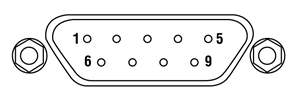
| Pin # | Signal |
|---|---|
| 1 | TEC Lockout (+) |
| 2 | +Thermistor TH+ |
| 3 | -Thermistor TH_GND |
| 4 | TEC (+) |
| 5 | TEC (-) and TEC Lockout (-) |
| 6 | Not Used |
| 7 | Not Used |
| 8 | Not Used |
| 9 | Not Used |
Pin Assignment of the 14-pin Sockets
The included LM14S2-US custom configuration card can be used for any other pin configuration. This card is also available separately below.
| Pin to Connector Configuration for Type 1 | Pin to Connector Configuration for Type 2 | Pin to Connector Configuration for Type 2 with Bias-T |
|||
|---|---|---|---|---|---|
 Click to Enlarge |
 Click to Enlarge |
 Click to Enlarge |
|||
| 1 | TEC Anode | 1 | Thermistor Ground | 1 | Thermistor Ground |
| 2 | Thermistor | 2 | Thermistor | 2 | Thermistor |
| 3 | PD Anodea | 3 | LD Cathode | 3 | LD Cathode |
| 4 | PD Cathodea | 4 | PD Anode | 4 | PD Anode |
| 5 | Thermistor Ground | 5 | PD Cathode | 5 | PD Cathode |
| 6 | N.C. | 6 | TEC Anode | 6 | TEC Anode |
| 7 | PD Cathodea | 7 | TEC Cathode | 7 | TEC Cathode |
| 8 | PD Anodea | 8 | Case | 8 | Case |
| 9 | LD Cathodeb | 9 | Case | 9 | Case |
| 10 | LD Anode, Ground | 10 | N.C. | 10 | N.C. |
| 11 | LD Cathodeb | 11 | LD Anode | 11 | LD Anode |
| 12 | N.C. | 12 | N.C. | 12 | Modulation Inputc |
| 13 | LD Anode, Ground | 13 | LD Anode | 13 | LD Anode |
| 14 | TEC Cathode | 14 | N.C. | 14 | N.C. |
Click to Enlarge
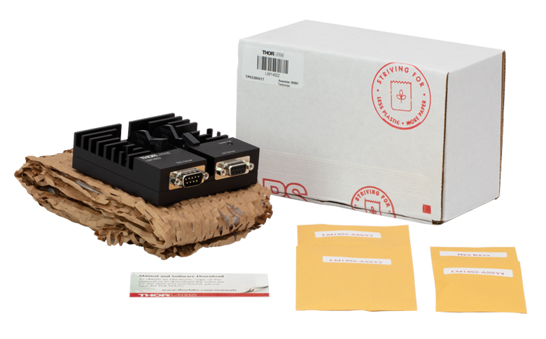
Figure 4.2 LM14S2 Packaging

| Table 4.1 Products with Re-Engineered Packaging | ||
|---|---|---|
| Item # | % Weight Reduction |
CO2-Equivalent Reductiona |
| LM14S2 | 21.52% | 30.10 kg |
Smart Pack
- Reduce Weight of Packaging Materials
- Increase Usage of Recyclable Packing Materials
- Improve Packing Integrity
- Decrease Shipping Costs
Thorlabs' Smart Pack Initiative is aimed at waste minimization while still maintaining adequate protection for our products. By eliminating any unnecessary packaging, implementing packaging design changes, and utilizing eco-friendly packaging materials for our customers when possible, this initiative seeks to improve the environmental impact of our product packaging. Products listed in Table 4.1 are now shipped in re-engineered packaging that minimizes the weight and the use of non-recyclable materials.b As we move through our product line, we will indicate re-engineered packages with our Smart Pack logo.
| Posted Comments: | |
HB Shin
(posted 2025-03-06 17:36:23.313) Dear, We are using FPV785M (type I), LM14S2 butterfly Laser Diode Mount, LDC210C(1A), TED200C. When the butterfly Laser Diode is connected, LDC210C is ready, but the "NOT CONNECTED" light is on at TED200C. Is it right that the "TEC Lockout (+)" at the TEC Connector D-type Male is disconnected from any of the butterfly laser diode pins? ksosnowski
(posted 2025-03-06 03:31:29.0) Hello, thanks for reaching out to us. The interlock lines do not directly interface with the TEC or LD drive currents, these only serve as a potential fault signal to the controllers and to power the laser status indicator on the mount. If the “OPEN” indicator is present on the driver, this means the circuit cannot reach the desired output current within the driver's compliance voltage range, and shows the resistance of the circuit is too high. This commonly results if a connector is loose or disconnected. With LM14S2 and you should also ensure the circuit board is installed in the correct orientation since Type 1 and Type 2 place the TEC differently which could result in an OPEN TEC error. I have reached out directly to help troubleshoot further. Stefano Taccheo
(posted 2024-12-18 12:05:13.247) We recently bought a Thorlabs butterfly 785 nm diode laser and we are using on your LN14S2 mount.
We are modulating the input current (from the cable) up to 300 kHz but the laser output shows a far slower modulation of a few kHz.
We cannot use bias-T (to high frequency).
Is any way to bypass your mount impedance and directly modulate the lasers up to 300 kHz by using direct modulation of the input current?
Best regards
Stefano Taccheo Shiva Vikram Bhagavatula
(posted 2024-07-31 13:05:26.73) The modulation of the laser diode current (for changing wavelength) with the bias tee option is highly sensitive to the smallest change in the position of the SMA cable. How do you ensure repeatability of the connection? The bias tee sits on top of the laser diode pins and the contact between the two is influenced by the weight, tension of the SMA cable connecting to the other end of the bias tee and its position. ksosnowski
(posted 2024-08-09 05:23:43.0) Hello Shiva, thank you for reaching out to us. The ZIF socket and the two securing screws should provide enough positive contact force to keep these pins in reliable contact. Securing the LM14S2 to the table through the mount's counterbores as well as using a cable strap like our CS1 may help with further preventing any connection issues due to strain in the cables. If any components like the socket's screws are lost we can help you get replacements. I have reached out directly to discuss your application in further detail. user
(posted 2024-06-11 13:18:28.213) Dear Thorlabs,
We are using LM14S2 and ITC4001. When operating the diode laser, the center frequency is too unstable. It's fluctuating around 100MHz. Is there a suspected cause for this? It seems we could deliver our situation in more detail through email. ksosnowski
(posted 2024-06-25 05:35:48.0) Thanks for reaching out to us. The stability of the laser wavelength can strongly depend on the drive current and temperature stability, as well as the presence of any backreflections. With our ITC4001 the drive current noise is quite low however achieving good temperature stability relies on finding the best PID coefficients for your exact system and operating points. Our ITC4001 manual covers how to tune the PID of the system and I recommend using the temperature driver's software to better observe any fluctuations in the temperature over time with a plot display while PID tuning. I have reached out directly to discuss your application in further detail. Iko Ben-Giat
(posted 2024-06-06 21:19:16.707) Hello,
We have encounter with few problems using the LM14S2 (used together with TED4005 and 3rd party Laser driver), which we hope you can help us with.
1. Using the custom Pin out configuration card, we saw that temp. tend to have higher temp. fluctuations up to +/- 0.005 degrees, while without USB it is with the spec of the TED4005 +/- 0.001 degrees. Are there any instruction for the wiring of this card (i.e. AWG, type of wiring etc.)
2.When using TYPE I setting there is a puzzling short between Pin 10 which supposed to be Anode and the case ground (pin 13) - even when using TL PN780PN laser? Is there other pin out or is ok?
Appreciate prompt response
Iko Ben Giat - Chief Product & Engineering
iko@tera.group jpolaris
(posted 2024-06-07 01:20:26.0) Thank you for contacting Thorlabs. I have reached out to you directly to get clarification on your issue with temperature fluctuation. For wiring the configuration card, ideally, a solid 26 - 30 AWG insulated wire would be used for making the connections. Regarding part (2) of your message, yes, for Type 1 butterfly packages, the connections you've described are normal. I have sent you a pin diagram that should help clarify these connections. Todd Harris
(posted 2024-04-19 10:48:59.5) Please provide a torque specification for torqueing down the four (4) #2-56 screws that secure the 14-pin butterfly package to the heat sink. ksosnowski
(posted 2024-04-22 03:21:34.0) Hello Todd, thanks for reaching out to Thorlabs. For the LM14S2 and our butterfly diodes, a torque of 10~20oz·in (0.07~0.14N·m) is recommended for securing the screws. Shiva Vikram B
(posted 2023-08-09 09:58:19.7) We want to purchase the modulator bias tee adapter pcb separately. ksosnowski
(posted 2023-08-18 04:17:05.0) Hello Shiva, thanks for reaching out to Thorlabs. Yes we can offer the bias tee adapter PCB component separately as a special quote in case it's been lost or damaged. In these cases we would recommend you to contact techsupport@thorlabs.com directly, and I've reached out to discuss your application further detail. user
(posted 2023-05-18 17:18:29.64) Hello! We want to use LM14S2 mount with LDC8005 and TED8020, but we find that the pin configurations of LM14S2 and LDC8005 are different, the pin3 of LM14S2 is Laser Diode Anode and pin3 of LDC8005 is Laser Diode Ground, while the pin8 of LM14S2 is Not Used and the pin8 of LDC8005 is Laser Diode Anode. Do I need to swap the connection of pin3 and pin8 of the cable when using them together? cdolbashian
(posted 2023-05-26 12:55:51.0) Thank you for reaching out to us with this inquiry. As the butterfly diodes are Anode grounded, the pin 3 and pin 8 have identical electrical paths. You shouldn't need to swap any connectors. I have contacted you directly to discuss this in more detail. user
(posted 2022-04-15 10:19:25.907) Hello! Could you please tell me if the LM14S2 is thermal vacuum compatible? cdolbashian
(posted 2022-04-20 04:40:50.0) Thank you for reaching out to us with this inquiry. I have reached out to you directly to discuss the specific vacuum environment in which you are intending to place this device. Ben Griffiths
(posted 2022-02-02 10:30:38.233) Hi, I see that the bias-t provided in the LM14S2 is spec'd to 500 MHz. Ideally I would like to drive an RF signal at several GHz, do you offer a bias-t that could handle this higher rate to fit this mount? ksosnowski
(posted 2022-03-02 11:44:48.0) Thanks for reaching out to Thorlabs. Unfortunately we currently do not offer any drivers or mounts that can achieve these higher speeds. In the past, we have recommended using drivers and mounts offered by AV Tech (which is not affiliated with Thorlabs in any way). An alternative option to modulate at higher frequencies is to use an external source such as a LiNbO3 EO modulator. I have reached out directly to discuss your application further. YLohia
(posted 2021-07-09 02:54:54.0) Hello, thank you for your feedback. I have posted your suggestions on our internal engineering forum for consideration as a future product. Wieslaw Jasiewicz
(posted 2020-11-14 10:23:38.04) Hi,
I can not find main PCB wiring and parts (U1) specification within LM14S2 documents.Would it be possible to get it as it is necessary for our application?
Regards
Wieslaw asundararaj
(posted 2020-11-17 08:24:02.0) Thank you for contacting Thorlabs. The PCB design and circuitry are considered proprietary and typically, we are not able to share this. I will reach out to you directly regarding your application. Ashwin Vijayasai
(posted 2020-02-27 04:55:08.153) Do you have a Butterfly Laser Diode Mount version where external case temperature can be controlled. Newport has one item that can control external case temp. from -5C to 85C. LDM-4984T
https://www.newport.com/f/telecom-laser-diode-mounts asundararaj
(posted 2020-02-27 04:12:04.0) Thank you for your feedback. At the moment, we do not have a butterfly laser diode mount with external case temperature control. I have added this idea to our internal product forum for discussion to offer this at a future time. Matthew Majewski
(posted 2019-09-26 22:07:42.733) Hello,
I understand that the bias-T adapter supplied will only work with diodes that have the correct internal circuity, but my question is if it would be possible to use your laser diode bias-T PCB component to externally wire up a modulation input for other diode types? asundararaj
(posted 2019-10-02 11:05:27.0) Thank you for your Feedback. To use the Bias-T adapter with other configurations of diodes in a Butterfly package, you can manually configure the LM14S2-UA to suit the pin configurations of your diode. HYUNJONG CHOI
(posted 2019-08-27 17:56:47.8) Nice to meet you.
I'm try to find the evaluation board of thorlabs CW laser "SFL1550P". In the manual of SFL1550P, LM14S2 will be used for mounting the laser SFL1550P. Is it mean that LM14S2 can be used for the evaluation board of SFL1550P? Please reply. Thank you
Your sincerely,
Choi YLohia
(posted 2019-08-27 09:25:51.0) Hello Choi, thank you for contacting Thorlabs. The LM14S2 is intended to serve as a proper mount for butterfly laser diodes and can be used for nominal testing of the SFL1550P. I have reached out to you directly to gather more details about your application and requirements. bsvikram
(posted 2017-05-23 01:24:29.873) Hi, We want to use bias-t to modulate the current of a type -1 diode (SFL 1550S). But the manual says that the bias tee is for type-2 diodes only. How can we modulate type -1 diodes at high frequencies. We also have CLD 1015, but it is also limited in modulation frequency range. nbayconich
(posted 2017-06-09 09:33:29.0) Thank you for contacting Thorlabs. The bias-T adapter in the LM14S2 is only compatible with Type 2 Telecom Laser Diodes. Type 2 telecom butterfly diodes are designed specifically to be modulated by a bias-T RF circuit. The type 1 butterfly diode packages do not have the proper circuitry in order to be modulated in a bias-T circuit.
Some alternative options to modulate your Type butterfly diodes at higher frequencies is to use an external modulating source such as a LiNbO3 EO modulator which can modulate up to 40 Gb/s .
Several of our Laser Diode current drivers can directly modulate the type 1 butterfly diode mounts through the LM14S2. For example the ITC series controllers can directly modulate from DC to 150Khz. A Techsupport representative will contact you directly with more information. savin.saju
(posted 2017-03-07 21:59:26.173) dear Sir ,
LM14S2 is used for 14 pin butterfly package. Currently, there are 10 pin butterfly package laser.
Do you have laser mount for 10-pin butterfly package???
please reply jlow
(posted 2017-03-08 09:01:37.0) Response from Jeremy at Thorlabs: We do not currently have a 10-pin butterfly mount. I will contact you regarding a custom solution. schdingo
(posted 2014-11-18 15:00:38.487) Dear Sir or Madam,
what is the maximum heat capacity of the LM14S2?
Sincerely jlow
(posted 2014-12-10 05:07:40.0) Response from Jeremy at Thorlabs: We do not have a spec on the maximum heat capacity but it is estimated to be around a few W. We will contact you directly to discuss more about suitability of the mount with your application. emsia
(posted 2013-11-19 10:52:41.403) Dear Sir/Madam,
I am using ILX LDC to control my laser mounted on LM14S2. Everything works perfectly except when the laser is on, the LED does not turn on. The intelock is on bypass mode.
The pin 1 os LD is connected to intrlk of the ILX LDC and pin 5 to the ground.
any suggestions would be appreciated.
Thank you jlow
(posted 2013-11-19 09:23:30.0) Response from Jeremy at Thorlabs: The LED indicator needs a certain amount of current (5-10mA) to turn on. We will get in touch with you directly to troubleshoot this. thomas.chassagne
(posted 2013-07-02 15:29:14.367) Hi, I would like to use the LM14S2 with the TED200 TEC controller and an external electronic board that command the bias current.
In order to disable the Status and the Interlock function, Should I switch the TEC Lock button to "Bypass" ?
In the Operating Manual, it's said that a resistor should be used to limit the curent into the PIN1 to between 5. Thus, if I connect the "driver" side of the resistor to 5V, I should use a 500Ohm resistor and connect the PIN5 to the ground ?
Thanks, Thomas tcohen
(posted 2013-07-11 16:20:00.0) Response from Tim at Thorlabs to Thomas: Thank you for contacting us. Yes, it should be switched to Bypass. You can use that resistance but you may use slightly higher as the current should be limited to a maximum of 10mA. mlaroton
(posted 2013-03-14 10:48:56.47) Hi, I would like to use the LM14S2 mount with the FLD5F10NP-A Modulator-integrated DFB laser.
In this laser, the case ground is the laser cathode.
I wonder if I can still use your mount; do I need a non-standard Adapter Card? or does this feature prevents me to use your mount at all? Thanks, Miguel. tcohen
(posted 2013-03-14 13:22:00.0) Response from Tim at Thorlabs: Physically it appears as if your modulation connection opposite to the pins would interfere with our package designed for a 14pin butterfly. Even if this were to fit however, and a custom configuration card LM14S2-UA was to be used, the LM14S2 is suitable only for anode-grounded diodes. jjurado
(posted 2011-06-15 11:29:00.0) Response from Javier at Thorlabs to zhemin.cai: Thank you very much for contacting us. We can certainly provide reference drawings that you might be able to use in order to determine whether the LM14S2 will work with your pigtail. Please contact us at techsupport@thorlabs.com, and we will gladly assist you. zhemin.cai
(posted 2011-06-10 06:55:59.0) Dear Sir/Madam,
I am wondering is that possible to get the mechanical drawing for the LM14S2? Becasue we
want to use it to hold a long butterfly package,
I want to check if it is fit in or not.
Cheers.
Zhemin.Cai tor
(posted 2011-01-04 14:35:52.0) Response from Tor at Thorlabs to mhafiz.abakar: Thank you for your interest in our LM14S2. This mount is compatible with our LDC8040 and TED8040 via compatible connector cables, http://www.thorlabs.com/NewGroupPage9.cfm?ObjectGroup_ID=895 . We recommend a CAB400 to connect to the LDC and a CAB420-15 to connect to the TED. mhafiz.abakar
(posted 2010-12-28 21:23:58.0) Is this laser diode mount suitable to be used with LDC8040 and TED8040 on a pro800 mainframe. thanks. apalmentieri
(posted 2010-02-10 08:58:39.0) A response from Adam at Thorlabs to serefocal: The LM14S2 is designed to be used with a temperature controller, like the TED200C. It has the ability of controlling the temperature between 0 and 70 degrees C. The temperature coefficient of the heat sink is 3 degreeC/W. I will email you directly to answer any other questions you may have. serefocal
(posted 2010-02-10 10:03:30.0) Dear Sir/Madam:What is the "LM14S2 Butterfly Laser Diode Mounts"s Heat Dissipation Capacity?
May I learn?
Thanks... klee
(posted 2009-09-09 10:44:30.0) A response from Ken at Thorlabs to yuhengc: An applications engineer will contact you directly to discuss about the problem. yuhengc
(posted 2009-09-09 09:24:44.0) Dear Sir/Madam:
We are using LM14S2. Recently we found the current waveform of DFB LD was not stable. The current drive seems to be OK. Since it is new one and I tested with two simulated diode in series. There was no problem. But when I connected to the LD. The current waveform ( monitored from the current feedback)was not constant. Even worst, after a period of fluctuation, it kept decreasing and finally went down to zero. Sometime, if I switched off the driver and powered up again. The current recovered. The LD is the NEL with a little difference layout of pin to type two laser. I am using type 2 configuration card with pin12 connected as the instruction from the manual. What ,do you think, is the reason? |