 Products Home
Mounted LEDs
- UV, Visible, IR, and Mid-IR Models Available
- Optimized Heat Management Results in Stable Output
- Internal SM1 (1.035"-40) Threading
- Collimation Adapters Available Separately
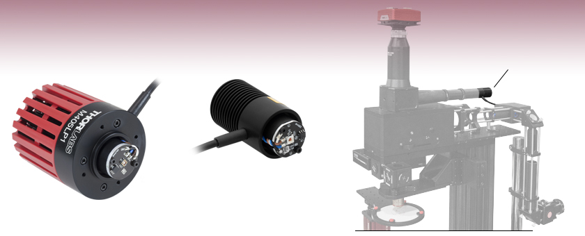
M405LP1
405 nm,
1200 mW Minimum Output Power
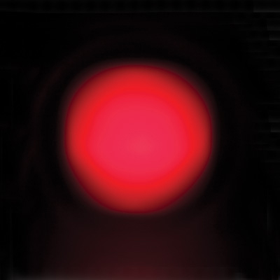
M660L4
660 nm,
940 mW Minimum Output Power
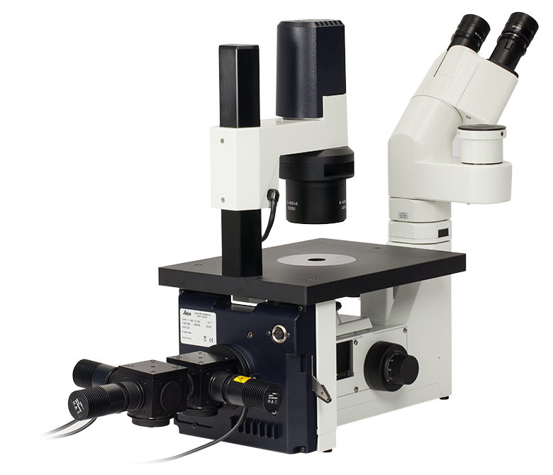
Mounted LED used as a Light Source for a DIY Cerna® Microscope


Please Wait
- We offer suggestions for how to collimate most of our LEDs. Click on the info icons (
 ) for details. The Collimation tab provides additional information on collimating an LED.
| Webpage Features | |
|---|---|
| Clicking this icon opens a window that contains specifications, mechanical drawings, and information about driver and collimator compatibility. | |
 |
Clicking this icon allows you to download our standard support documentation. |

Click to Enlarge
Figure 1.1 The MWWHL4 LED and COP1-A microscope collimation adapter used as a trans-illumination source for an Olympus microscope.
Click to Enlarge Figure 1.4 High-Power LED Inserted into CP33 Cage Plate and Mounted with Ø6 mm Cage Rods
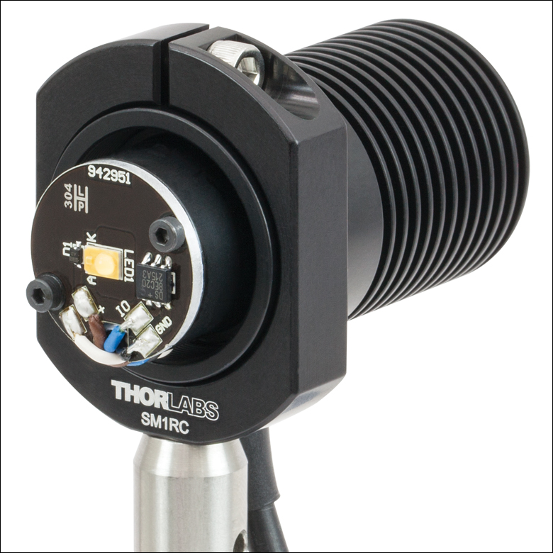
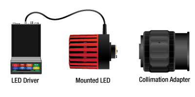
Figure 1.5 A mounted LED requires an LED driver to run; a collimation adapter (optional) collimates the diverging beam emitted by the LED. See Tables G1.1 through G9.1 to determine the appropriate LED driver. To determine the needed collimation adapter for a given LED, see the info icons (
Mounted LED Features
- Wavelengths Ranging from 233 nm to 5200 nm (See Table 1.2)
- White, Broadband, and Dual-Peak LEDs Also Available
- Integrated Memory Stores LED Operating Parameters
- Thermal Properties Optimized for Stable Output Power
- Microscope- and SM-Thread-Compatible Collimation Adapters Available
- 4-Pin Female Mating Connector for Custom Power Supplies can be Purchased Separately
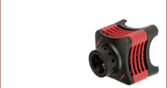
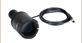
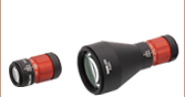
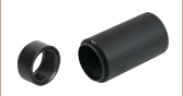
Each Thorlabs uncollimated, mounted LED consists of a single LED mounted to the end of a heat sink with 6 mm deep, SM1 (1.035"-40) internal threads. LEDs with Ø1.20" heat sinks have the same outer diameter as an SM1 Lens Tube, allowing them to fit inside a 30 mm Cage System. A selection of our LEDs are mounted to larger heat sinks, as they generate more heat during operation. These heat sinks are enclosed in Ø57.0 mm vented plastic housings and include four 4-40 tapped holes on the front for integration with 30 mm cage systems.
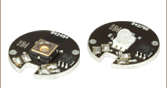
Every LED features an EEPROM chip which stores information about the LED (e.g., current limit, wavelength, forward voltage). When controlled by a Thorlabs LED driver designed to read the EEPROM chip, the data can be used to implement smart safety features.
These mounted LEDs possess good thermal stability properties, eliminating the issue of degradation of optical output power due to increased LED temperature. For more details, please see the Stability tab.
Please note that mounted LEDs are not intended for use in household illumination applications.
LED Collimation
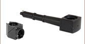
Our adjustable collimation adapters can translate a Ø1" (Ø25 mm) or Ø2" (Ø50 mm) lens by up to 11 mm or 20 mm, respectively. Each adjustable collimation adapter includes an internal SM2 (2.035"-40) thread adapter so that the LEDs can be easily integrated with Thorlabs' SM2-threaded components, such as our Ø2" lens tubes. These adapters are offered in versions with and without an AR-coated aspheric condenser lens.
In addition, microscope collimation adapters are available that incorporate an AR-coated aspheric lens. These adapters mate to the epi-illumination ports on select Leica DMI, Nikon Eclipse Ti, Olympus IX/BX, or Zeiss Axioskop microscopes. Thorlabs also offers mounted LEDs with pre-attached microscope collimation adapters.
We offer suggestions for collimating most LEDs. Click on the info icon (![]() ) for each LED below for details. The Collimation tab provides additional information on collimating an LED.
) for each LED below for details. The Collimation tab provides additional information on collimating an LED.
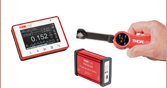
Driver Options
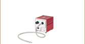
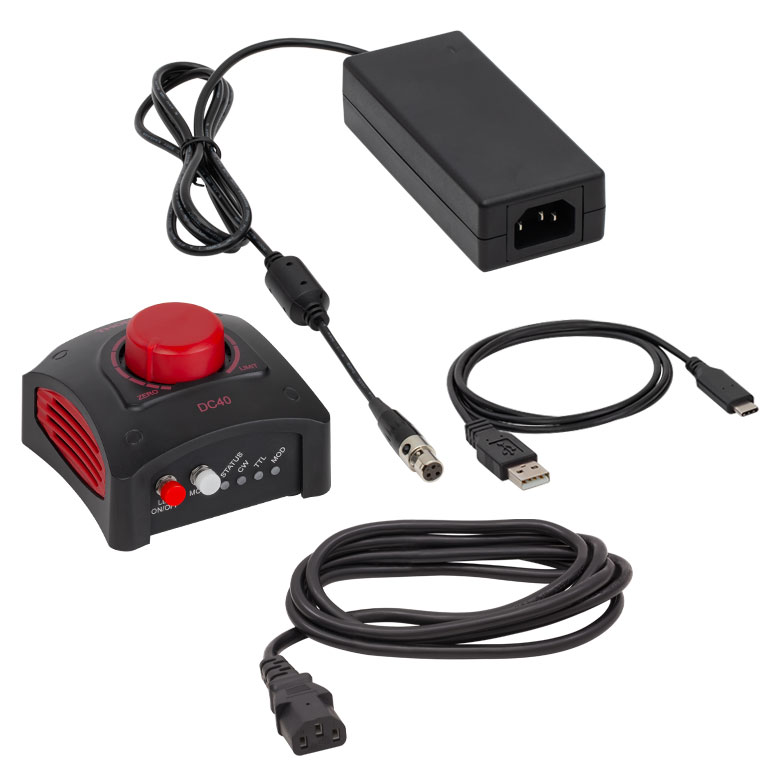
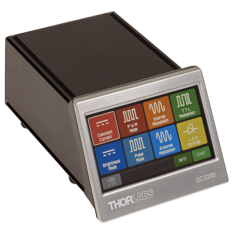
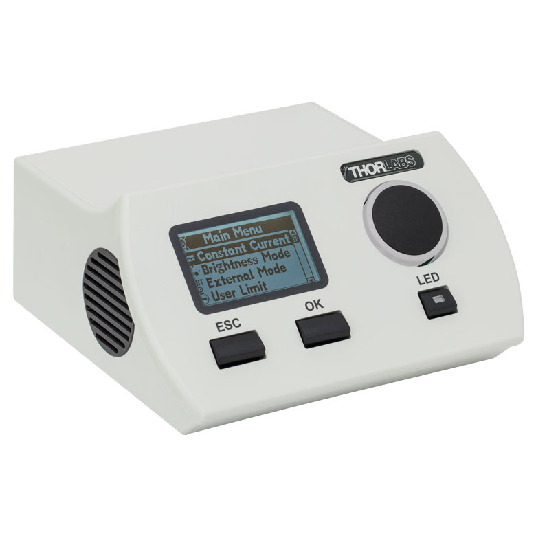
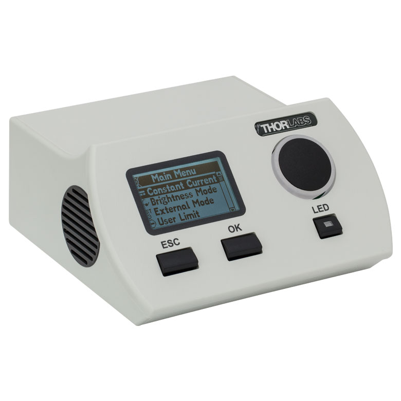
Thorlabs offers six drivers compatible with some or all of these LEDs: LEDD1B, UPLED, DC40, DC2200, DC4100, and DC4104 (the latter two require the DC4100-HUB). See Tables G1.1 through G9.1 for driver compatibility information, and the LED Drivers tab for a list of specifications. The UPLED, DC40, DC2200, DC4100, and DC4104 drivers are capable of reading the current limit from the EEPROM chip of the connected LED and automatically adjusting the maximum current setting to protect the LED.
Multi-LED Source
A customizable multi-LED source may be constructed using our mounted LEDs and other Thorlabs items. This source may be configured for integration with Thorlabs' versatile SM1 Lens Tube Systems and 30 mm Cage Systems. Please see the Multi-LED Source tab for a detailed item list and instructions.
Thorlabs also offers integrated, user-configurable 4-Wavelength High-Power LED Sources.
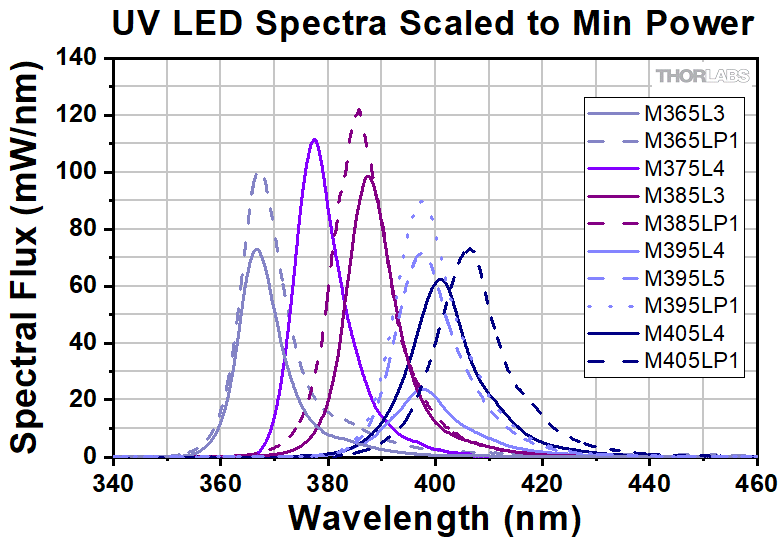
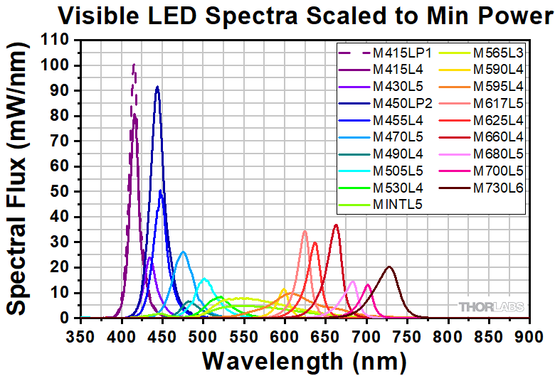
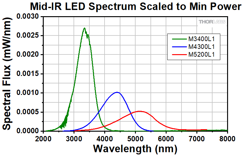
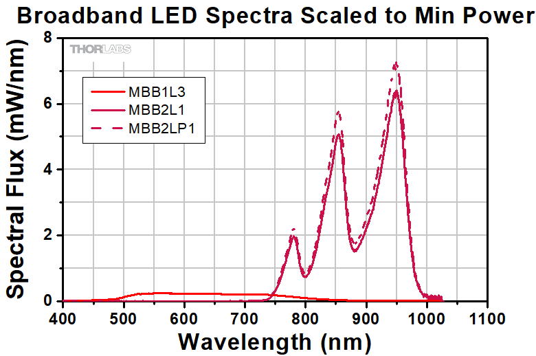
Relative Power
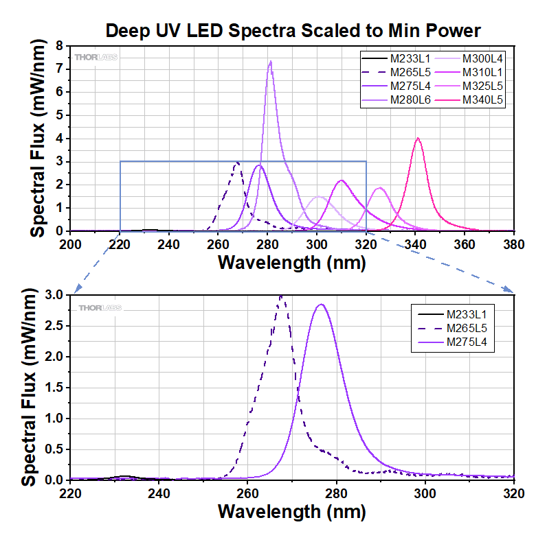
The actual spectral output and total output power of any given LED will vary due to variations in the manufacturing process and operating parameters, such as temperature and current. Both a typical and minimum output power are specified to help you select an LED that suits your needs. Each mounted LED will provide at least the minimum specified output power at the maximum current. In order to provide a point of comparison for the relative powers of LEDs with different nominal wavelengths, the spectra in the plots here have been scaled to the minimum output power for each LED. This data is representative, not absolute. Excel files with normalized and scaled spectra for each set of the mounted LEDs can be downloaded by clicking below the graphs.

Click to Enlarge
Click Here for Data
The spectrum shown for M4300L1 and M5200L1 are ideal.
Please see their Spec Sheets for more information.


Click to Enlarge
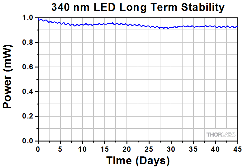
Figure 3.1 Our 340 nm mounted LED has a typical lifetime of >3,000 hours. In this case, the unit under test continued to provide more than 90% of its initial power after 45 days.
LED Lifetime and Long-Term Power Stability
One characteristic of LEDs is that they naturally exhibit power degradation with time. Often this power degradation is slow, but there are also instances where large, rapid drops in power, or even complete LED failure, occur. LED lifetimes are defined as the time it takes a specified percentage of a type of LED to fall below some power level. The parameters for the lifetime measurement can be written using the notation BXX/LYY, where XX is the percentage of that type of LED that will provide less than YY percent of the specified output power after the lifetime has elapsed. Thorlabs defines the lifetime of our LEDs as B50/L50, meaning that 50% of the LEDs with a given item # will fall below 50% of the initial optical power at the end of the specified lifetime. For example, if a batch of 100 LEDs is rated for 150 mW of output power, 50 of these LEDs can be expected to produce an output power of ≤75 mW after the specified LED lifetime has elapsed.
Click to Enlarge
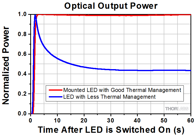
Figure 3.2 Optimized Thermal Management is Required for Stable Long-Term Optical Output Power
Figure 3.1 shows example data from long-term stability testing over a 45 day period for a 340 nm mounted LED, which had a lifetime of >3,000 hours (~125 days). The small power drop experienced by the LED after it is turned on is typical behavior during the first few minutes of operation. It corresponds to the period of time required for the LED to warm up to the point where it is thermally stable. Please note that this graph represents the performance of a single LED; the performance of individual LEDs will vary within the stated specifications.
Optimized Thermal Management
The thermal dissipation performance of these mounted LEDs has been optimized for stable power output. The heat sink is directly mounted to the LED mount so as to provide optimal thermal contact. By doing so, the degradation of optical output power that can be attributed to increased LED junction temperature is minimized (see Figure 3.2).
Video Insight: Collimate Light from an LED
Collimating light from an LED or other large, incoherent source can be a surprisingly challenging task. The emitter’s size and the collimating lens’ focal length and numerical aperture (NA) all influence the characteristics of the collimated beam. It can also be hard to know when the lens is positioned optimally. In this video, two collimation approaches are demonstrated. In addition, two lenses with different NAs and focal lengths are used to show that a benefit of increasing the lens’ NA is collecting more power from the LED, but that a higher NA comes at a cost of increasing the rate at which the collimated beam diverges.
Two Collimation Methods for LEDs
As demonstraded in Video 4.1, the distance between the selected collimating optic and the LED may need to be adjusted to ensure that the LED is suitably collimated. Collimation can only be achieved over a local region of the beam path. In this collimated region the beam has minimal divergence and will not converge at any point. As with any beam, perfect collimation is not achievable; any collimated beam diverges at some rate. For incoherent sources like LEDs, the rate of divergence is higher when the emitter size is larger. Two methods for achieving a collimated beam are outlined here.
Method 1: Form an Image of the LED at Infinity
- Power on the LED.
- Place a viewing screen ~1-2 feet away from the collimating optic.
- Adjust the distance between the collimating optic and the LED to form an image of the LED on the viewing screen (Figure 4.2).
- Move the viewing screen farther away from the LED.
- Repeat steps 3 and 4 as much as space allows.
- Returning the viewing screen to ~1-2 feet away from the collimating optic should show a non-converging, homogenous beam. The beam should be somewhat circular, may have a slightly polygonal shape, and should not be a clear image of the LED itself. Figure 4.4 shows an example of a collimated beam.
- Once the optimal position of the collimating optic has been found, lock the position of the collimating optic in place.
Note: Space contraints may limit this approach's usefulness. When space is limited, method 2 (below) may be more advantageous.
Click to Enlarge
Figure 4.2 Image of the LED
Click to Enlarge
Figure 4.3 Uncollimated Beam
Click to Enlarge
Figure 4.4 Collimated Beam
Method 2: Use the Divergence of the Beam to Set the Collimating Optic Position
- Determine the expected beam diameter (D2) a distance L away from the output of the collimating optic:
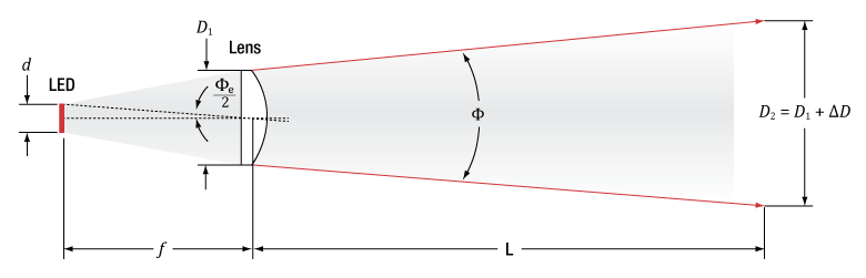
Click to Enlarge
Figure 4.5 Expected beam divergence after the collimating optic. Light emitted by an LED of size d is collected by a lens of diameter D1 and focal length f, which yields a divergence angle Φ after the lens. A distance L away from the lens the beam has expanded to size D2 = D1 + ΔD.
Figure 4.5 shows the propagation of the beam emitted by the LED and passing through the collimating optic. The expected divergence angle of the beam (Φe) after the collimating optic is given by


- Power on the LED.
- Place a viewing screen at distance L away, and adjust the position of the collimating optic to set D2 on the viewing screen.
- This is the optimal position of the collimating optic; lock the position of the collimating optic in place.
Table 4.6 provides examples of how the half viewing angle changes for select LEDs with the addition of a Ø1" aspheric condenser lens (ACL2520U). See the Collimation Adapter tab in the info icons ( ![]() ) below for the recommended collimating optic for select LEDs.
) below for the recommended collimating optic for select LEDs.
| Table 4.6 Collimated LED Performance | ||||||
|---|---|---|---|---|---|---|
| Item # | Color | Nominal Wavelengtha |
Calculated Lens to Emitter Distanceb | Half Viewing Anglec | ||
| +1 mm Out of Focusd | at Calculated Focusing Distance | -1 mm Out of Focusd | ||||
| M850L3 | IR | 850 nm | 13.8 mm | 3.29° | 3.10° | 3.93° |
| M940L3 | IR | 940 nm | 13.9 mm | 3.42° | 2.46° | 3.70° |

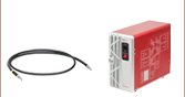
| Pin | Specification | Color |
|---|---|---|
| 1 | LED Anode | Brown |
| 2 | LED Cathode | White |
| 3 | EEPROM GND | Black |
| 4 | EEPROM IO | Blue |
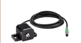
Pin Connection - Male
The pin diagram shows the male connector of the mounted LED assembly. It is a standard M8 x 1 sensor circular connector. Pins 1 and 2 are the connection to the LED. Pin 3 and 4 are used for the internal EEPROM in these LEDs. If using an LED driver that was not purchased from Thorlabs, be careful that the appropriate connections are made to Pin 1 and Pin 2 and that you do not attempt to drive the LED through the EEPROM pins.
Click to Enlarge
Figure 6.1 Multi-LED Source Coupled to Microscope Illumination Port
Creating a Custom Multi-LED Source for Microscope Illumination
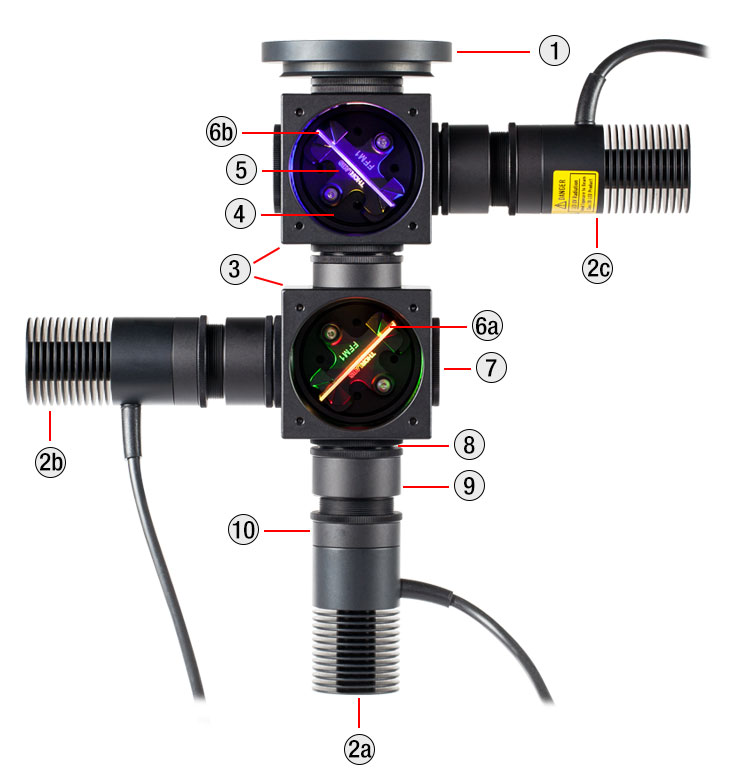
Thorlabs offers the items necessary to create your own custom multi-LED light source using two or three of the mounted LEDs offered below. As configured in the following example, the light source is intended to be used with the illumination port of a microscope. However, it may be integrated with other applications using Thorlabs' versatile SM1 Lens Tube and 30 mm Cage Systems. Thorlabs also offers integrated, user-configurable 4-Wavelength LED Sources.
Design & Construction
First, light will be collimated by lenses mounted in lens tubes. Dichroic mirrors mounted in kinematic cage cubes then combine the output from the multiple LEDs. The mounted LEDs may be driven by LEDD1B Compact T-Cube LED Drivers (power supplies are sold separately). The LEDD1B LED Drivers allow each LED's output to be independently modulated and can provide up to 1200 mA of current. Please take care not to drive the LED sources above their max current ratings.
When designing your custom source, select mounted LEDs from below along with dichroic mirror(s) that have cutoff wavelength(s) between the LED wavelengths. The appropriate dichroic mirror(s) will reflect light from side-mounted LEDs and transmit light along the optical axis. Please note that most of these dichroic mirrors are "longpass" filters, meaning they transmit the longer wavelengths and reflect the shorter wavelengths. To superimpose light from three or more LEDs, add each in series (as shown in Figure 6.2), starting from the back with longer wavelength LEDs when using longpass filters. Shortpass filters may also used if the longer wavelength is reflected and the shorter wavelength is transmitted. Sample combinations of compatible dichroic mirrors and LEDs are offered in Tables 6.4, 6.5, and 6.6.
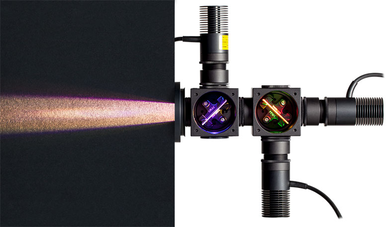
It is also necessary to select an aspheric condenser lens for each source with AR coatings appropriate for the source. Before assembling the light source, collimate the light from each mounted LED as detailed in the Collimation tab. For mounting the aspheric lenses in the SM1V05 Lens Tubes using the included SM1RR retaining rings, we recommend the SPW801 Adjustable Spanner Wrench. A properly collimated LED source should have a resultant beam that is approximately homogenous and not highly divergent at a distance of approximately 2 feet (60 cm). An example of a well-collimated beam is shown on the Collimation tab.
After each LED source is collimated, thread the SM1V05 Lens Tubes at the end of each collimated LED assembly into their respective C4W Cage Cube ports using SM1T2 Lens Tube Couplers. Install each dichroic filter in an FFM1 Dichroic Filter Holder, and mount each filter holder onto a B4C Kinematic Cage Cube Platform. Each platform is then installed in the C4W Cage Cubes by partially threading the included screws into the bottom of the cube, and then inserting and rotating the B4C platform into place. Align the platform to the desired position and then firmly tighten the screws. To connect multiple cage cubes and the microscope adapter, use the remaining SM1T2 lens tube couplers along with an SM1L05 0.5" Lens Tube between adjacent cage cubes. Finally, adjust the rotation, tip, and tilt of each B4C platform to align the reflected and transmitted beams so they overlap as closely as possible.
If desired, a multi-LED source may be constructed that employs more than three LEDs. The limiting factors for the number of LEDs that can be practically used are the collimation of the light and the dichroic mirror efficiency over the specified range. Heavier multi-LED sources may be supported with our Ø1" or Ø1.5" Posts.
Click to Enlarge
Figure 6.2 Three-LED Source Using Components Mounted LEDs and Dichroic Mirrors
Detailed in Example Configuration 1
| Table 6.3 Parts List | |||||
|---|---|---|---|---|---|
| # | Product Description | Item # | 2 LEDs | 3 LEDs | |
| Item Qty. | |||||
| 1 | Microscope Illumination Port Adapter: |
Olympus IX or BX | SM1A14 | 1 | 1 |
| Leica DMI | SM1A21 | ||||
| Zeiss Axioskop | SM1A23a | ||||
| Nikon Eclipse Ti | SM1A26 | ||||
| 2 | Mounted LEDb | - | 2 | 3 | |
| - | T-Cube LED Driver, 1200 mA Max Drive Current | LEDD1Bc | 2 | 3 | |
| - | 15 V Power Supply for K- and T-Cube | KPS201c | 2 | 3 | |
| 3 | 4-Way Mounting 30 mm Cage Cube | C4W | 1 | 2 | |
| 4 | Kinematic Cage Cube Platform for C4W/C6W | B4C | 1 | 2 | |
| 5 | 30 mm Cage-Compatible Dichroic Filter Mount | FFM1 | 1 | 2 | |
| 6 | Dichroic Filter(s)d | - | 1 | 2 | |
| 7 | Externally SM1-Threaded End Cap | SM1CP2 | 1 | 2 | |
| 8 | SM1 (1.035"-40) Coupler, External Threads, 0.5" Long | SM1T2 | 3 | 5 | |
| 9 | Ø1" SM1 Lens Tube, 1/2" Long External Threads | SM1V05 | 2 | 3 | |
| - | Aspheric Condenser Lens |
AR-Coated 350 - 700 nm | ACL2520U-Ac,e | 2 | 3 |
| AR-Coated 650 - 1050 nm | ACL2520U-Bc,e | ||||
| 10 | SM1 Lens Tube, 0.3" Thread Depth | SM1L03 | 2 | 4 | |
| - | Blank Cover Plate with Rubber O-Ring for C4W/C6W | B1Cc | 1 | 2 | |
Click to Enlarge
Figure 6.7 Beam Profile of Source with 3 Mounted LEDs
Click to Enlarge
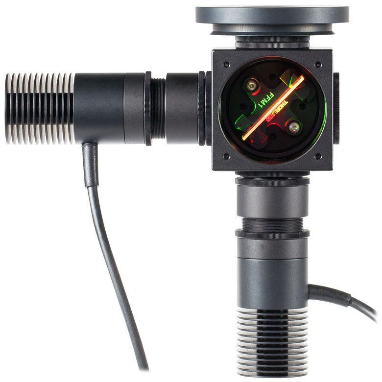
Figure 6.8 Two-LED source. This is the same as Example 1, but with the blue LED removed.
| Table 7.1 Ray Data for Zemax | ||||
|---|---|---|---|---|
| Item # | Information File | Available Ray Files | File Size | Click to Download |
| M850L3a | SFH4715S_100413_info.pdf | 100,000 Rays, 500,000 Rays, and 5 Million Rays | 140 MB | |
| M940L3a | SFH_4725S_110413_info.pdf | 100,000 Rays, 500,000 Rays, and 5 Million Rays | 140 MB | |
Ray data for Zemax is available for some of the bare LEDs incorporated into these high-powered light sources. This data is provided in a zipped folder that can be downloaded by clicking on the red document icons () next to the part numbers in the pricing tables below. Every zipped folder contains an information file and one or more ray files for use with Zemax:
- Information File: This document contains a summary of the types of data files included in the zipped folder and some basic information about their use. It includes a table listing each document type and the corresponding filenames.
- Ray Files: These are binary files containing ray data for use with Zemax.
For the LEDs marked with an superscript "a" in Table 7.1, the following additional pieces of information are also included in the zipped folder:
- Radiometric Color Spectrum: This .spc file is also intended for use with Zemax.
- CAD Files: A file indicating the geometry of the bare LED. For the dimensions of the high-power mounted LEDs that include the package, please see the support drawings provided by Thorlabs.
- Sample Zemax File: A sample file containing the recommended settings and placement of the ray files and bare LED CAD model when used with Zemax.
Table 7.1 summarizes the ray files available for each LED and any other supporting documentation provided.
| Components for Cerna® Compatibility |
|---|
| Epi-Illumination |
| WFA2001 Epi-Illuminator Module |
| Trans-Illumination |
| Illumination Kits |
Using Mounted LEDs in Cerna® Microscope Systems
Mounted LEDs, which can have either narrowband or broadband spectra, are useful for a range of applications within Thorlabs' Cerna microscopy platform:
- Fluorescence Microscopy
- Brightfield Microscopy
- Near Infrared/Infrared (NIR/IR) Microscopy
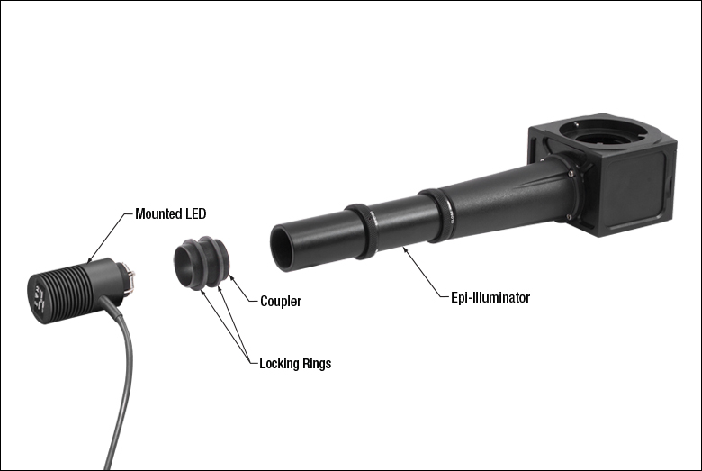
If you are interested in using a mounted LED with a Cerna modular microscopy system, the mounted LED can be attached by way of the single-cube epi-illuminator module (Item # WFA2001), which contains AR-coated optics optimized for the 350 - 700 nm wavelength range. The mounted LED and epi-illuminator module are connected together by an externally threaded coupler (Item # SM1T10, provided with the WFA2001), which includes two knurled locking rings (Item # SM1NT, also provided with the WFA2001) that are tightened by hand. The mounted LED is then powered by a driver, sold separately. Please see the LED Drivers tab to identify the appropriate driver for your mounted LED. If you wish to connect multiple mounted LEDs to the epi-illuminator module, contact Technical Support.
 Click to Enlarge
Figure 8.1 An exploded view of the mounted LED and its connection with the WFA2001 epi-illuminator module.
 Click to Enlarge
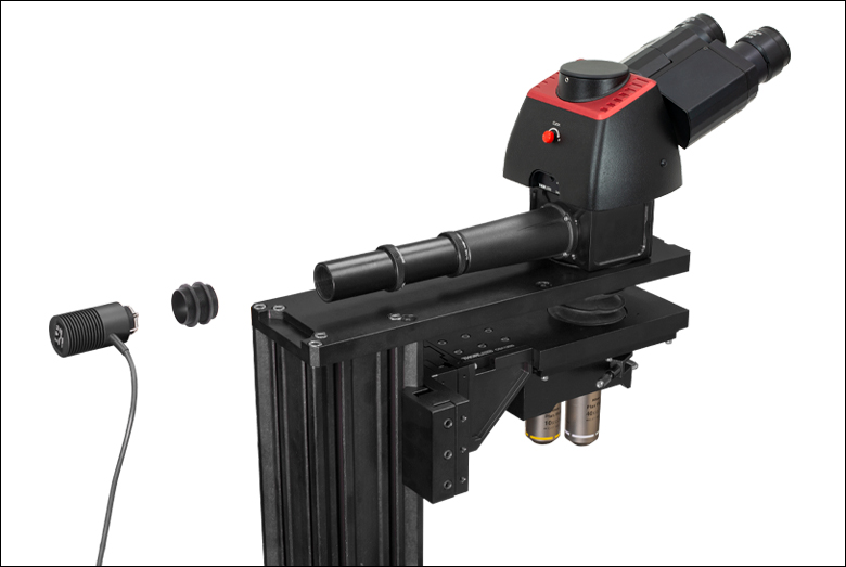
Figure 8.2 Attaching the mounted LED is possible before or after connecting the epi-illuminator module to the microscope.
 Click to Enlarge
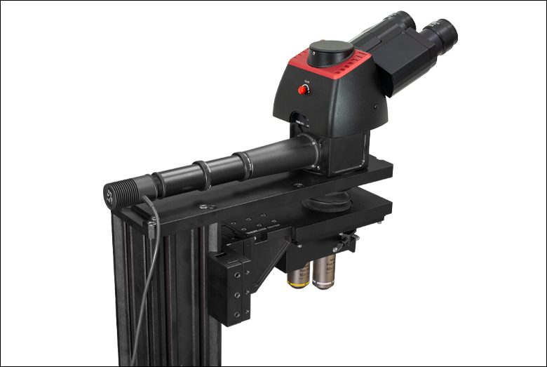
Figure 8.3 The mounted LED and epi-illuminator module attached to the Cerna microscope.
Please see the Overview tab to choose the appropriate color spectrum of mounted LED for your imaging needs. Again, note that the epi-illuminator module is optimized for 350 - 700 nm wavelength illumination sources.
Certain mounted LEDs are also compatible with our illumination kits for trans-illumination. Please contact Technical Support if you wish to use an LED not currently offered as a component of these kits, as the collimating optics are optimized for certain beam characteristics.
To fully support the max optical power of the LED you intend to drive, ensure that the max voltage and max current of the driver are equal to or greater than those of the LED. Drivers matching these conditions are listed in the Recommended Drivers columns of Tables G1.1 through G9.1.
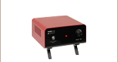
| Compatible Drivers | LEDD1B | UPLEDa | DC40a | DC2200a | DC4100a,b | DC4104a,b |
|---|---|---|---|---|---|---|
| Click Photos to Enlarge | 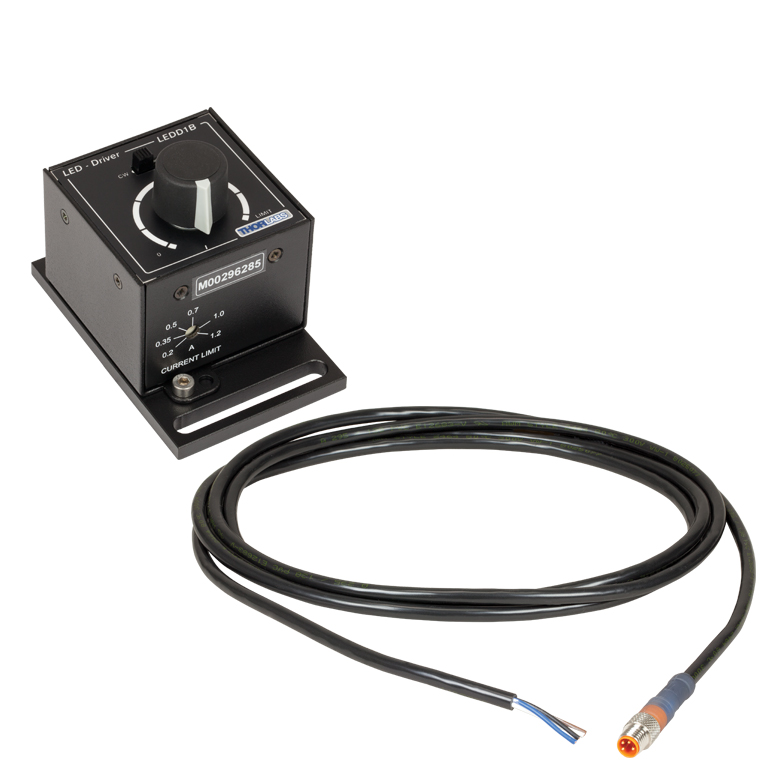 |
 |
 |
 |
 |
 |
| LED Driver Current Output (Max)c | 1.2 A | 1.2 A | 4.0 Ad | LED1 Terminal: 10.0 A LED2 Terminal: 2.0 Ae |
1.0 A per Channel | 1.0 A per Channel |
| LED Driver Forward Voltage (Max)f | 12 V | 8 V | 14.0 Vd | 50 V | 5 V | 5 V |
| Modulation Frequency Using External Input (Max) | 5 kHzg | - | 5 kHzg | 250 kHzg,h | 100 kHzg (Simultaneous Across all Channels) |
100 kHzg (Independently Controlled Channels) |
| External Control Interface(s) | Analog (BNC) | USB 2.0 | USB 2.0, TTL, and Analog (BNC) | USB 2.0 and Analog (BNC) | USB 2.0 and Analog (BNC) | USB 2.0 and Analog (8-Pin) |
| Main Driver Features | Very Compact Footprint 60 mm x 73 mm x 104 mm (W x H x D) |
USB-Controlled | Driver Current Up to 4.0 A, Manual and USB-Controlled |
Touchscreen Interface with Internal and External Options for Pulsed and Modulated LED Operation | 4 Channelsb | 4 Channelsb |
| EEPROM Compatible: Reads Out LED Data for LED Settings | - | |||||
| LCD Display | - | - | - |
| Posted Comments: | |
Víctor Rico
(posted 2025-07-24 19:16:47.763) Hi Thorlabs team!
At Conceivable, we are wondering why—if there is no UV emission in your LED530L4, as can be seen from the spectral information—a warning legend appears stating: “UV light emitted from this product.”
For me and my team, this is not a problem; we look at the spectrum and feel confident when working with live cells. But clinicians read this warning and become alarmed—to the point that they don’t want to use this light at all.
Is there any argument beyond the spectral information that justifies including this legend? jjadvani
(posted 2025-07-25 07:49:52.0) Dear Victor, Thank you for pointing this out. I'll contact you directly to provide clarification and additional information about this. user
(posted 2025-07-07 15:05:58.02) Hello, could you clarify if there are any limitations regarding the orientation of the LEDs when used in a room with a well-controlled ambient temperature?
Can they be used vertically, pointing up or down, or at an angle? jjadvani
(posted 2025-07-08 02:01:37.0) Dear user, thank you for your request. You can mount this LED in vertical, Horizontal or any other orientation of your choice depending upon your application. There is no limitation regarding orientation when operated with in specification Miklos Kedves
(posted 2025-06-13 18:02:14.767) Dear Thorlabs,
We are looking for a white LED light source that is vacuum compatible, to illuminate a target surface in a vacuum chamber. Can you offer such a product?
Best regards, Miklos Kedves jjadvani
(posted 2025-06-16 06:15:52.0) Dear Miklos, Thank you for your feedback. Unfortunately, our LEDs are not rated for use in vacuum environments. I will contact you directly to provide you further support. David Rost
(posted 2025-06-10 06:04:12.34) Hello,
what is the meaning of L2 or L3 ... L5 at the end?
Regards, David hchow
(posted 2025-06-10 10:32:06.0) Dear Mr. Rost, thank you for your feedback. The L(X) numbers at the end of the product name is simply the version number of the particular mounted LED. Dogan Sinar
(posted 2025-05-22 13:29:51.81) Hi,
I would like to learn about the expected rise/fall times for this LED.
Thank you hkarpenko
(posted 2025-05-23 08:53:04.0) Dear Dogan,
thank you for your request. The rise and falltime of LEDs is usually in the µs or ns regime and is dependend on the LED type and material. I will contact you directly to discuss your application in detail with you. min soo kang
(posted 2025-01-10 18:06:50.77) Can the MCWHL7 product be combined with SM1 Lens Tubes? The internal threads are not indicated in the product labeling or SolidWorks model, but they are mentioned in the product description. Could you please clarify this? tschmidt
(posted 2025-01-10 08:32:36.0) Dear Min Soo Kang,
thank you for your feedback. Yes, the MCWHL7 and our other mounted LEDs of this type have an internal SM1 threading. In the Auto CAD PDF file you find the respective technical drawing and see the SM1 internal threading at the LED’s housing. You can connect a lens tube with the external SM1 threading side to it (e.g. SM1L10). We also provide lens tubes with external threads on both sides (e.g. SM1S10), if you require it for your application. Víctor Rico
(posted 2024-11-08 13:07:35.613) Dear Thorlabs team,
I’d like to bring something to your attention. I noticed a slight discrepancy between the spectral data provided for the LED530L4 LED diode (file: M530L4_data.xlsx) and the corresponding graph displayed on the website. While the spectrum shape is consistent with the reported data, the data in the file appears in a stepwise, “staircase” format, whereas the online graph shows a smoother, continuous curve. hchow
(posted 2024-11-11 03:27:26.0) Dear Mr. Rico, thank you for your feedback. As far as I can see, there are no mistakes in our Excel data for the spectral shape of the M530L4's LED.I believe this is a question on the formatting of the graph on your Excel program you are using to open the .xlsx data. Also the fact that in the spectral diagram, the main data points around 525 nm are exaggerated. Liping Sun
(posted 2024-08-25 08:37:51.487) We regulate the outgoing light power of M310L1 and M340L5 by adjusting the DC current of LEDDIB controller in the experiment. However, when the maximum forward current of LEDDIB to M310L1 and M340L5 is adjusted, The measured optical power can not reach the minimum output power of M310L1 and M340L5. What might be the cause? jjadvani
(posted 2024-09-02 05:40:01.0) Dear Ling, Thank you for providing feedback. Reduced power output can occur for a variety of causes. I will contact you directly to troubleshoot this. Shaodi ZHU
(posted 2024-08-22 15:02:48.837) We would like to design our illumiation system using M265L5 and M280L6. Could you please provide the data file for simulation of these led light source? (e.g. .dat for zemax)
Instead, if possible, could you provide the LED chip model that has been mounted upon? jjadvani
(posted 2024-08-22 06:04:59.0) Dear Shaodi, thank you for contacting Thorlabs. I will contact you personally to provide you information you need. gong liu
(posted 2024-04-10 03:18:50.49) Could you please share the light-emitting area of the LED in M730L5? jjadvani
(posted 2024-04-10 07:49:08.0) Dear gong, Thank you for your inquiry. Emmiter size of this LED is 1 mm x 1 mm. You can check this in spec sheet of LED. Haojie Zhang
(posted 2024-04-02 22:06:25.553) How can i use the EEPROM pin of MBWHL4 without your specific LED drivers? dpossin
(posted 2024-04-02 11:39:28.0) Dear Haojie,
Thank you for your feedback. I reach out to you in order to provide further information. Yuhao Yuan
(posted 2024-01-18 16:35:05.54) Hi there, I would like to maximize the output power of M1300L4 after collimation with SM2F and ACL50832U. But the output average power is about 30 mW which is far less than 180 mW. Do you have any suggestions to increase the power? dpossin
(posted 2024-01-19 07:25:48.0) Dear Yuhao,
Thank you for your feedback. I reach out to you directly to discuss your application. AMUL RAMSOGE
(posted 2023-09-23 17:16:47.67) Can you please share any documents elaborating how to hold M280L6 mechanically and standard accessories available with Thor labs for holding. hchow
(posted 2023-09-26 05:59:21.0) Dear Mr. Ramsoge, thank you for your enquiry. I will personally reach out to you to provide more information. Thank you. Warren Massey
(posted 2023-09-06 13:17:47.347) The datasheet says to power this LED with no more than 1000mA, yet all the optical ratings for the LED are when it is powered with 1000mA suggesting a lower/safer current not be used during operation (i.e., no current safety margin). That leads me to believe that 1000mA is actually a NOMINAL maximum current and that there is some tolerable variation allowed around that value. What is the acceptable range of maximum operating current? FWIW, looking at your suggested companion "upLED driver", it says: "LED Current Accuracy: ±(1% + 10 mA)" which would suggest that 1110mA is an acceptable upper current limit given that this suggested driver might supply just that. Looking at your suggested companion "basic LED driver", its current limit is a manually-adjusted potentiometer, whose setting depends upon on some adjacent ballpark silkscreen labels so I doubt it's much better at establishing a ±10% current limit. hchow
(posted 2023-09-11 05:33:30.0) Dear Mr. Massey, thank you for your feedback. We suggest our customer to not exceed the maximum driving current of the LED, as adverse effects to the LED can occur. If too much current is used, the LED will start to overheat, causing a colour shift, or burn out, and at the worst case, fragmentation of the LED. The upLED LED driver is able to read the EEPROM chip on board the mounted LED and is able to automatically adjust the current. Moreover, there is a current limit switch on the manual LED driver, LEDD1B, which limits the maximum driving current. In either cases, the maximum current is not exceeded. Pedro Mecê
(posted 2023-07-25 14:05:38.44) Hello, I am interested on the M810L3 because its high irradiance and near-infrared wavelength. If I understand well this product is obsolete. What are the similar alternatives that you can propose?
Thanks hchow
(posted 2023-07-26 03:23:39.0) Dear Mr. Mece,
thank you for your feedback. Actually, the M810L3 is still available for purchase from us. I just checked, we still have stock of this item. In any case, I will contact you to provide more information. Thank you. Jackson Knappen
(posted 2023-04-26 07:46:00.55) We measured two separate MNWHL4 4900K LEDs using a calibrated JETI spectroradiometer. Our measurements showed a spectrum that was significantly different from the Thorlabs spec with significantly more blue energy and a CCT closer to 6500K or even greater. hchow
(posted 2023-04-27 04:06:02.0) Dear Mr. Knappen, thank you for your feedback. I will personally reach out to you to find solutions to the problem you are facing. Thank you. Jay Han
(posted 2023-02-13 12:53:31.247) Hello, I am using LED 940nm with DC2200 driver and I have the following questions in TTL modulation mode.
1.I would like to know the time/delay response vs. the LED current setting.
2.I want to know the rising/falling time of output according to the LED current.
Thanks,
Jay hkarpenko
(posted 2023-02-15 10:32:32.0) Dear customer,
thank you for your feedback. We have a documentation about that. I will send you our test protocol regarding the rise and fall time measurements of the DC2200 LED driver. Kevin M
(posted 2023-01-31 15:12:23.323) Hello,
The LED works as specified. Is it vacuum compatible?
We would be operating at around 10^(-5)mb
Thanks,
Kevin hchow
(posted 2023-02-01 06:06:55.0) Dear Kevin, thank you for your feedback. Unfortunately, the M1050L2 isn't rated to be used in a vacuum environment. Thermal paste and solder is used in the internal LED's PCB and additionally the housing is anodized, all of which can begin to outgas in a vacuum. shlomi tapiro
(posted 2022-12-27 16:52:42.983) HI
I need for my work the item M810L3 because I need to use a wavelength of 810nm, plus the whole assembly of this particular item fits me in the array.
I see with you that it is obsolete, what is the item that replaces this item?
I can't find anything exactly like it, and I have to buy this product
In addition
I have other arrays that I have already purchased and I am required to maintain them.
What to do? dpossin
(posted 2022-12-28 06:34:33.0) Dear Shlomi,
Thank you for your feedback. Unfortunately currently we do not offer mounted LEDs emitting at 810nm. I reach out to you in order to discuss alternatives. Kath Wood
(posted 2022-11-16 16:53:58.4) Hi - does the spectrum plot in the Spec Sheet have the correct x-axis labels? It looks off. The peak looks more like 480 nm - that's fine, I just wanted to check...
Thanks for your help!
Katherine hchow
(posted 2022-11-21 03:11:52.0) Dear Katherine,
thank you for your valuable feedback. I will personally reach out to you to provide more information about the M490L4 in question.
Thank you. Chuanpu Liu
(posted 2022-09-28 16:29:45.673) For the M405L4 - 405 nm, is there a power supply available in Thorlabs? Thanks! dpossin
(posted 2022-09-30 03:14:50.0) Dear Chuanpu,
Thank you for your feedback. We offer several options in order to drive our mounted LEDs like the M405L4. You could either use our most basic LED controller namely the LEDD1B or use a more advanced controller. Please see our selection here: https://www.thorlabs.de/navigation.cfm?guide_ID=2109. I reach out to you in order to provide further assistance. Jonas Kublitski
(posted 2021-12-08 15:18:07.843) Hi,
the LED works as expected. However, this is a mounted LED, which means people will keep threading it in and out all the time. It is super annoying to do so with the cable.
My suggestion:
It would be perfect if one could disconnect the cable from the LED, such that while mounting one wouldn't have to mind the cable.
Moreover, having the cable like this, makes you break it quite easily, as you keep twisting it..
I believe this applies to all mounted LED..
Thanks
Jonas wskopalik
(posted 2021-12-13 03:22:35.0) Dear Jonas,
Thank you very much for your feedback and your suggestion!
I will forward your idea to our engineering team so they can consider it for future design improvements. I will also reach out to you directly. Wijnand Twivey
(posted 2021-11-21 13:31:31.543) Dear SIr,
Wat ik can not find is the type of cable, wire size and the lenght of the attached cable.
Can you send me this informatie,
With kind regards,
Wijnand twivey
Electrical Hardware Engineer / Eplan Engineer.
Kremer industriele Automatiserings bv. soswald
(posted 2021-11-25 03:10:53.0) Dear Wijnand,
thank you for your feedback. I have reached out to you directly to provide the required information and discuss your application in more detail. Nicolas Villa
(posted 2021-11-20 07:32:34.987) Hello,
I have a mounted LED M505L3. Is the DIY SM1-Threaded collimation assembly compatible with the M505L3 ?
Best regards,
Nicolas dpossin
(posted 2021-11-24 10:14:13.0) Dear Nicolas,
Thank you for your inquiry. The M503L3 can be mounted to any DIY SM1 threaded collimation adapter. However the easiest optoin is to use our collimation adapter SM1U25-A: https://www.thorlabs.de/thorproduct.cfm?partnumber=SM1U25-A Chen Chuan Teo
(posted 2021-08-26 15:56:18.29) Hi Mates,
I have bought this LED and i wish to download the certificate of RoHS, but seem like cannot download from website. Can you please email me the certificate of this item? MKiess
(posted 2021-08-30 11:09:23.0) Dear Chen Chuan Teo, Thank you for your inquiry. Sorry that the download is not working at the moment, we will fix this issue as soon as possible. I have contacted you directly to send you the certificate. Tianxiang Ling
(posted 2021-07-14 17:25:51.17) Maximum Irradiance was 13.5 µW/mm2
Measured at a Distance of 200 nm?
I want to know the distance is 200 nm or 200 mm?? soswald
(posted 2021-07-15 08:54:20.0) Dear Tianxiang Ling,
thank you for your feedback. The sensor that was used to measure the typical irradiance of the MBB2LP1 was placed at a distance of 200 mm from the LED. Torsten Rehwald
(posted 2021-07-06 03:45:40.533) Dear Sir or Madam,
could you please provide me information about the correct protective glasses during the use of the LED M450LP1.
Thanks a lot for your support.
Kind regards
Torsten Rehwald MKiess
(posted 2021-07-07 11:25:54.0) Dear Torsten, thank you very much for your inquiry. I contacted you directly to discuss the specific requirements. Jiun-Yann Yu
(posted 2021-05-14 19:09:13.06) Hi,
I was wondering what the maximum output (optical) power is for this LED. Does it go beyond 1 Watt? The spec on your website doesn't seem to provide any reference or estimation for this.
Thanks. MKiess
(posted 2021-05-18 07:24:58.0) Dear Jiun-Yann, thank you very much for your inquiry. The specified optical power of, typically 542mW, for the M810L4, you will get when driving the LED with the maximum current of 1000mA. Therefore, you will not achieve 1W power with this LED. I have contacted you directly to discuss further possibilities. Lili Tang
(posted 2020-11-09 14:16:30.477) I require the wavelength range of the LED source,but products were discontinuded,so i cannot find it ,please send it to me ,thanks. dpossin
(posted 2020-11-10 05:37:50.0) Dear Lili,
Thank you for your feedback. Even though the products has been discontinued, the spec sheets can be still found under "drawing and documents" here: https://www.thorlabs.com/thorproduct.cfm?partnumber=MCWHL5&pn=MCWHL5. I am sending you the specsheet anyway. Julian Kleber
(posted 2020-09-21 03:05:01.9) Hi,
I tried to download the datasheet of the M940L3 for several days now. It seems as if this link isn't working anymore. Could you fix this so that I can download it?
https://www.thorlabs.com/_sd.cfm?fileName=25177-S01.pdf&partNumber=M940L3
Is there any information on the EEPROM that is unique for a specific mounted LED ? (E.g. serial, timestamp,....)
Can I read this information without using your LED drivers?
Best
Julian MKiess
(posted 2020-09-22 04:14:25.0) Dear Julian, thank you very much for contacting Thorlabs. I have sent you the specification sheet directly.
The EEPROM chip stores information regarding current, voltage, wavelength etc. This information can be accessed via our Thorlabs controllers. This includes information such as type and serial number of the LED itself. Niall Martin
(posted 2020-07-01 07:52:59.99) I think the pin number on the data sheet for this product are incorrect according to the standard for M8 connectors
It seems pin 3 and pin 4 are labelled the wrong way round, but pins 1 and 2, and the wire colours are correct
Please could you check and confirm.
I am basing this on the fact that all other manufacturers I can find for m8 cables asundararaj
(posted 2020-07-07 10:11:40.0) Thank you for contacting Thorlabs. The labeling on the pin diagram of the CON8ML-4 is correct as per the drawing on the website. malcolm northcott
(posted 2020-04-22 19:54:42.987) Is it possible to get an excel spreadsheet with he measured special output for this LED MKiess
(posted 2020-04-24 05:31:55.0) This is an response from Michael of Thorlabs. Thank you very much for your inquiry. An Excel file with the spectral data can be downloaded from our website, by calling up the information of the desired LEDs in the info column. STATICE MP
(posted 2020-04-03 13:08:57.1) Good morning,
Do you have an other reference to propose ?
Waiting for your feedback aqap
Than you very much
M PIELLARD MKiess
(posted 2020-04-06 04:12:02.0) This is a response from Michael at Thorlabs. Thank you very much for your inquiry. An alternative to the M505L3, Mounted LED, is the newer version of this LED. This LED has the item number M505L4. Simon Meaney
(posted 2020-03-05 18:19:25.8) The technical drawings on the MCWHLP1 and MWWHLP1 Spec Sheets are incorrect.
They list the diameter as " 57.0mm (1.20") "
57mm is 2.24" which matches the AutoCad PDF for the products. MKiess
(posted 2020-03-06 06:54:05.0) This is a response from Michael at Thorlabs. Thank you very much for your inquiry. Thank you very much for this information. That is correct. We will correct it immediately. Pawel Hermanowicz
(posted 2020-01-12 07:10:11.1) Hi,
I would like to ask whether the ray sets for the M455L4 and M660L4 mounted LEDs are available, in ASCII (preferably) or Zemax format? wskopalik
(posted 2020-01-13 10:20:33.0) This is a response from Wolfgang at Thorlabs. Thank you very much for your inquiry!
I will contact you directly regarding these files. Bernd Polder
(posted 2019-11-29 08:01:58.357) In the website you also show a M595L4 with very good output power. I am interested in this product, but I only find the M595L3 in the ordering section. How is it possible to order thise M595L4 version?
Thank you
Best regards
Bernd Polder lmorgus
(posted 2019-12-02 11:14:24.0) A response from Laurie at Thorlabs to Bernd: I will reach out to you via email concerning your inquiry to purchase our next generation 595 nm LED, for which we had accidentally posted some information ahead of the formal release. Dongbin Lim
(posted 2019-09-30 17:00:34.623) Hello,
We would like to inquire about your product M470L3 certification.
We are using your product and we need your product certificate to be certified for the product we are developing.
I am writing to ask you this question because I cannot see Rohs certificate on your homepage.
I would appreciate it if you could send me my email with the certificate for M470L3.
Thank you. MKiess
(posted 2019-10-07 09:01:11.0) This is a response from Michael at Thorlabs. Thank you very much for your inquiry! In general you can find the RoHs certificates on our website for the respective articles. If you click on the red icon in the column 'Documents' on the product page where the article number is listed, you can download the certificates.
Since the M470L3 has been replaced by the newer M470L4, you can find the certificate under the following link:https: //www.thorlabs.com/thorproduct.cfm?partnumber=M470L3&pn=M470L3#4478 Evyatar kassוs
(posted 2019-08-07 12:13:37.653) I am using the M265L3 with dc2200 driver but can not get short pulses, what are the rise and fall times of M265L3 ? dpossin
(posted 2019-08-09 07:40:09.0) Hello Rafael,
Thank you for your request. It should be possible to create pulses of µs length with your setup. I am reaching out to you in order to give you further support. gjorgensen
(posted 2019-03-11 13:37:52.857) Hello-
I need to time a camera trigger after turning on your LED, but I could not find and spec for LED rise time in yoru documentation on the web site. Could you please let me know how long a delay I need to place in my code between the time I turn on the LED and triggering to camera so I am insured the LED has obtained at least 90% brightness? Thank you for your assistance. nreusch
(posted 2019-03-19 08:03:40.0) This is a response from Nicola at Thorlabs. Thank you very much for your inquiry! We do not specify rise and fall times of LEDs, but typical values are in the ns range. The rise and fall times of LED systems are, however, limited by the driver electronics in most cases. Using one of our LED drivers leads to response times in the several µs range. bhebert
(posted 2018-12-20 10:17:05.867) Do you offer a variety of this the uses the ushio EDC940DS-1100-S5 or can a special version be made? wskopalik
(posted 2018-12-28 05:36:06.0) This is a response from Wolfgang at Thorlabs. Thank you very much for your inquiry!
Unfortunately, we don't offer a mounted LED which uses this particular LED chip. I have however looked at the data sheet of this LED chip and the M940L3 seems to be quite similar in performance.
I will contact you directly to discuss your requirements in detail. yu-pu.lin
(posted 2018-12-19 10:29:50.383) What is the approximative spot size of the collimated beam at 20-50 mm distance using the SM2F32 Adjustable Collimation Adapter? (LED = M940L3)
Thank you! YLohia
(posted 2019-01-04 04:00:51.0) This is a response from Michael at Thorlabs. Thank you very much for your inquiry! I will perform a Zemax simulation with the M940L3 in combination with the adjustable collimator to determine the divergence angle and thus the resulting beam diameter at a distance of 20-50mm. I will send you the results directly. fcouweleers
(posted 2018-12-17 10:55:02.65) can you share which LED (probably OSRAM) is present in this assembly nreusch
(posted 2018-12-21 02:34:32.0) This is a response from Nicola at Thorlabs. Thank you for your inquiry! Unfortunately, we do not share the LED chip details of our mounted LEDs in general. Please contact your local Tech Support Team if you need specific information about the characteristics of the chip. joe.bron
(posted 2018-11-21 10:48:45.81) Will a diffuse condenser lens have much effect on its collimation compared to a clear one? wskopalik
(posted 2018-11-29 07:17:48.0) This is a response from Wolfgang at Thorlabs. Thank you very much for your inquiry!
The quality of the collimation, i.e. the remaining divergence, will be roughly the same with or without a diffuser. The diffuser smoothens the intensity distribution of the beam and makes it more homogeneous. It will also smoothen the edge of the beam a bit so the beam would look a bit wider. The main disadvantage of a diffuser is that the transmitted power would be lower than without a diffuser due to absorption and reflection. user
(posted 2018-10-31 11:23:54.427) Hi,
Can I know if M415LP1 compatible with the LED driver LEDD1B?
Thanks nreusch
(posted 2018-11-09 10:09:57.0) This is a response from Nicola at Thorlabs. Thank you for your inquiry! The forward voltage of LEDD1B is high enough to drive M415LP1, but the maximum current is 1.2 A only, whereas the maximum drive current of the LED is 2 A. To reach the specified minimum output power of 1640 mW, you would need to apply a higher current than LEDD1B can provide. I therefore recommend using DC2200 as driver. mabashin
(posted 2018-10-29 14:22:57.28) Hello could you please send/share Zemax files for M625L3 and M730L4 LED sources? nreusch
(posted 2018-11-09 10:11:22.0) This is a response from Nicola at Thorlabs. Thank you for your inquiry! Unfortunately, we do not have Zemax files for these two LEDs. I will, however, send you ray files and an instruction on how to load them into Zemax. p.adhikari
(posted 2018-09-18 13:47:18.12) Need a high output green LED > 10,000 mcd nreusch
(posted 2018-09-24 11:08:18.0) This is a response from Nicola at Thorlabs. Thank you for your inquiry. Unfortunately, we specify our LEDs by means of radiometric measures only. I will contact you directly to provide assistance for the conversion into photometric units. daming.chen
(posted 2018-07-31 12:39:05.987) Hello,
For the M850LP1 LED, which power supply product should be purchased?
Thank you. mmcclure
(posted 2018-07-31 08:07:54.0) Hello, thank you for contacting Thorlabs.
For M850LP1 we recommend to use DC2200 because only this device can drive the LED at its maximum current of 1.5 Ampere.
Other drivers (LEDD1B, DC4100, DC4104) would basically work with M850PL1 but with reduced optical output power. zh_tooleng
(posted 2018-07-31 17:30:08.13) hello,I am going to buy a light source to use in my microscopic system.Here are my list:
[M1300L3],[LEDD1B],[ACL2520U],[SM1RR],[SM1V05][SM1L03]
Do they meet my needs?
And I want to know the best distance between the LED and the lens.
Thank you! swick
(posted 2018-08-06 04:14:53.0) This is a response from Sebastian at Thorlabs. Thank you for the inquiry.
The selection look adequate for collimating the M1300L3.
Basically the distance of the lens to the LED should be the back focal length.
The best distance between LED and lens depends on the optical path in your microscope.
I recommend to start with the back focal length and optimize the distance until you get best results. I contacted you directly for assistance. karol.686
(posted 2018-07-12 08:16:48.163) Hi, we are going to buy M625L3 from Thorlabs, we would like to know the spatial and temporal coherence length of this diode. Thanks swick
(posted 2018-07-18 03:39:02.0) This is a response from Sebastian at Thorlabs. Thank you for the inquiry.
The spatial coherence for LEDs is typically very small.
We do not test the spatial- or temporal coherence for our LEDs so we can not provide specific data. I contacted you directly for further assistance. alicia.gomis-berenguer
(posted 2017-09-28 12:19:44.79) I would like to know what is the mode of operation of the MCWHLP1 LED using as a power supply LIU-PS LIU Series Power Supply. Is it a continuous wave (on all the time)? or is it a pulse modulation (on/off with time)? Thanks! swick
(posted 2017-10-03 03:55:45.0) This is a response from Sebastian at Thorlabs. Thank you for the inquiry.
The LIU-PS is a voltage source and designed for our LIU-Series, which is a LED array light source (20 individual LEDs). LIU-PS will not work with our high-power LEDs. We recommend to use current sources like switching drivers (e.g. LEDD1B). I will contact you directly for further assistance. carlos.macias
(posted 2017-06-28 17:57:47.053) Hello. Is it possible to couple MNWHL4 to a multimode fiber or light guide? wskopalik
(posted 2017-07-04 04:26:30.0) This is a response from Wolfgang at Thorlabs. Thank you very much for your inquiry!
Yes, it is possible to couple this LED to a multimode fiber or a light guide. We don't have a ready-to-use product for this, but you can use Thorlabs' components for the coupling.
I have contacted you directly to discuss your application and the necessary components in more detail. jpaufiqu
(posted 2017-06-20 13:31:54.28) Hi,
I see high frequency fluctuations on the flux output generated by the LED at 660nm.
I use the M660 and the LEDD1B controller in continuous mode, below the maximum current (using the setting 1000 mA, to a rather high setting in this mode ~50 to 70% of the knob range).
Fluctuations appear at the level of the kHz: we sample our signals at about 1.05 kHz, and observe sporadic drops (down to ~30% of the nominal value). Are you aware of a feature of the controller or the LED driver or of the LED electronics which would be related to this effect? wskopalik
(posted 2017-06-22 06:01:47.0) This is a response from Wolfgang at Thorlabs. Thank you very much for your inquiry!
The only expected fluctuation on the LEDD1B would be the ripple on its current which is specified to 8mA max. You use the LEDD1B at about 500-700mA so the ripple would be less than 1% of the current and couldn't account for the large drops in power you see.
I will contact you directly to discuss this issue in further detail so we can find the reason for these power drops. ken_Chin
(posted 2017-02-09 17:26:16.85) does M365LP1 have a calibration report with NIST or PTB Traceability? wskopalik
(posted 2017-02-10 02:58:01.0) This is a response from Wolfgang at Thorlabs. Thank you very much for your inquiry.
These LEDs are tested during production to ensure that they work properly and that they emit the specified power. But unfortunately they cannot be calibrated.
I have contacted you directly to discuss your requirements. eddie.ross
(posted 2016-09-27 10:40:13.433) Can you provide the switch off time for the MBB1L3 LED and could you also provide a clarification as to whether this LED uses phosphor to provide white light? swick
(posted 2016-09-28 04:39:43.0) This is a response from Sebastian at Thorlabs. Thank you for the inquiry.
The MBB1L3 LED may not turn off completely when modulated at frequencies above 1 kHz with a duty cycle of 50%.
For modulation at frequencies above 1 kHz, the duty cycle may be reduced. For example, 10 kHz modulation is attainable with a duty cycle of 5%.
The broadband emission is luminescence generated by Phosphor. alee
(posted 2016-06-22 14:18:07.74) I want to use an LED as an excitation source on an olympus BX60 microscope. you sell the product for this, however it uses a 2" lens and when I look down the microscope illumination port it has a 25-30mm diameter restriction in it meaning most of the light from the LED would be blocked. So would it be better to use a 1" lens to collimate the LED as described below, rather than the product specified for the olympus microscope, and how would I fix this to the microscope, do you sell the olympus adapter without a lens? besembeson
(posted 2016-06-22 01:59:06.0) Response from Bweh at Thorlabs USA: Due to the large divergence angles of these LEDs, the 2" diameter lenses will collect more power than the 1" optic. For example, with a 60deg half angle divergence LED and a 20mm (or 12mm BFL) 1" lens, you will only be capturing about 56% of the LED output, which may or may not be suitable depending on your application. Should you need to use the 1" LED collimators, you would need an SM2T2 and we can provide the corresponding 2" adapter without the lens inside. ludoangot
(posted 2016-05-30 08:16:41.943) Very pleased with your offering a 2" adjuster. Unfortunately, 3 out of 4 of the adjusters I am working with (ACP2520, SM2P50 and SM1P25) are hard to rotate. From my first observations, it seems it may be related to the environment conditions (temperature, humidity). Would it be possible you provide your customers with the proper working environment conditions for the SM2P50 and SM1P25? Note that one SM1P25 doesn't have the problem at all, but the ACP2520 did (I modified it myself for smooth rotation), as well as the latest SM1P25 and SM2P50 I've received. I have contacted you and provided a detail report of my observations but only received a proposition from Thorlabs application engineer Yi-Ma to change the parts in question. This offer doesn't seem to address my question nor would it help if the replacements have the same issue. besembeson
(posted 2016-05-31 03:25:32.0) Response from Bweh at Thorlabs USA: Thanks for your feedback. We will check to see if we can replicate your observations regarding SM2P50 and SM1P25 performance under various humidity conditions. I will be in touch via email. cbrideau
(posted 2016-02-12 19:46:34.71) Would it be possible to purchase the extra-thick SM1-threaded and SM2-threaded retaining rings for Aspheric condenser lenses separately? I use the 1" and 2" diameter aspheric condensers fairly often, and the regular retaining rings don't work well with them. shallwig
(posted 2016-02-18 02:30:50.0) This is a response from Stefan at Thorlabs. Thank you very much for your feedback. We have contacted you directly to offer you these retaining rings separately. juandspcf
(posted 2015-10-24 13:05:56.75) Dear
I would like to use your module M625L3 with your Adjustable Collimation Adapter ACP2520-A, but I also would like to know how much power is lost after of the collimation step because I want to focus the collimated beam and make a filtering using a pinhole
Juan shallwig
(posted 2015-10-27 05:04:34.0) This is a response from Stefan at Thorlabs. Thank you very much for your inquiry. I just tested this, the output power of the M625L3 without collimator attached measured with an integrating sphere was 840mW. The output power of the well collimated LED using the ACP2520-A was 430mW. The min/max power level measured with this collimator at its limit stops was 360mW and 640mW. I will contact you directly to discuss your application in detail. sjs09
(posted 2014-08-20 12:09:39.15) Dear Thorlabs,
The thorlabs LED collimation page describes using an SM1 lens tube and aspheric lens. It seems you advise we buy an adjustable 1/2" lens tube and extend it with a 0.30" adapter.
Since ThorLabs sells an adjustable 1" lens tube (SM1V10) this seems rather redundant, unless the thread inside the LED casing does not allow it to collimate. There is no information about the depth of the SM1 thread inside the LED casing.
My question is this: Could you tell me whether SM1V10 would be able to collimate the LED on its own, or does it require SM1V05 and the 0.30" spacer? If this is the case, I suggest you extend the thread on the LED case, if possible, to simplify the process.
Kind regards,
Sam S myanakas
(posted 2014-08-20 11:11:48.0) Response from Mike at Thorlabs: Thank you for your feedback. The thread depth is stated within our mechanical drawings (http://www.thorlabs.com/thorcat/MTN/M530L3-AutoCADPDF.pdf) which can be found by clicking on the red "docs" icons by the items numbers below. The thread depth for these LEDs is 6 mm. Based on this feedback we have added this information to the Overview tab of the web page. The SM1V10 can be used in place of the SM1V05 and SM1L03 pairing. However, the current recommendation allows for a slightly longer translation range of the optic due to the 7.6 mm depth of the internal threading in the SM1L03. The Collimation tab has also been updated to include the use of the SM1V10 as a collimation solution for these LEDs. Carlo.Vicario
(posted 2014-05-14 11:11:40.42) Dear Sirs,
I would like to have information about the dependence between the emitted power versus the LED driving current.
Is this relationship linear?
Best regards,
Carlo shallwig
(posted 2014-05-15 08:38:18.0) This is a response from Stefan at Thorlabs. Thank you very much for your inquiry. On page 3 of the manufacturer’s spec sheet you can find a curve showing current vs. output power on a relative scale to 350mA . In this range you will see a linear relationship, however we have no information how this relationship changes in the range from 350mA to 700mA. We have tested this LED only at 700mA as this is the maximum drive current our heat sink system can also manage. You can find the manufacturer spec sheet of this LED on our website here: http://www.thorlabs.com/thorcat/23300/M1050L2-MFGSpec.pdf
Our spec sheet can be found here: http://www.thorlabs.com/thorcat/23300/M1050L2-SpecSheet.pdf
In general information about this relationship if available, can be found in the manufactures spec sheet. I hope this information helps you further, please let me know if there is anything else you need. a.andreski
(posted 2014-03-09 20:08:42.05) Can we order one of these packages but with the LED and the mounting heatsink not assembled/soldered at Thorlabs? We have our own assembly and thermal film bonding process.
Aleksandar tschalk
(posted 2014-03-31 09:25:56.0) This is a response from Thomas at Thorlabs. Thank you very much for your inquiry. We will contact you directly with a quotation. jan.moritz.ellinghaus
(posted 2013-11-22 08:26:13.437) Dear Sir or Madame,
Can you send me the ray file for Zemax for the LED MWWHL3 Warm White 3000K? I could not quite identify which LED is actuall mounted.
I would like to simulate the combination of this LED with the COP1-A in Zemax and combine this with some additional optical elements.
Thank you in advance for your help!
Kind regards,
Jan Ellinghaus tschalk
(posted 2013-12-02 03:35:07.0) This is a response from Thomas at Thorlabs. Thank you very much for your inquiry. We do have Zemax files available and i will contact you directly with more detailed information. jan.haschke
(posted 2013-08-23 12:24:08.587) Dear Sir or Madam,
I have a question concerning the mounted LED system you supply. We are using it as a BIAS illumination source in a measurement setup.
I was wondering what the EEPROM on the PCB is for. Is it in any way affecting the current supply of the LED? In particular, is it possible that it creates some noise on the current supplying the LED?
Thank you in advance for your help!
Best regards,
Jan Haschke tschalk
(posted 2013-08-26 10:08:00.0) This is a response from Thomas at Thorlabs. Thank you very much for your inquiry. Our Mounted High Power LEDs are all equipped with an EEPROM where the operating parameters are stored. The LED drivers DC2100, DC4100 and DC4104 read out the EEPORM and set the maximum operating current to the stored value. This way a current overload can be avoided. The driver LEDD1B is not able to read out the EEPROM and the current limit has to be set manually. The EEPROM will not cause noise to the current supply. I will contact you directly with more detailed information. jvigroux
(posted 2012-09-24 10:22:00.0) A response form julien at Thorlabs: Than you for pointing this out. We corrected the presentation on our website so that now the wrench recommended is the SPW801. We will send you a replacement for the lens together with the new case. gir
(posted 2012-09-20 16:20:24.0) One other thing: On the application page where it explains how to collimate the LED, it says to use a SPW602 spanner wrench to secure the aspheric lens with one retaining ring on each side. I did this, and the SPW602 carved a circle on the front surface of the lens. Please change this text to instruct people to use a different spanner, so they don't inadvertently scratch their collimating lens. gir
(posted 2012-09-19 20:09:14.0) Hi: I have a minor issue to relay about the packaging of the mounted LEDs. I bought an M735L3 late last week and received it today. The plastic case it comes in is not well designed or built. Specifically, the red latch on front broke off while I was trying to figure out how to open the case. And it took two of the black plastic hinge-posts with it, so even when I put the latch back on the case, the case won't stay shut anymore. It seems silly to provide these in a hard shell case if the latch can't withstand a bit of force from a novice case-opener. jlow
(posted 2012-08-30 14:23:00.0) Response from Jeremy at Thorlabs: Is your power supply a voltage source or is it a current source? It is highly recommended that you drive these LEDs with a current source instead. If you used a 5V constant voltage source (@ 3A), then you will most likely be injecting 3A of current into this LED and thus destroyed it (max. current for MCWHL2 is 1.6A). Please note that the typical forward voltage for the MCWHL2 is only about 3.5V. It could also be that you have not connected this correctly. I will get in contact with you directly to check on the details on your setup. doron.azoury
(posted 2012-08-30 11:16:39.0) Hi,
I just recieved the MCWHL2 LED. I control it by a DC power supply. I set the voltage limit to ~5V and tried to rise the current, but the LED doesn't seem to be working. Am I doing something wrong? (the DC supplier can deliver up to 3A) jlow
(posted 2012-08-22 08:19:00.0) Response from Jeremy at Thorlabs: We do not have a precise number for this, but based on some old data, the rise and fall times are both on the order of 20ns or so. riclambo
(posted 2012-08-20 13:48:19.0) Hello Thorlabs. I am using the 385 nm LED and I need to know its on-off switching time, particularly its off time i.e. when you turn it off, what is the extinction time of the after glow. Even if this is not known precisely, as order of magnitude value would be very useful. jvigroux
(posted 2012-07-16 09:20:00.0) A response from Julien at Thorlabs: Dear HongYang, thank you for your inquiry! The curve displayed on our website is aimed at showing the effect of long term thermal stabilization, ie. heat transfer from the LED chip and PCB to the heat sink. Should the thermal exchange channel be poor, it can be that the temperature of the LED will settle at a too high temperature, which would lead to the situation displayed by the curve "LED with poor thermal management". The time scale for this effect is indeed in the seconds range and the curve was plotted accordingly, which can give the impression that the rise time is slow. This rise time is however much shorter than visible on this curve and is typically of a few 10's nanoseconds. The main limitation in this case is the capacitance of the LED and thermal effects as plotted on the aforementioned curve will only be relevant at on a much longer time scale and much lower in magnitude than the capacitance related limitation of the rise time. LuHongyang
(posted 2012-07-16 03:08:26.0) The figure in the tab 'Stability' shows that the rise time of these LEDs is several seconds. So does it mean that LED cannot be fully charged when modulated at a high frequency? If so, that will introduce instability to the power in that situation, I suppose. Thanks a lot. Hongyang. jvigroux
(posted 2012-07-13 12:05:00.0) A response from Julien at Thorlabs: Thank you for your inquiry! The radiation characteristics of the LED, which corresponds to the variation of the emitted intensity with the angular departure from the optical axis, is plotted for all our LED's in the mfg spec sheets. Those spec sheet can be downloaded by clicking on the red document icon next to the product number of the LED. danielramm
(posted 2012-07-13 14:58:52.0) Do you have information about the angle in which the light is emitted by the uncollimated mounted LED? Iam using the 455nm und the 850nm source. jvigroux
(posted 2012-05-30 06:45:00.0) A response from Julien at Thorlabs: thank you for your inquiry! the 500mA that are specified by the manufacturer of the LED in the MFG spec sheet apply only for the bare LED. Due to the fact that the LED is mounted on a large heat sink and that the thermal coupling to it is very good, the LED can be used in constant mode at currents up to 700mA. andrew_yablon
(posted 2012-05-29 17:24:25.0) What is the practical current limit for running the M1050L2 with the LEDDB1? In one place you have listed this limit as 700 mA and in a different place you have listed it as 500 mA. What is the correct maximum current limit?
Thank you,
Andrew Yablon
andrew_yablon@interfiberanalysis.com jvigroux
(posted 2012-04-23 03:56:00.0) A response from Julien at Thorlabs: Thank you for your inquiry. We can provide a Zemax model for the LED chip mounted in this LED. I will contact you directly to send you the information per email. tcohen
(posted 2012-04-19 09:17:00.0) Response from Tim at Thorlabs: Thank you for your feedback! We will look into providing this for you and will update you shortly. arb
(posted 2012-04-18 15:32:24.0) Can you provide optical power density curves for M940L2? (expressed in W/m2 or W/m2/um) jvigroux
(posted 2011-12-06 05:58:00.0) A response from Julien at Thorlabs: Thank you for your inquiry! The approach you intend to use is unfortunately only partially possible. The problem is that the voltage drops across the LEDs will add up when they are connected in series. The specified operating voltage for this LED is 6.8V. As the compliance voltage of the LEDD1B is typically 12V, you will be only able to connect a maximum of two LEDs in series, unless you reduce drastically the current. I will contact you directly to discuss your application and see which approach is the best suited for your application. sborn
(posted 2011-12-05 17:29:12.0) I have four M505L1 mounted LEDs that I would like to connect in series with one LEDD1B. How should I wire them? Also, I've removed the wiring from three of the M505L1 mounts, but the LED is still attached. bdada
(posted 2011-10-12 12:49:00.0) Response from Buki at Thorlabs:
Thank you for your feedback. We will expand the information on our webpage. While we work on updating this page, please contact TechSupport@thorlabs.com for assistance in matching the catalog lens to the collimation adapter. user
(posted 2011-10-12 09:56:51.0) First bullet on Collimation Adapter is "AR-Coated Aspheric Lens with Low f#" but i couldn't find the f# or NA, this would be nice to know. A link to the lens if it is a catalog lens would also help. user
(posted 2011-10-12 09:51:12.0) Is there data available on the angular distribution of the output of these LEDs. jjurado
(posted 2011-08-17 14:30:00.0) Response from Javier at Thorlabs to dheidbrink: The length of the pins is 5 mm (+/-0.5mm). dheidbrink
(posted 2011-08-16 18:05:32.0) How long are the M8 leads on the mounted LEDs? jjurado
(posted 2011-07-11 09:04:00.0) Response from Javier at Thorlabs to last poster: Thank you very much for your feedback! We will embark on a project to provide the FWHM values for out mounted LEDs and will post the results on the web shortly. In the meantime, please contact us at techsupport@thorlabs.com if you have any further questions or comments. jjurado
(posted 2011-07-08 17:11:00.0) Response from Javier at Thorlabs to last poster: Thank you very much for your feedback. You are correct. A divergence of 3 degrees is a better practical assessment than my previously mentioned 1 degree, which is a best case, theoretical value. I apologize if this information was misleading. Please contact us at techsupport@thorlabs.com if you have any further questions or comments. user
(posted 2011-07-08 10:11:31.0) *** Response from Javier at Thorlabs to skooi: Thank you very much for contacting us. The divergence of these mounted LEDs is in the order of 1 degree. The large, thick condenser used in this assembly generates a circular output beam, rather than a projection of the LED emitters.
This has not been my experience at all. The divergence of our M660L2 is on the order of 3 and it is definitely imaging the LED, and not a uniform circular beam spot. user
(posted 2011-07-08 10:06:59.0) it would be helpful if you would explicitly state the FWHM of the LED output. jvigroux
(posted 2011-05-12 11:40:00.0) A response form Julien at Thorlabs: Dear Sewan, the use of another driver than the Thorlabs driver is of course possible. The simplest design is a DC current source. A pulse controlled approach is of course also possible. I will contact you directly in order to see what are the requirements of your experiment and what you had in mind for the LED control. sfan
(posted 2011-05-10 23:15:18.0) Dear Thor Labs Sales Associate,
We are planning to purchase the model M505L1 led module.
It seems that to provide power to the led unit, a Thor Labs led driver is needed.
Can another type of driver be used to provide power to the led, for example, through a pulse controlled MOSFET transistor ?
Please advice as to the above.
Thank you for your help.
Sewan Fan
Hartnell College
Salinas, CA jjurado
(posted 2011-04-04 17:38:00.0) Response from Javier at Thorlabs to skooi: Thank you very much for contacting us. The divergence of these mounted LEDs is in the order of 1 degree. The large, thick condenser used in this assembly generates a circular output beam, rather than a projection of the LED emitters. skooi
(posted 2011-04-04 12:45:09.0) How collimated should we expect to be able to make the light out of these LEDs? If we purchase one of the collimation lenses, does the light collimate as a circular beam or just as the square shape of the LED? jjurado
(posted 2011-02-18 17:44:00.0) Response from Javier at Thorlabs to denis.battarel: Thank you for submitting your inquiry. There are a couple of options. You can use the LEDD1B driver, which has a maximum output of 1200 mA, or you can opt for the DC2100, whose maximum output current is 2000 mA. Both of these drivers can be operated in constant current mode, trigger mode, and modulation mode.
Regarding the condenser lens, we would recommend using the ACL2520. Its diameter is 25 mm, so it is compatible with our SM1 lens tubes.
LEDD1B
http://www.thorlabs.com/NewGroupPage9.cfm?ObjectGroup_ID=2616&pn=LEDD1B#3018
DC2100
http://www.thorlabs.com/NewGroupPage9.cfm?ObjectGroup_ID=4003&pn=DC2100
ACL2520
http://www.thorlabs.com/NewGroupPage9.cfm?ObjectGroup_ID=3835&pn=ACL2520 denis.battarel
(posted 2011-02-18 15:01:03.0) I would like to use the LCWHL2 white light LED with SM1 tube but what power supply can I use?
I need maximum light flux, so the 1600mA are needed.
I do not need to modulate the light.
I have seen on your web site that previous driver going to 1200mW is obsolete but have not seen the new driver.
What condenser lens would you recommend? I need it to fit in a SM1 tube. Thorlabs
(posted 2010-10-14 16:29:12.0) Response from Javier at Thorlabs to godina: we are discussing internally the development of a mounted 560 nm LED. I will contact you directly with more details. godina
(posted 2010-10-14 10:28:30.0) Are you guys coming out with an M560L2? (mounted LED, 560nm pure green? Thorlabs
(posted 2010-09-02 13:48:38.0) Response from Javier at Thorlabs to mjg: we offer a version of the M365L2 mounted LED which includes a condenser lens and a mounting adapter for Olympus BX & IX microscopes. The part number is M365L2-C1: http://www.thorlabs.com/NewGroupPage9.cfm?ObjectGroup_ID=2615 mjg
(posted 2010-09-01 18:00:01.0) Hello, Im looking to mount this unit onto the condenser column of an Olympus IX71 (i.e. to use it as a replacement for a white light source). Can you suggest a mounting solution? Thank you. apalmentieri
(posted 2010-03-04 10:03:37.0) A response from Adam at Thorlabs to jrguest: The size of the LED on this device is 1x1mm^2. We will contact you directly so we can clarification on the optical invariant that you are looking for. jrguest
(posted 2010-03-03 19:52:14.0) What is the size of the LED or LEDs on the device? I would like to know the optical invariant of this source. apalmentieri
(posted 2010-02-17 08:48:10.0) A response from Adam at Thorlabs to Michael: It is possible to get an LED that outputs 385nm with a higher output power. I will contact you directly to get more information about your application. michael.spurr
(posted 2010-02-16 06:25:57.0) Would it be possible to get an M385L1 that outputs a similar power (or as close as possible) to the M405L1?
Thanks. apalmentieri
(posted 2010-01-29 11:07:15.0) A response from Adam at Thorlabs to Michael: Thanks for the clarification. Just to clarify my previous statement, if you over drive the current beyond 1A, you will damage the LED beyond repair. michael.spurr
(posted 2010-01-29 06:53:11.0) A response to Adam at Thorlabs: Sorry, I actually meant 1A (silly typo). The LED is currently being run at a constant voltage of just under 5V, so it is the current that I am concerned with. Thanks for the reply. apalmentieri
(posted 2010-01-27 09:18:16.0) A response from Adam at Thorlabs to Michael: Typically LEDs are run at 5V or 12V. Using a voltage higher than 1V will not damage the LED if you can limit the amount of current reaching the device. LEDs are current run devices and will be damaged beyond repair if drive them with too much current. The M405L1 cannot be driven above 1000mA. michael.spurr
(posted 2010-01-27 03:50:48.0) Can you tell me the risks associated with over-driving the M405L1 LED above 1V? What are the likely consequences in terms of output power and potential damage and how far above 1V would you have to go? Thanks. klee
(posted 2009-10-05 16:14:12.0) A response from Ken at Thorlabs: Yes, these mounted LEDs are also plug and play compatible with the new DC2100. acable
(posted 2009-10-03 15:43:41.0) Is this series of mounted LEDs plug and play compatible with the DC2100 driver. javier
(posted 2009-05-06 12:56:23.0) Response from Javier at Thorlabs to booth: we currently do not offer a mounted LED with EEPROM in the 900-1500 nm range, but we can quote a special operating at 940 nm booth
(posted 2009-05-05 16:27:53.0) I would like a product like the M850L1 LED source, but with longer wavelength. Something >900 and <1500nm. Laurie
(posted 2008-10-31 09:50:24.0) Response from Laurie at Thorlabs to atashtoush: To modulate the MBLED you will need the LEDD1 T-Cube LED driver and a TPS001 15 V power supply. You will need to provide your own signal generator with the following requirements: Minimum Strobe Pulse Width: 50 µs Strobe Turn-On / Turn-Off Time: <25 µs. The maximum flash rate obtainable with the LEDD1 with full 100% modulation will be around 3 kHz with a maximum strobe effect up to 10 kHz.
If you need to modulate at higher rates you would need to consider a laser driver. Depending on the driver, you can indirectly modulate to about 250 kHz. Above that value you need to RF modulation directly into the LED anode. atashtoush
(posted 2008-10-30 15:13:41.0) Hi,
can you tell me how can we modulate this led using square wave because.
what voltage and offset .....
thanks |
This tab includes all LEDs sold by Thorlabs. Click on More [+] to view all available wavelengths for each type of LED pictured below.
| Light Emitting Diode (LED) Selection Guide | ||||||
|---|---|---|---|---|---|---|
| Click Photo to Enlarge (Representative; Not to Scale) |
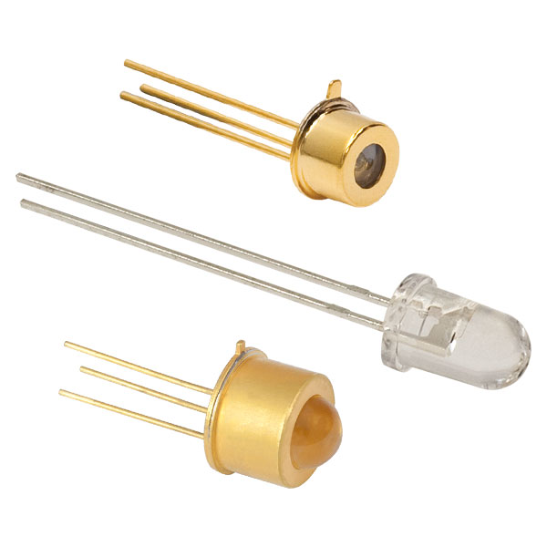 |
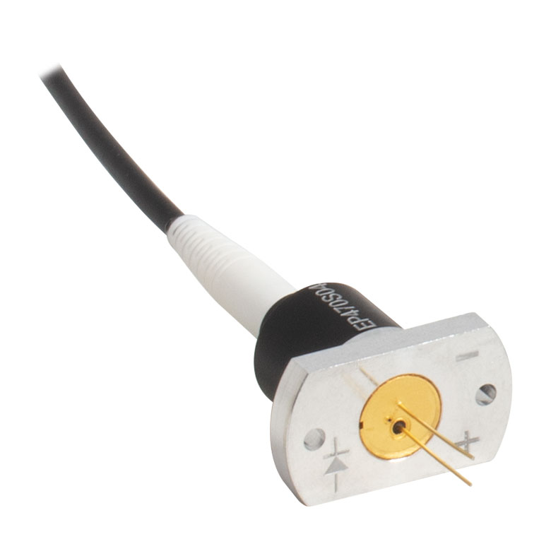 |
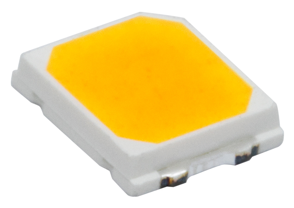 |
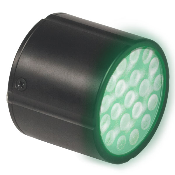 |
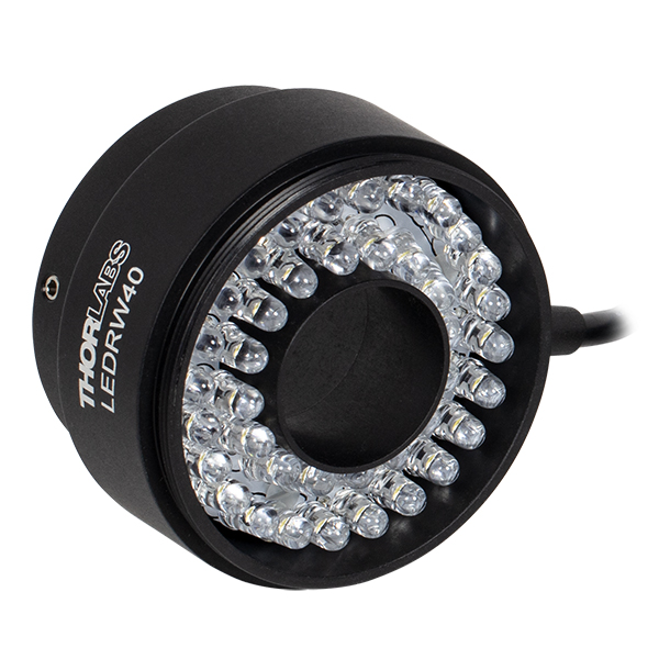 |
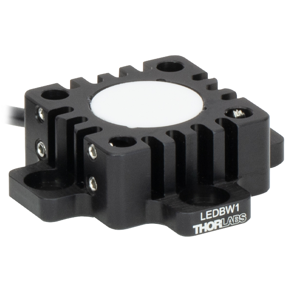 |
| Type | Unmounted LEDs | Pigtailed LEDs | LEDs in SMT Packages |
LED Arrays | LED Ring Light | Cage-Compatible Diffuse Backlight LED |
| Light Emitting Diode (LED) Selection Guide | ||||||
|---|---|---|---|---|---|---|
| Click Photo to Enlarge (Representative; Not to Scale) |
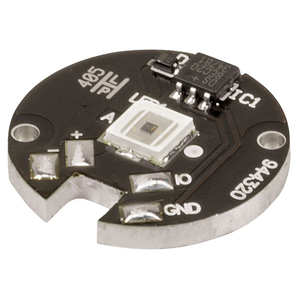 |
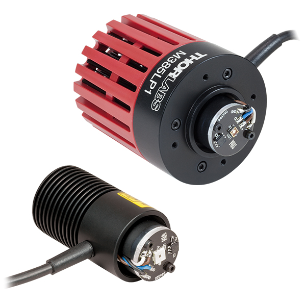 |
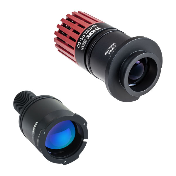 |
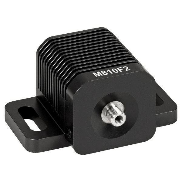 |
 |
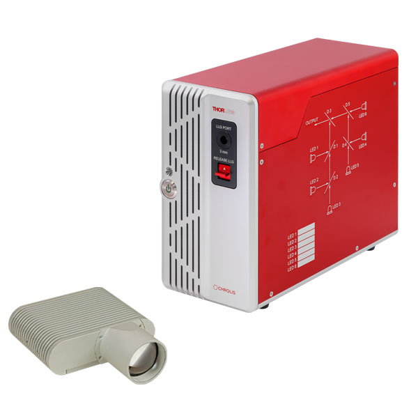 |
| Type | PCB- Mounted LEDs |
Heatsink- Mounted LEDs |
Collimated LEDs for Microscopyb | Fiber- Coupled LEDsc |
High-Power LEDs for Microscopy | Multi-Wavelength LED Source Optionsd |
Please note that our deep UV LEDs radiate intense UV light during operation. Precautions must be taken to prevent looking directly at the UV light, and UV light protective glasses must be worn to avoid eye damage. Exposure of the skin and other body parts to UV light should be avoided.
| Table G1.1 Specifications | ||||||||||
|---|---|---|---|---|---|---|---|---|---|---|
| Item # | Infoa | Nominal Wavelengthb |
Housing Typec |
LED Output Power (Min / Typ.)b,d |
Bandwidth (FWHM) |
Irradiancee | Max Current (CW) |
Forward Voltage (Typ.) |
Viewing Angle (Full Angle at Half Max) |
Recommended Driversf |
| M233L1 | 233 nm | 0.6 mW / 1.1 mWg | 8 nmg | 0.01 µW/mm2 d,g | 100 mAg | 6 Vd,g | 130° d,g | LEDD1B, DC40, UPLED, or DC2200 |
||
| M265L5 | 265 nm | 38.4 mW / 55.7 mWg | 11 nmg | 0.5 µW/mm2 d,g | 440 mAg | 6.9 Vd,g | 120° d,g | |||
| M275L4 | 275 nm | 45 mW / 80 mW | 11 nm | 0.8 µW/mm2 | 700 mA | 7.3 V | 118° | |||
| M280L6 | 280 nm | 78 mW / 114 mWg | 10 nmg | 1 µW/mm2 | 500 mAg | 6.26 Vg | 114° g,h | |||
| M300L4 | 300 nm | 26 mW / 32 mW | 20 nm | 0.3 µW/mm2 | 350 mA | 8.0 V | 130° | |||
| M310L1 | 308 nm | 38.5 mW / 56.5 mWg | 30 nmg | 0.76 µW/mm2 g | 600 mAg | 5 Vg | 120° g,h | LEDD1B, DC40, UPLED, DC2200, DC4100i, or DC4104i |
||
| M325L5 | 325 nm | 25 mW / 35 mW | 12 nm | 0.44 µW/mm2 (Max) | 600 mA | 5.2 V | 120° | LEDD1B, DC40, UPLED, or DC2200 |
||
| M340L5 | 340 nm | 45.5 mW / 69.2 mWg | 10 nmg | 0.6 µW/mm2 d,g | 600 mAg | 6.56 Vd,g | 120° g,h | |||
- Click on the info icon ( ) for complete specifications and LED spectrum.
- Due to variations in the manufacturing process and operating parameters such as temperature and current, the actual spectral output of any given LED will vary. Output plots and nominal wavelength specs are only intended to be used as a guideline.
- Click for LED Product Photo
- When Driven at the Max Current
- Irradiance is measured at a distance of 200 mm from the LED. Typical value unless otherwise noted
- Drivers for which max voltage and max current are greater than or equal to the forward voltage and max current of the LED, respectively. See the LED Drivers tab for the specifications of each driver.
- Measured at 25 °C.
- When Driven at a Current of 350 mA
- This is a four-channel driver and requires the DC4100-HUB connector hub to drive mounted LEDs.
Please note that our UV LEDs radiate intense UV light during operation. Precautions must be taken to prevent looking directly at the UV light, and UV light protective glasses must be worn to avoid eye damage. Exposure of the skin and other body parts to the UV light should be avoided.
| Table G2.1 Specifications | ||||||||||
|---|---|---|---|---|---|---|---|---|---|---|
| Item # | Infoa | Nominal Wavelengthb |
Housing Typec |
LED Output Power (Min / Typ.)b,d |
Bandwidth (FWHM) |
Irradiance (Typ.)e |
Max Current (CW) |
Forward Voltage (Typ.) |
Viewing Angle (Full Angle at Half Max) |
Recommended Driversf |
| M365L3 | 365 nm | 880 mW / 1290 mW | 9 nm | 14.4 µW/mm2 | 1000 mA | 3.85 V | 120° | LEDD1B, DC40 UPLED, DC2200 DC4100g, or DC4104g |
||
| M365LP1 | 365 nm | 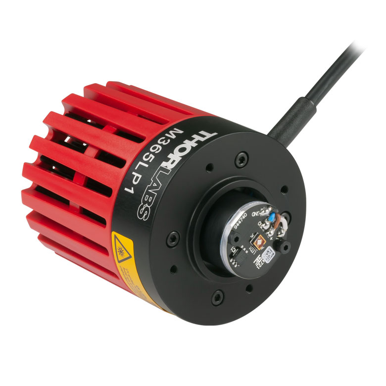 |
1350 mW / 2000 mW | 9 nm | 21.0 µW/mm2 | 1700 mA | 4.0 V | 120° | DC40 or DC2200 | |
| M375L4 | 375 nm | 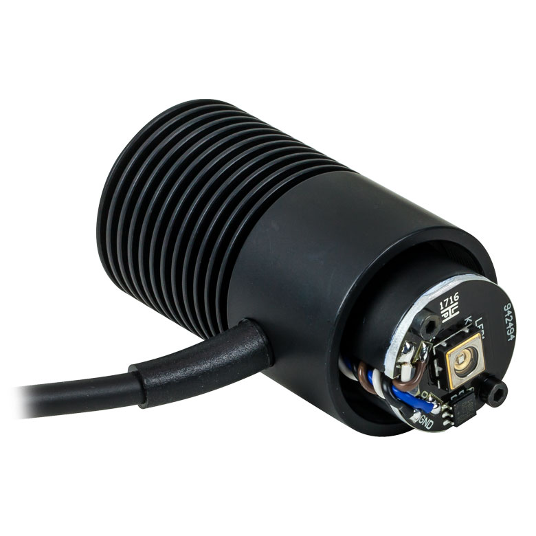 |
1270 mW / 1540 mW | 9 nm | 19.2 µW/mm2 | 1400 mA | 3.6 V | 130° | ||
| M385L3 | 385 nm | 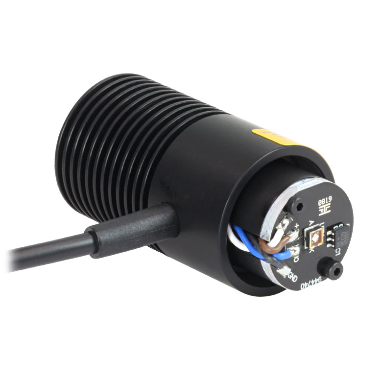 |
1240 mW / 1780 mW | 11 nm | 19.9 µW/mm2 | 1000 mA | 3.7 V | 120° | LEDD1B, DC40 UPLED, DC2200 DC4100g, or DC4104g |
|
| M385LP1 | 385 nm | 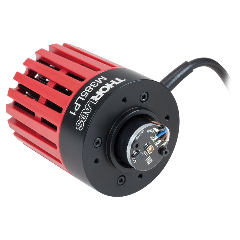 |
1650 mW / 1830 mW | 12 nm | 23.3 µW/mm2 | 1700 mA | 3.9 V | 120° | DC40 or DC2200 | |
| M395L4 | 395 nm | 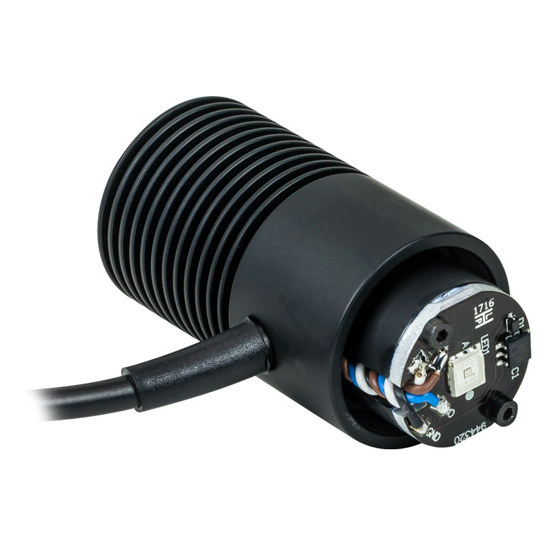 |
400 mW / 535 mW | 16 nm | 6.7 µW/mm2 | 500 mA | 4.5 V | 126° | LEDD1B, DC40 UPLED, DC2200 DC4100g, or DC4104g |
|
| M395L5 | 395 nm | 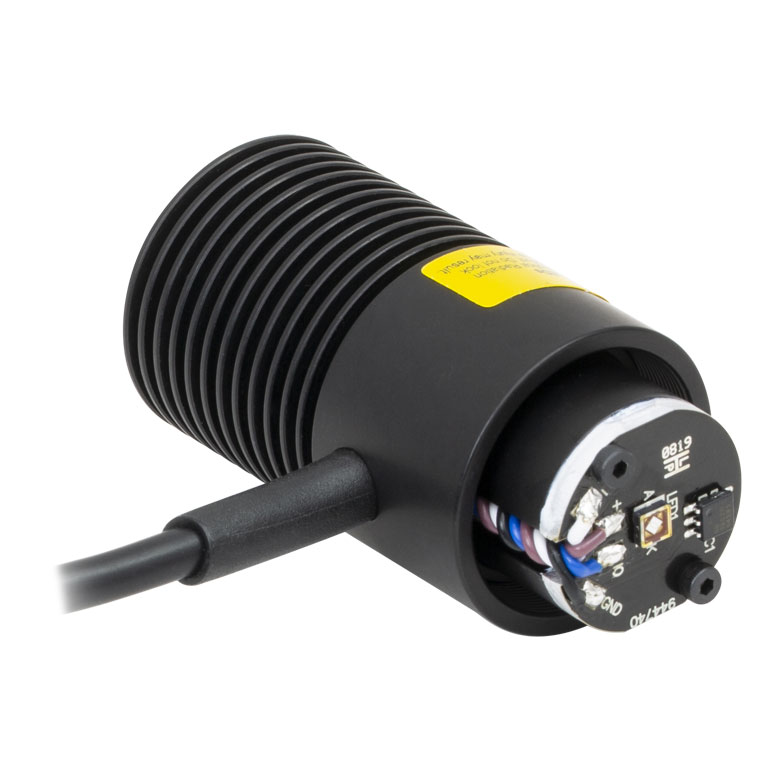 |
1130 mW / 1630 mW | 11 nm | 16.9 µW/mm2 | 1000 mA | 3.7 V | 120° | ||
| M395LP1 | 395 nm | 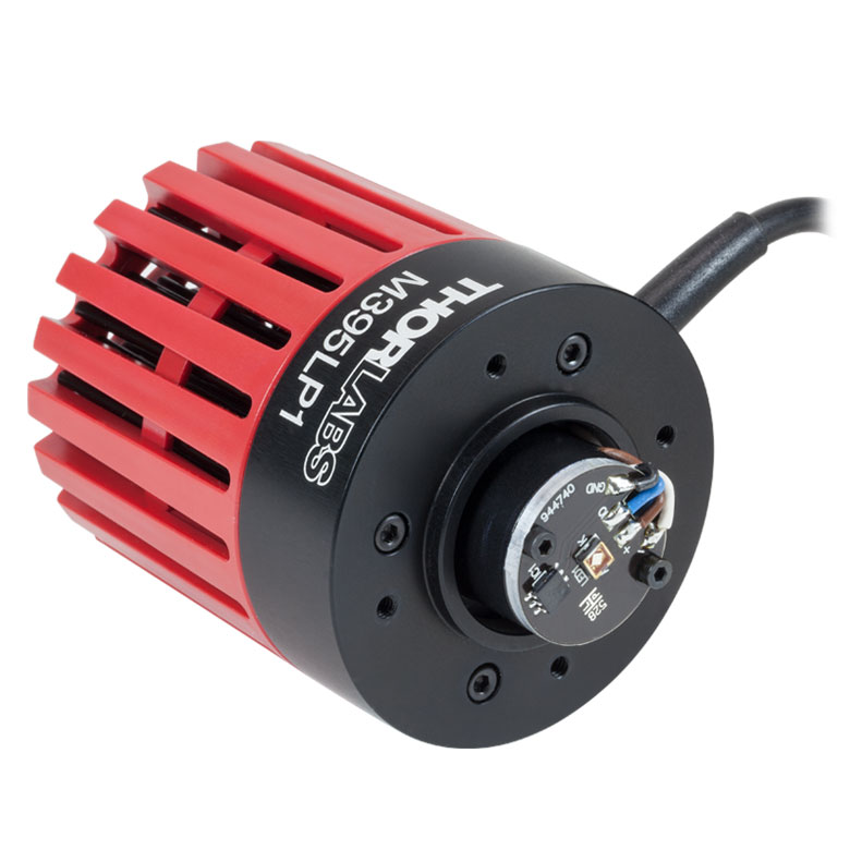 |
1420 mW / 2050 mW | 11 nm | 22.8 µW/mm2 | 1400 mA | 4.0 V | 120° | DC40 or DC2200 | |
| M405L4 | 405 nm | 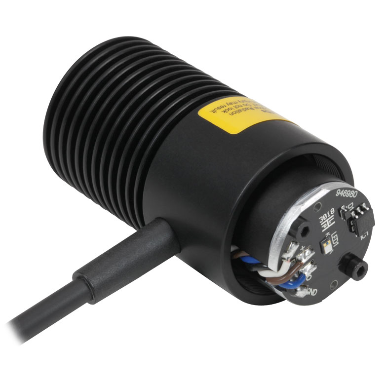 |
1000 mW / 1300 mW | 12.5 nm | 14.53 µW/mm2 | 1000 mA | 3.4 V | 140° | LEDD1B, DC40 UPLED, DC2200 DC4100g, or DC4104g |
|
| M405LP1 | 405 nm | 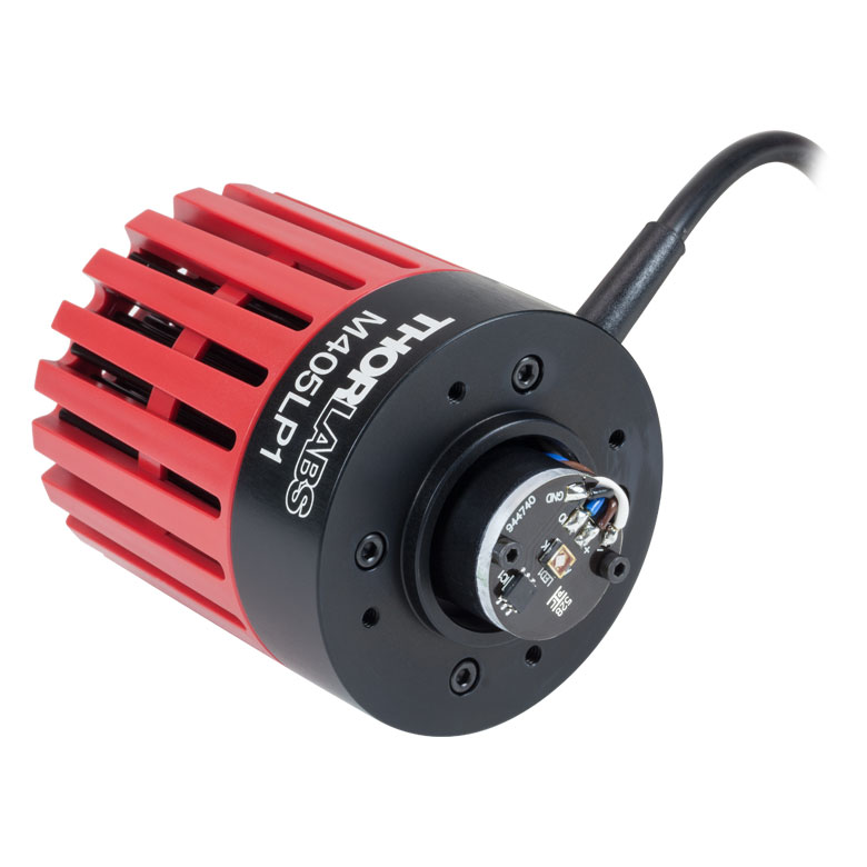 |
1200 mW / 1700 mW | 12 nm | 24.6 µW/mm2 | 1400 mA | 3.45 V | 120° | DC40 or DC2200 | |
- Click on the info icon ( ) for complete specifications and LED spectrum.
- Due to variations in the manufacturing process and operating parameters such as temperature and current, the actual spectral output of any given LED will vary. Output plots and nominal wavelength specs are only intended to be used as a guideline.
- Click for LED Product Photo
- When Driven at the Max Current
- Irradiance is measured at a distance of 200 mm from the LED.
- Drivers for which max voltage and max current are greater than or equal to the forward voltage and max current of the LED, respectively. See the LED Drivers tab for the specifications of each driver.
- This is a four-channel driver and requires the DC4100-HUB connector hub to drive mounted LEDs.
Please note that the 415 nm (violet), 430 nm (violet), and 450 nm (royal blue) LEDs radiate intense UV light during operation. Precautions must be taken to prevent looking directly at the UV light, and UV light protective glasses must be worn to avoid eye damage. Exposure of the skin and other body parts to the UV light should be avoided.
| Table G3.1 Specifications | ||||||||||
|---|---|---|---|---|---|---|---|---|---|---|
| Item # | Infoa | Nominal Wavelengthb,c |
Housing Typed |
LED Output Power (Min / Typ.)b,e |
Bandwidth (FWHM) |
Irradiance (Typ.)f |
Max Current (CW) |
Forward Voltageg |
Viewing Angle (Full Angle at Half Max) |
Recommended Driversh |
| M415L4i | 415 nm (Violet) | 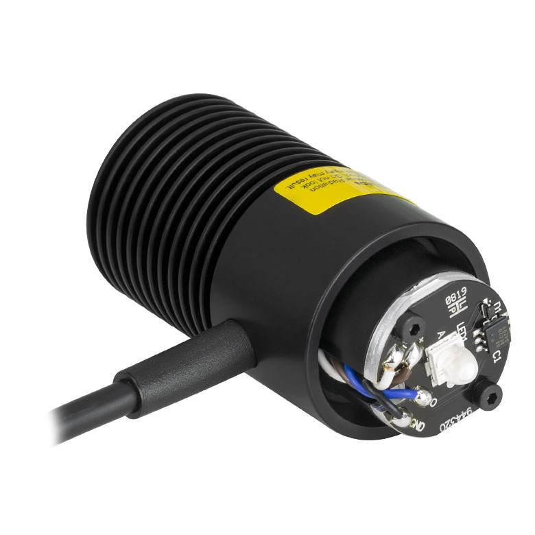 |
1310 mW / 1550 mW | 14 nm | 15.6 µW/mm2 | 1500 mA | 3.1 V | 138° | DC40 or DC2200 | |
| M415LP1i | 415 nm (Violet) | 1640 mW / 1940 mW | 14 nm | 19.5 µW/mm2 | 2000 mA | 3.15 V | 138° | |||
| M430L5 | 430 nm (Violet) | 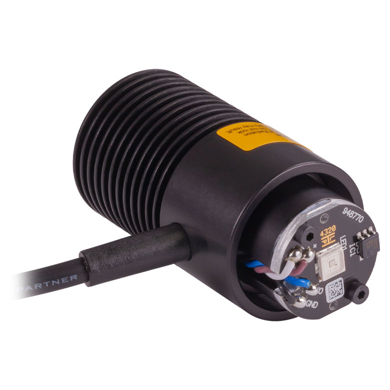 |
529.2 mW / 757.6 mW | 17 nm | 25.7 µW/mm2 | 500 mA | 3.66 V | 126° | LEDD1B, DC40, UPLED, DC2200, DC4100j, or DC4104j | |
| M450LP2 | 450 nm (Royal Blue) | 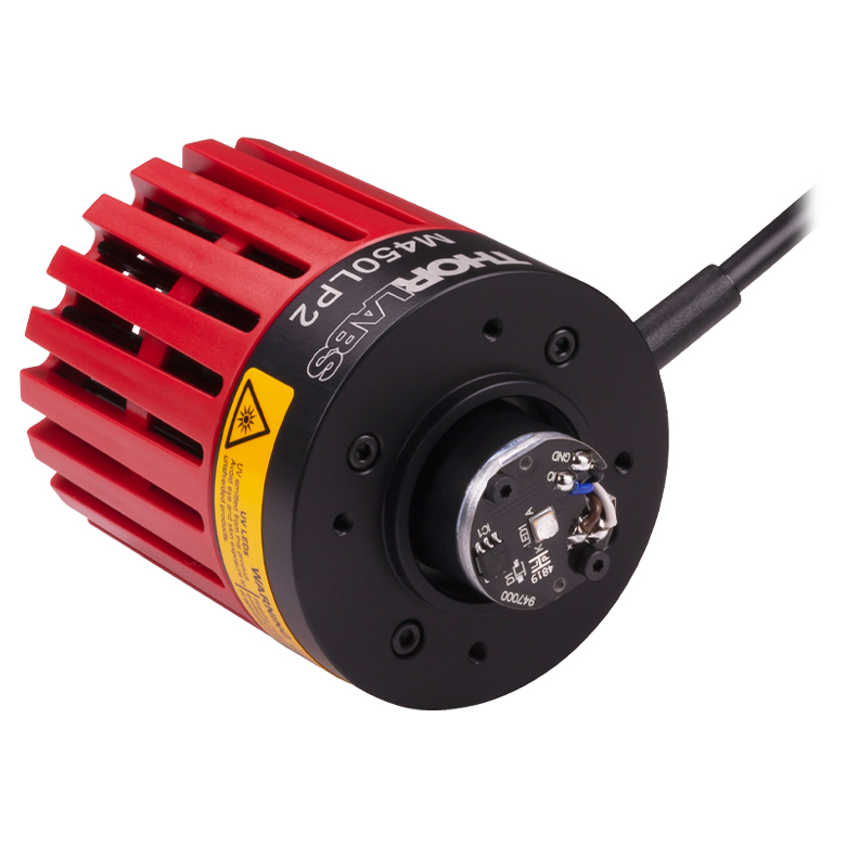 |
2118.1 mW / 3041.5 mWk | 18 nmj | 34.2 µW/mm2 e,k | 2000 mAk | 3.2 Ve,k | 120° k,l | DC40 or DC2200 | |
| M455L4 | 455 nm (Royal Blue) | 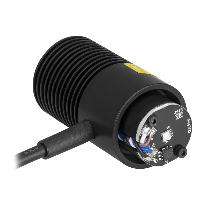 |
1150 mW / 1445 mW | 18 nm | 32 µW/mm2 | 1000 mA | 3.25 V | 80° | LEDD1B, DC40, UPLED, DC2200, DC4100j, or DC4104j | |
| M470L5 | 470 nm (Blue) | |
809 mW / 1161.7 mW | 28 nm | 21.4 µW/mm2 | 1000 mA | 3.8 V | 80° | ||
| M490L4 | 490 nm (Blue) |  |
205 mW / 240 mW | 26 nm | 2.5 µW/mm2 | 350 mA | 3.8 V | 128° | ||
| M505L5 | 508 nm (Green) | 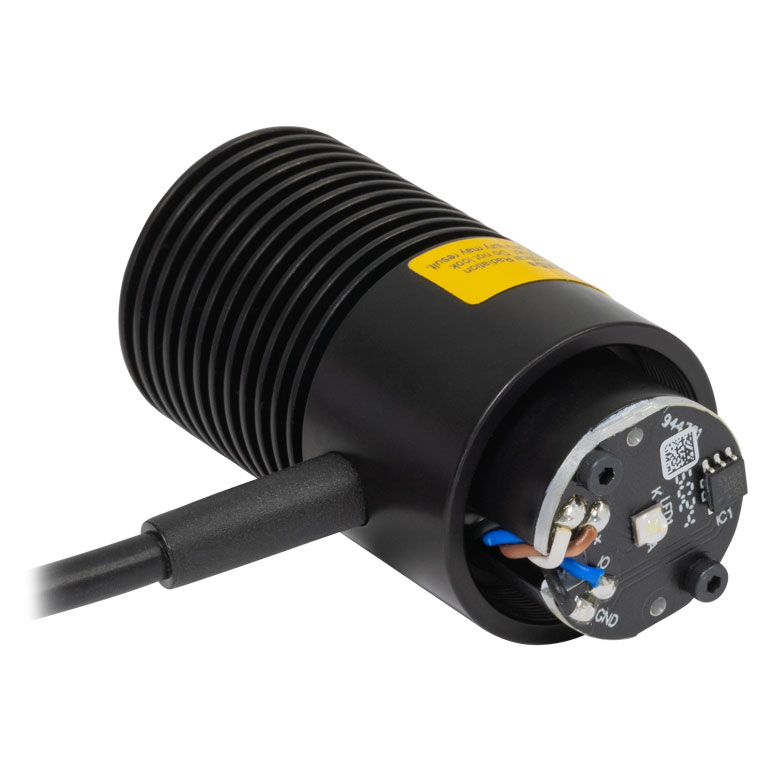 |
550 mW / 810 mWk | 29 nme,k | 9.0 µW/mm2 e,k | 1200 mAk | 3.4 Ve,k | 120°e,k | LEDD1B, DC40, UPLED, DC2200, DC4100j,m, or DC4104j,m | |
| M530L4 | 530 nm (Green) | 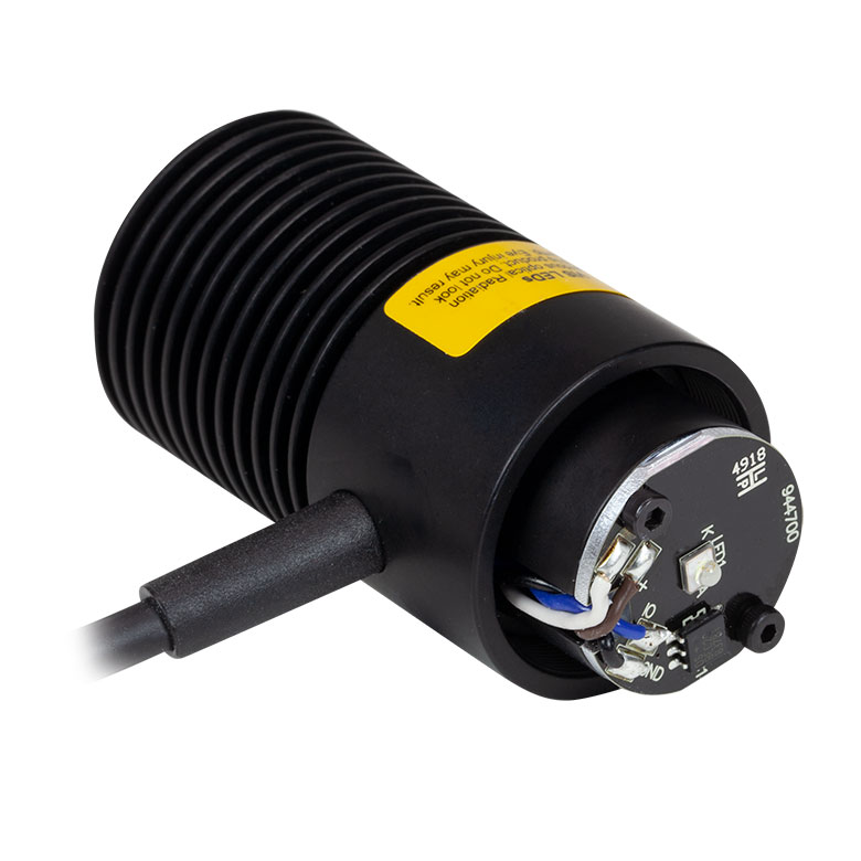 |
370 mW / 480 mW | 35 nm | 9.46 µW/mm2 | 1000 mA | 3.6 V | 80° | LEDD1B, DC40, UPLED, DC2200, DC4100j, or DC4104j | |
| MINTL5 | 554 nm (Mint) | 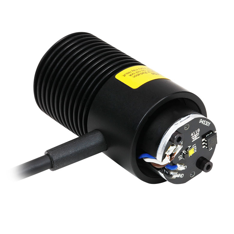 |
650 mW / 815 mW | - | 12.4 µW/mm2 | 1225 mA | 3.5 V | 120° | DC40, DC2200, LEDD1Bm, or UPLEDm | |
| M565L3n | 565 nm (Lime) | 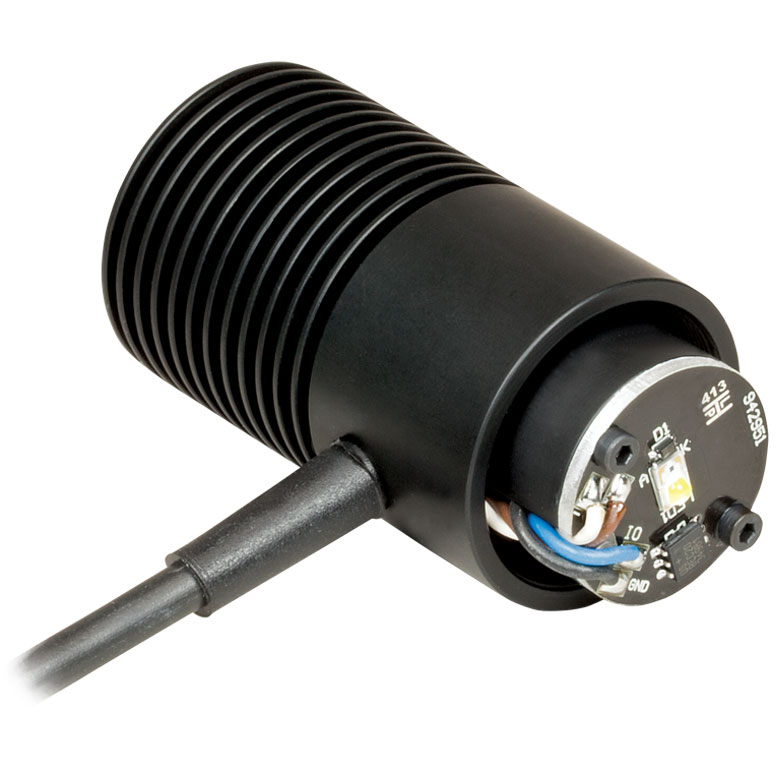 |
880 mW / 979 mW | 104 nm | 11.7 µW/mm2 | 1000 mA | 3.1 V (Max) | 125° | LEDD1B, DC40, UPLED, DC2200, DC4100j, or DC4104j | |
- Click on the info icon ( ) for complete specifications and LED spectrum.
- Due to variations in the manufacturing process and operating parameters such as temperature and current, the actual spectral output of any given LED will vary. Output plots and nominal wavelength specs are only intended to be used as a guideline.
- The nominal wavelength indicates the wavelength at which the LED appears brightest to the human eye. The nominal wavelength for visible LEDs may not correspond to the peak wavelength as measured by a spectrometer.
- Click for LED Product Photo
- When Driven at the Max Current
- Irradiance is measured at a distance of 200 mm from the LED.
- Values are typical unless otherwise stated.
- Drivers for which max voltage and max current are greater than or equal to the forward voltage and max current of the LED, respectively. See the LED Drivers tab for the specifications of each driver.
- This LED radiates intense UV light during operation. Precautions must be taken to prevent looking directly at the UV light and UV light protective glasses must be worn to avoid eye damage. Exposure of the skin and other body parts to the UV light should be avoided.
- This is a four-channel driver and requires the DC4100-HUB connector hub to drive mounted LEDs.
- Measured at 25 °C
- When Driven at 700 mA Current
- Due to the maximum current that can be provided by this driver, this mounted LED can be driven near, but not at, full power.
- This LED is phosphor-converted and may not turn off completely when modulated above 10 kHz at duty cycles below 50%.
| Table G4.1 Specifications | ||||||||||
|---|---|---|---|---|---|---|---|---|---|---|
| Item # | Infoa | Nominal Wavelengthb,c |
Housing Typed |
LED Output Power (Min / Typ.)b,e |
Bandwidth (FWHM) |
Irradiance (Typ.)f |
Max Current (CW) |
Forward Voltage (Typ.) |
Viewing Angle (Full Angle at Half Max) |
Recommended Driversg |
| M590L4 | 590 nm (Amber) | 230 mW / 300 mW | 15 nm | 6.0 µW/mm2 | 1000 mA | 2.5 V | 80° | LEDD1B, DC40, UPLED, DC2200, DC4100h, or DC4104h | ||
| M595L4i | 595 nm (Amber) | 820 mW / 1217 mW | 64 nm | 13.5 µW/mm2 | 1500 mA | 3.0 V | 120° | DC40 or DC2200 | ||
| M617L5 | 617 nm (Orange) | 737.4 mW / 1006.2 mWj | 16 nmj | 19.4 µW/mm2 e,j | 1000 mAj | 2.9 Ve,j | 80° j,k | LEDD1B, DC40, UPLED, DC2200, DC4100h, or DC4104h | ||
| M625L4 | 625 nm (Red) | 700 mW / 920 mW | 17 nm | 21.9 µW/mm2 | 1000 mA | 2.5 V | 80° | |||
| M660L4 | 660 nm (Deep Red) | 940 mW / 1050 mW | 20 nm | 20.88 µW/mm2 | 1200 mA | 2.6 V | 100° | LEDD1B, DC40, UPLED, or DC2200 | ||
| M680L5 | 680 nm (Deep Red) | 380 mW / 550 mWj | 20 nme,j | 6.2 µW/mm2 e,j | 600 mAj | 2.4 Ve,j | 128°e,j | LEDD1B, DC40, UPLED, DC2200, DC4100h, or DC4104h | ||
| M700L5 | 700 nm (Deep Red) | 290 mW / 410 mW | 19 nm | 4.6 µW/mm2 | 500 mA | 2.1 V | 128° | |||
| M730L6 | 727 nm (Far Red) | 780 mW / 1130 mW | 38 nm | 13.8 µW/mm2 | 1000 mA | 2.5 V | 120° | |||
- Click on the info icon ( ) for complete specifications and LED spectrum.
- Due to variations in the manufacturing process and operating parameters such as temperature and current, the actual spectral output of any given LED will vary. Output plots and nominal wavelength specs are only intended to be used as a guideline.
- The nominal wavelength indicates the wavelength at which the LED appears brightest to the human eye. The nominal wavelength for visible LEDs may not correspond to the peak wavelength as measured by a spectrometer.
- Click for LED Product Photo
- When Driven at the Max Current
- Irradiance is measured at a distance of 200 mm from the LED.
- Drivers for which max voltage and max current are greater than or equal to the forward voltage and max current of the LED, respectively. See the LED Drivers tab for the specifications of each driver.
- This is a four-channel driver and requires the DC4100-HUB connector hub to drive mounted LEDs.
- This LED is phosphor-converted and may not turn off completely when modulated above 10 kHz at duty cycles below 50%.
- Measured at 25 °C
- When Driven at the Current of 350 mA
| Table G5.1 Specifications | ||||||||||
|---|---|---|---|---|---|---|---|---|---|---|
| Item # | Infoa | Nominal Wavelengthb |
Housing Typec |
LED Output Power (Min / Typ.)b,d |
Bandwidth (FWHM) |
Irradiance (Typ.)e |
Max Current (CW) |
Forward Voltage (Typ.) |
Viewing Angle (Full Angle at Half Max) |
Recommended Driversf |
| M780L3 | 780 nm | 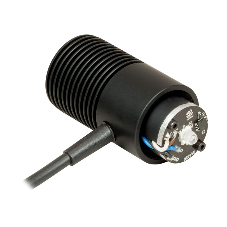 |
200 mW / 300 mW | 28 nm | 47.3 µW/mm2 | 800 mA | 2.0 V | 20° | LEDD1B, DC40, UPLED, DC2200, DC4100g, or DC4104g |
|
| M780LP1 | 780 nm | 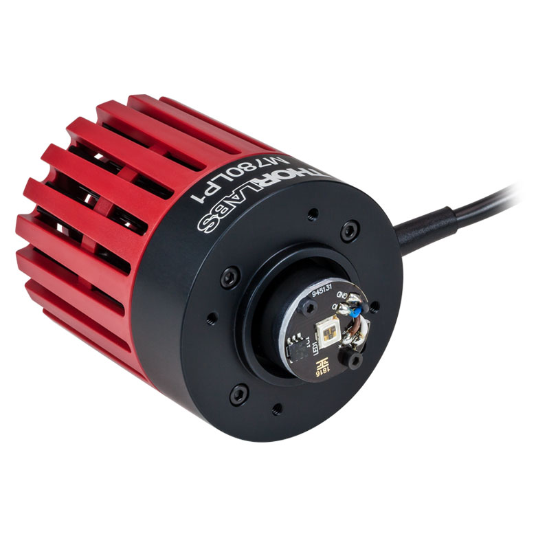 |
800 mW / 950 mW | 30 nm | 13.3 µW/mm2 | 800 mA | 6.6 V | 120° | LEDD1B, DC40, UPLED, or DC2200 | |
| M810L5 | 810 nm |  |
810 mW / 1190 mWh | 30 nmh | 15.9 µW/mm2 d,h | 1000 mAh | 3.6 Vd,h | 128° d,h | LEDD1B, DC40, UPLED, DC2200, DC4100g, or DC4104g |
|
| M850L3 | 850 nm |  |
900 mW / 1100 mW | 30 nm | 22.9 µW/mm2 | 1200 mA | 2.95 V | 90° | LEDD1B, DC40, UPLED, or DC2200 | |
| M850LP1 | 850 nm |  |
1400 mW / 1600 mW | 30 nm | 19.4 µW/mm2 | 1500 mA | 3.85 V | 150° | DC40 or DC2200 | |
| M880L3 | 880 nm | 300 mW / 350 mW | 50 nm | 5.6 µW/mm2 | 1000 mA | 1.7 V | 132° | LEDD1B, DC40, UPLED, DC2200, DC4100g, or DC4104g | ||
| M940L3 | 940 nm | 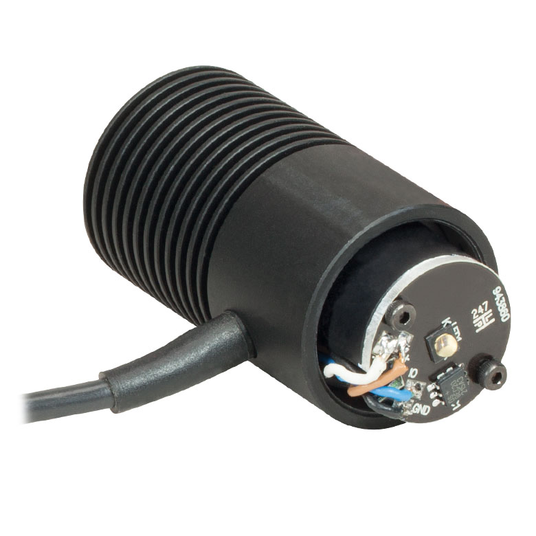 |
800 mW / 1000 mW | 37 nm | 19.1 µW/mm2 | 1000 mA | 2.75 V | 90° | ||
| M970L4 | 970 nm | 600 mW / 720 mW | 60 nm | 7.4 µW/mm2 | 1000 mA | 1.9 V | 130° | |||
| M1050L2 | 1050 nm | 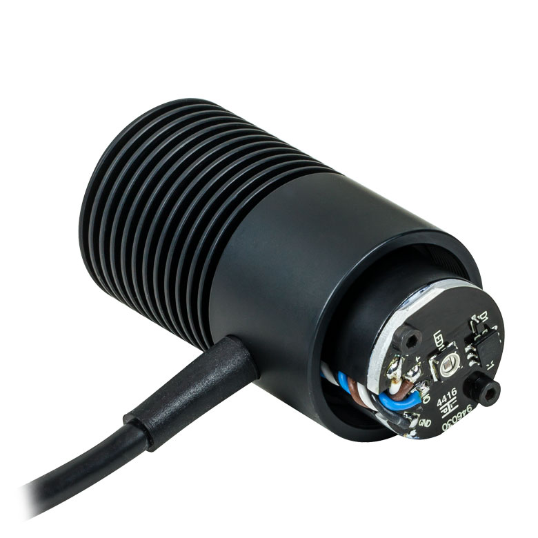 |
50 mW / 70 mW | 60 nm | 1.9 µW/mm2 | 700 mA | 1.5 V | 120° | ||
| M1050L4 | 1050 nm | |
160 mW / 210 mW | 37 nm | 3.7 µW/mm2 | 600 mA | 1.4 V | 128° | ||
| M1100L1 | 1100 nm | 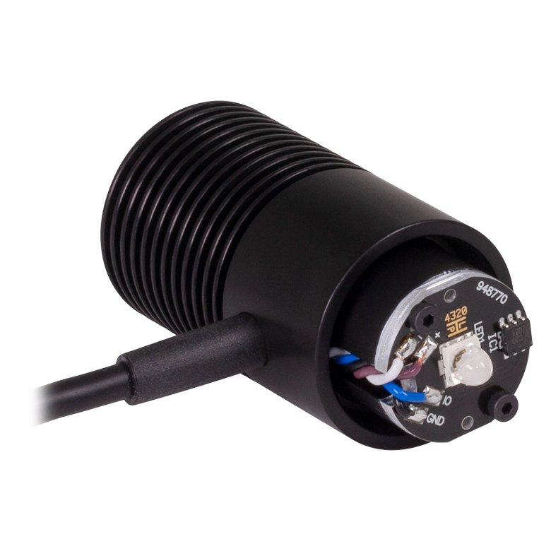 |
168 mW / 252 mWh | 50 nmh | 18.1 µW/mm2 d,h | 1000 mAh | 1.4 Vd,h | 18° h,i | ||
| M1200L4 | 1200 nm | 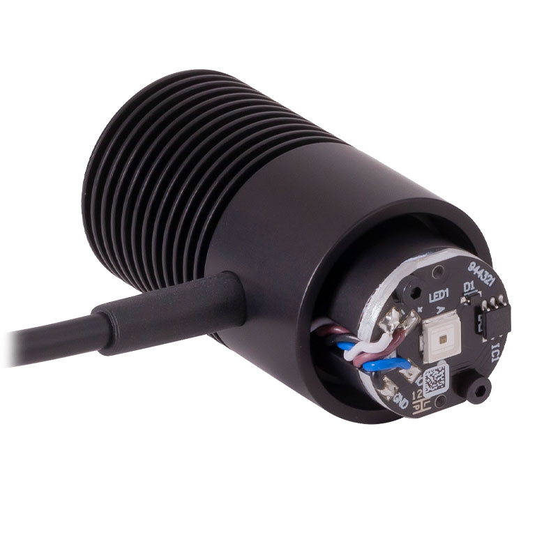 |
136 mW / 200 mWh | 65 nmh | 2.6 µW/mm2 d,h | 1000 mAh | 2.2 Vd,h | 130° d,h | ||
| M1300L3 | 1300 nm | 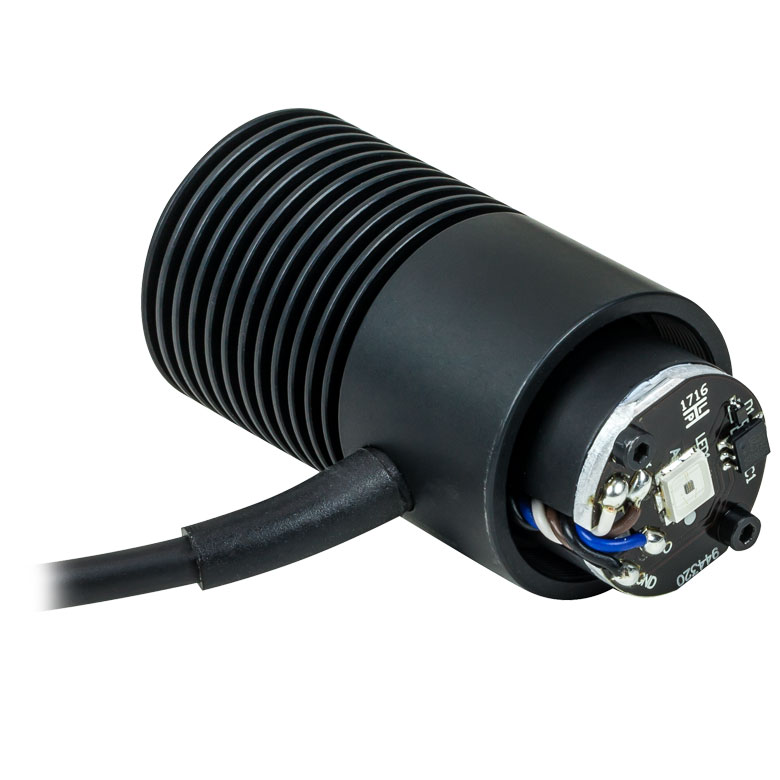 |
25 mW / 30 mW | 80 nm | 0.6 µW/mm2 | 500 mA | 1.4 V | 134° | ||
| M1300L4 | 1300 nm | 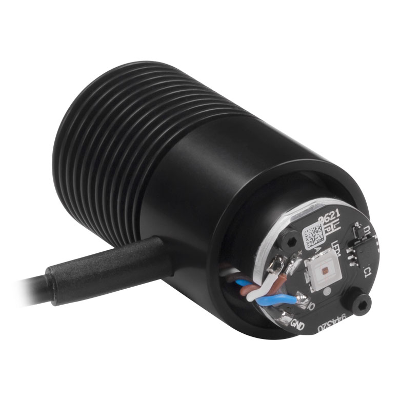 |
122.8 mW / 182.1 mWh | 80 nmh | 1.6 µW/mm2 d,h | 1000 mAh | 1.7 Vd,h | 130° h | ||
| M1450L4 | 1450 nm | 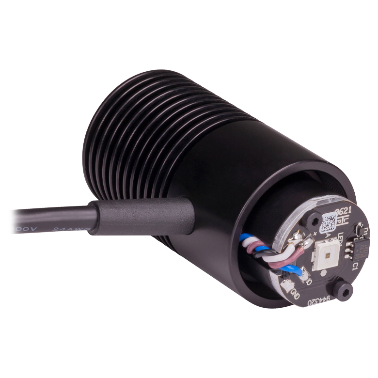 |
81.8 mW / 120.7 mW | 95 nm | 1.5 µW/mm2 | 1000 mA | 1.88 V | 130° | ||
| M1550L4 | 1550 nm | 46 mW / 70 mWh | 120 nmh | 1.1 µW/mm2 d,h | 1000 mAh | 1.3 Vd,h | 128° h,i | |||
| M1650L4 | 1650 nm | 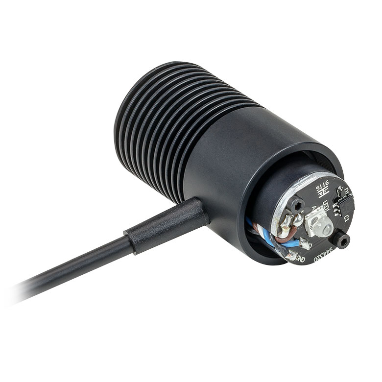 |
13 mW / 16 mW | 120 nm | 1.2 µW/mm2 | 600 mA | 1.1 V | 20° | ||
| M1900L1 | 1900 nm |  |
10 mW / 15 mWh | 120 nmd,h | 2.2 µW/mm2 d,h | 1000 mAh | 1.2 Vd,h | 18° d,h | ||
- Click on the info icon ( ) for complete specifications and LED spectrum.
- Due to variations in the manufacturing process and operating parameters such as temperature and current, the actual spectral output of any given LED will vary. Output plots and nominal wavelength specs are only intended to be used as a guideline.
- Click for LED Product Photo
- When Driven at the Max Current
- Irradiance is measured at a distance of 200 mm from the LED.
- Drivers for which max voltage and max current are greater than or equal to the forward voltage and max current of the LED, respectively. See the LED Drivers tab for the specifications of each driver.
- This is a four-channel driver and requires the DC4100-HUB connector hub to drive mounted LEDs.
- Measured at 25 °C
- When Driven at a Current of 100 mA
| Table G6.1 Specifications | |||||||||
|---|---|---|---|---|---|---|---|---|---|
| Item # | Infoa | Nominal Wavelengthb |
Housing Typec |
LED Output Power (Min / Typ.)d,e |
Bandwidth (FWHM)d |
Max Current (CW)d |
Forward Voltage (Typ.)d,e |
Viewing Angle (Full Angle at Half Max) |
Recommended Driversf |
| M3400L1 | 3400 nm | 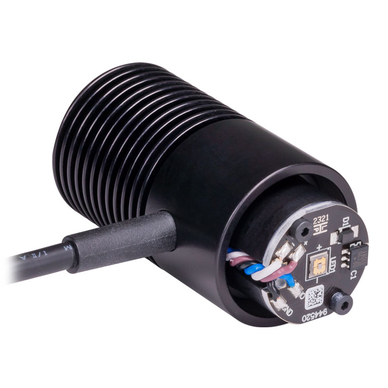 |
2.2 mW / 3.3 mW | 800 nm | 200 mA | 4.1 V | 130° | LEDD1B, DC40, UPLED, DC2200, DC4100g, or DC4104g |
|
| M4300L1 | 4300 nm | 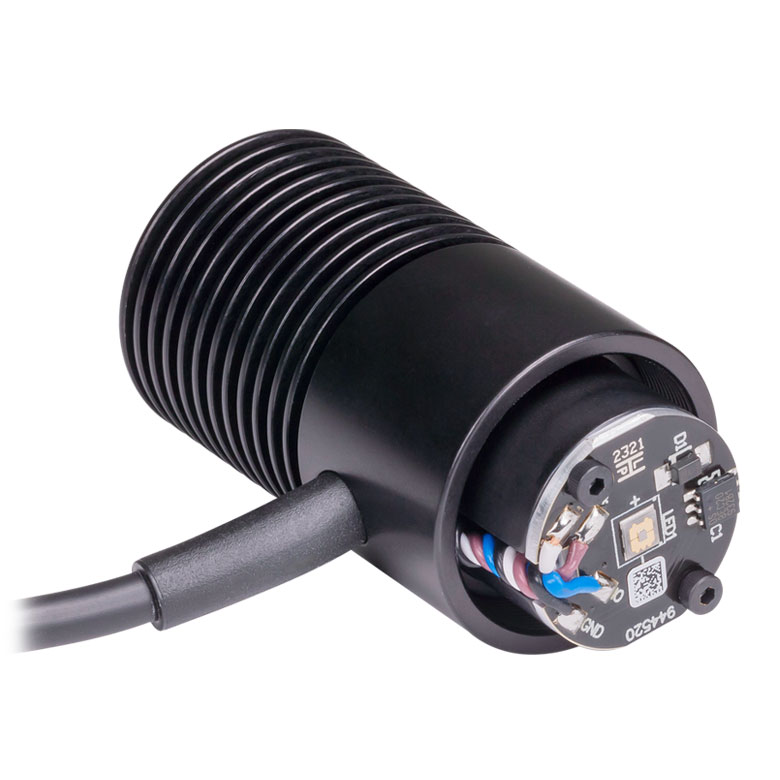 |
1.1 mW / 1.67 mW | 800 nm | 200 mA | 3.9 V | 130° | ||
| M5200L1 | 5200 nm | 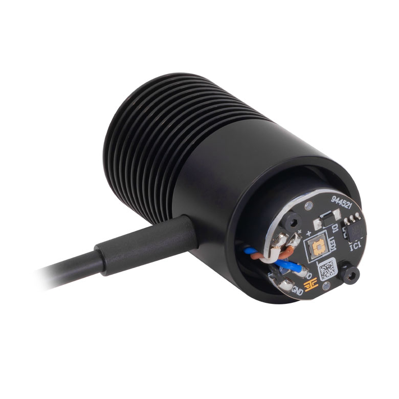 |
0.8 mW / 1.3 mW | 800 nm | 200 mA | 4 V | 130°d,e | ||
- Click on the info icon ( ) for complete specifications and LED spectrum.
- Due to variations in the manufacturing process and operating parameters such as temperature and current, the actual spectral output of any given LED will vary. Output plots and nominal wavelength specs are only intended to be used as a guideline.
- Click for LED Product Photo
- Measured at 25 °C
- When Driven at the Maximum Current
- Drivers for which max voltage and max current are greater than or equal to the forward voltage and max current of the LED, respectively. See the LED Drivers tab for the specifications of each driver.
- This is a four-channel driver and requires the DC4100-HUB connector hub to drive mounted LEDs.
Our dual-peak LED was designed for applications requiring illumination in both red and blue portions of the spectrum, such as horticulture. This purple LED features dual peaks at 455 nm and 640 nm, respectively, to stimulate photosynthesis (see graph to compare the absorption peaks of photosynthesis pigments with the LED spectrum). The LED was designed to maintain the red/blue ratio of the emission spectrum over its lifetime to provide high uniformity of plant growth.
| Table G7.1 Specifications | ||||||||||
|---|---|---|---|---|---|---|---|---|---|---|
| Item # | Infoa | Nominal Wavelengthb |
Housing Typec |
LED Output Power (Min / Typ.)b,d |
Bandwidth (FWHM) |
Irradiance (Typ.)e |
Max Current (CW) |
Forward Voltage (Typ.) |
Viewing Angle (Full Angle at Half Max) |
Recommended Driversf |
| MPRP1L4g | 455 nm (12.5%h) / 640 nm | 275 mW / 325 mW | N/A | 3.7 µW/mm2 | 300 mA | 3.1 V | 115° | LEDD1B, DC40, UPLED, DC2200, DC4100i, or DC4104i | ||
- Click on the info icon ( ) for complete specifications and LED spectrum.
- Due to variations in the manufacturing process and operating parameters such as temperature and current, the actual spectral output of any given LED will vary. Output plots and nominal wavelength specs are only intended to be used as a guideline.
- Click for LED Product Photo
- When Driven at the Max Current
- Irradiance is measured at a distance of 200 mm from the LED.
- Drivers for which max voltage and max current are greater than or equal to the forward voltage and max current of the LED, respectively. See the LED Drivers tab for the specifications of each driver.
- This LED is phosphor-converted and may not turn off completely when modulated above 10 kHz at duty cycles below 50%.
- Percentage of LED intensity that emits in the blue portion of the spectrum, from 400 nm to 525 nm. Click on the info icon for details.
- This is a four-channel driver and requires the DC4100-HUB connector hub to drive mounted LEDs.
Our warm, neutral, and cold white LEDs feature broad spectra that span several hundred nanometers. The difference in appearance among these LEDs can be described using the correlated color temperature, which indicates that the LEDs color appearance is similar to a black body radiator at that temperature. In general, warm white LEDs offer a spectrum similar to a tungsten source, while cold white LEDs have a stronger blue component to the spectrum; neutral white LEDs provide a more even illumination spectrum over the visible range than warm white or cold white LEDs. Cold white LEDs are more suited for fluorescence microscopy applications or cameras with white balancing, because of a higher intensity at most wavelengths compared to warm white LEDs. Neutral white LEDs are ideal for horticultural applications.
| Table G8.1 Specifications | ||||||||||
|---|---|---|---|---|---|---|---|---|---|---|
| Item # | Infoa | Correlated Color Temperatureb |
Housing Typec |
LED Output Power (Min / Typ.)b,d |
Bandwidth (FWHM) |
Irradiance (Typ.)e |
Max Current (CW) |
Forward Voltage (Typ.) |
Viewing Angle (Full Angle at Half Max) |
Recommended Driversf |
| MWWHL4g | 3000 K (Warm White) |
570 mW / 640 mW | N/A | 9.4 µW/mm2 | 1000 mA | 3.0 V | 120° | LEDD1B, DC40, UPLED, DC2200, DC4100h, or DC4104h |
||
| MWWHLP2g | 3000 K (Warm White) |
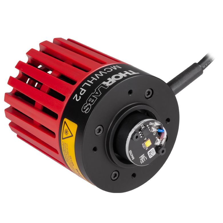 |
1713 mW / 2499 mWi | N/A | 27.2 µW/mm2 d,i | 700 mAi | 12.1 Vd,i | 135° i | DC40 or DC2200 | |
| MWUVL1g | 4000 Kj (Neutral White) |
235 mW / 338 mWi | N/A | 4.0 µW/mm2 d.i | 125 mA | 6.3 V | 120° k | LEDD1B, DC40, UPLED, or DC2200 | ||
| MNWHLP1g | 4000 K (Neutral White) |
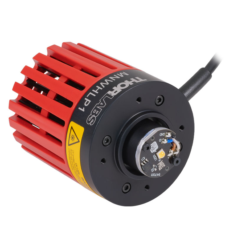 |
1400 mW / 2040 mWi | N/A | 25 µW/mm2 d,i | 2000 mAi | 3.1 Vd,i | 120°d,i | DC40 or DC2200 | |
| MNWHL4g | 4900 K (Neutral White) |
740 mW / 880 mW | N/A | 7.7 µW/mm2 | 1225 mA | 2.9 V | 150° | DC40, DC2200, LEDD1Bl, or UPLEDl | ||
| MCWHL7g | 6500 K (Cold White) |
930 mW / 1370 mW | N/A | 25.9 µW/mm2 d | 1300 mA | 3.3 V | 80° | DC40 or DC2200 | ||
| MCWHLP2g | 6500 K (Cold White) |
|
942 mW / 1353 mWi | N/A | 11.8 µW/mm2 d,i | 1300 mA | 4.51 V | 150° | ||
| MCWHL8g | 6500 K (Cold White) |
1300.9 mW / 1882.0 mWi |
N/A | 22.5 µW/mm2 d,i | 1400 mAi | 3.6 V d,i | 125° i | |||
| MCWHLP3g | 6500 K (Cold White) |
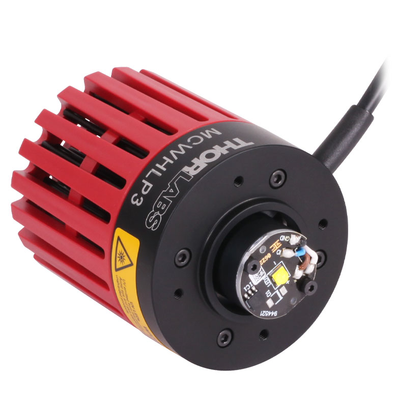 |
2064.8 mW / 2998.0 mWi | N/A | 33.3 µW/mm2 d,i | 700 mAi | 12.9 Vd,i | 135° i | ||
- Click on the info icon ( ) for complete specifications and LED spectrum.
- Due to variations in the manufacturing process and operating parameters such as temperature and current, the actual spectral output of any given LED will vary. Output plots and correlated color temperature specs are only intended to be used as a guideline.
- Click for LED Product Photo
- When Driven at the Max Current
- Irradiance is measured at a distance of 200 mm from the LED.
- Drivers for which max voltage and max current are greater than or equal to the forward voltage and max current of the LED, respectively. See the LED Drivers tab for the specifications of each driver.
- These LEDs are phosphor-converted and may not turn off completely when modulated above 10 kHz at duty cycles below 50%.
- This is a four-channel driver and requires the DC4100-HUB connector hub to drive mounted LEDs.
- Measured at 25 °C
- Neutral White LED Spectrum with a Peak at 406 nm
- When Driven with a Pulsed Forward Current of 75 mA
- Due to the maximum current that can be provided by this driver, this mounted LED can be driven near, but not at, full power.
The MBB1L3 broadband LED has a relatively flat spectral emission over a wide wavelength range. Its 10 dB bandwidth ranges between 470 nm and 850 nm. The MBB2L1 and MBB2LP1 broadband LEDs feature a spectrum with peaks at approximately 770 nm, 860 nm, and 940 nm.
| Table G9.1 Specifications | ||||||||||
|---|---|---|---|---|---|---|---|---|---|---|
| Item # | Infoa | Wavelengthb | Housing Typec |
LED Output Power (Min / Typ.)b,d |
Bandwidth (FWHM) |
Irradiance (Typ.)e |
Max Current (CW) |
Forward Voltage (Typ.) |
Viewing Angle (Full Angle at Half Max) |
Recommended Driversf |
| MBB1L3g | 470 - 850 nm (10 dB Bandwidth) |
70 mW | 280 nm | 0.9 µW/mm2 | 500 mA | 3.6 V | 120° | LEDD1B, DC40, UPLED, DC2200, DC4100h, or DC4104h | ||
| MBB2L1 | 770 nm, 860 nm, & 940 nm (Peak Wavelengths) |
650 mW / 970 mWi | N/A | 11.9 µW/mm2 d,i | 800 mAi | 4.8 Vi | 120° i | |||
| MBB2LP1 | 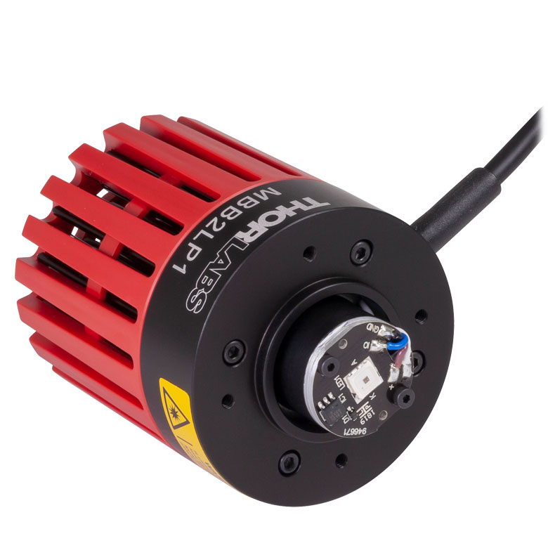 |
740 mW / 1090 mWi | N/A | 13.5 µW/mm2 d,i | 1000 mAi | 4.8 Vi | 120° i | |||
- Click on the info icon ( ) for complete specifications and LED spectrum.
- Due to variations in the manufacturing process and operating parameters such as temperature and current, the actual spectral output of any given LED will vary. Output plots and nominal wavelength specs are only intended to be used as a guideline.
- Click for LED Product Photo
- When Driven at the Max Current
- Irradiance is measured at a distance of 200 mm from the LED.
- Drivers for which max voltage and max current are greater than or equal to the forward voltage and max current of the LED, respectively. See the LED Drivers tab for the specifications of each driver.
- The LED may not turn off completely when modulated at frequencies above 1 kHz with a duty cycle of 50%, as the broadband emission is produced by optically stimulating emission from phosphor. For modulation at frequencies above 1 kHz, the duty cycle may be reduced. For example, 10 kHz modulation is attainable with a duty cycle of 5%.
- This is a four-channel driver and requires the DC4100-HUB connector hub to drive mounted LEDs.
- Measured at 25 °C
 or Ø2in (Ø50 mm) Optics")
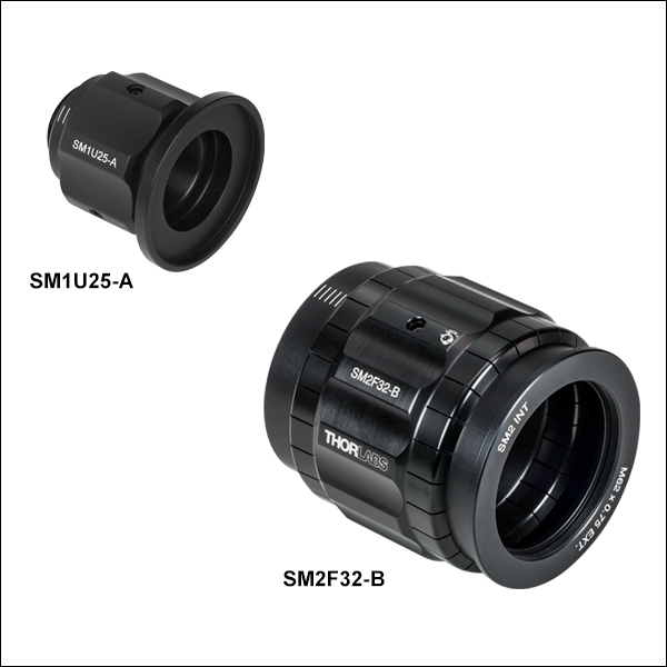 Zoom
Zoom| Table G10.2 LED Quick Links |
|---|
| Mounted LEDs |
| Deep UV (233 - 340 nm) |
| UV (365 - 405 nm) |
| Cold Visible (415 - 565 nm) |
| Warm Visible (590 - 730 nm) |
| IR (780 - 1900 nm) |
| Mid-IR (3400 - 5200 nm) |
| Purple (455 nm / 640 nm) |
| White (400 - 700 nm) |
| Broadband Mounted LEDs |
| LED Collimationa |
| Adjustable Collimation Adapters |
| Microscope Collimation Adapters |
| LED Mating Connector |
| LED Drivers |
- We offer suggestions for how to collimate most of our LEDs. Click on the info icons ( ) for details.
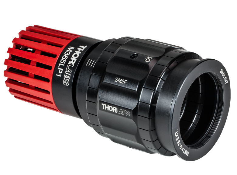
Click to Enlarge
Figure G10.1 SM2F Adapter Installed on a M365LP1 Mounted LED
- Integrate a Ø1" (Ø25 mm) or Ø2" (Ø50 mm) Collimation Optic with Thorlabs' Mounted LEDs
- Adjust and Set Lens Position via Rotating Ring with Locking Setscrew
- Available with or without AR-Coated Lens (See Table G10.3 for Details)
- Compatible with Thorlabs' SM2-Threaded Microscope Port Adapters
These adapters allow Ø1" (Ø25 mm) or Ø2" (Ø50 mm) collimation optics to be integrated with the mounted LEDs sold above. The adapters can translate a Ø1" or Ø2" lens by up to 11 mm or 20 mm, respectively. They are offered in versions without a collimation optic or with a removable AR-coated aspheric condenser lens for 350 - 700 nm or 650 - 1050 nm. All of these adapters attach to the LED housing via external SM1 threads, allowing them to be used with both the Ø30.5 mm and Ø57.0 mm housings.
The collimation lens is mounted in an inner carriage that provides non-telescoping, rotating translation along the Z-axis by turning the knurled adjustment ring (engraved with the item # SM2F in Figure G10.1) and is locked into position by turning the locking screw on the side of the adjustment ring with a 2 mm (5/64") hex key. Lines, spaced 2 mm apart, are engraved on the housing as a rough guide for how far the carriage has been translated. These collimation adapters use an extra-thick SM1-threaded or SM2-threaded retaining ring designed for holding aspheric condenser lenses. The retaining rings can be tightened or loosened using either an SPW602 (Ø1" versions) or SPW604 (Ø2" versions) spanner wrench.
The threading on the input and output apertures remain fixed during translation, allowing these adapters to be mounted between fixed lens tubes. These apertures are threaded for compatibility with various components; please see Table G10.3 for details.
Inserting or Removing Optics
To insert or remove an optic in these collimation adapters, use the adjustment ring to translate the inner carriage to the output end of the housing. Remove the included retaining ring using the spanner wrench. If there is a lens installed already, remove it from the carriage. Insert another Ø1" (Ø25 mm) or Ø2" (Ø50 mm) optic into the carriage, and use the retaining ring to secure it.
Using a lens with a substrate or AR coating that does not transmit the wavelength of your LED is not recommended. Deep UV LEDs (wavelengths ≤ 340 nm) require a lens fabricated from UV Fused Silica, since many standard varieties of glass do not transmit below 350 nm. IR LEDs that emit at wavelengths ≥ 1050 nm can be collimated using an uncoated condenser lens, such as the Ø50 mm ACL50832U which has a wavelength range of 380 - 2100 nm.
| Table G10.3 Specifications | |||||||||
|---|---|---|---|---|---|---|---|---|---|
| Item # | Compatible Optic |
Lens Travel Range |
Input Threading | Output Threading | Included Lens |
AR Coating Range |
Lens Focal Length |
Operating Temperature |
Diagram |
| SM1Ua | Ø1" (Ø25 mm) | 11 mm (0.43") | External SM1 (1.035"-40) | Internal SM2 (2.035"-40)b | N/A | N/A | N/A | 15 - 60 °C (Non-Condensing) |
|
| SM1U25-A | ACL2520U-A | 350 - 700 nm | 20.1 mm | ||||||
| SM1U25-B | ACL2520U-B | 650 - 1050 nm | 20.1 mm | ||||||
| SM2Fa | Ø2" (Ø50 mm) | 20 mm (0.79") | External SM1 (1.035"-40)c | Internal SM2 (2.035"-40)d | N/A | N/A | N/A | ||
| SM2F32-A | ACL50832U-A | 350 - 700 nm | 32.0 mm | ||||||
| SM2F32-B | ACL50832U-B | 650 - 1050 nm | 32.0 mm | ||||||
| Table G11.2 LED Quick Links |
|---|
| Mounted LEDs |
| Deep UV (233 - 340 nm) |
| UV (365 - 405 nm) |
| Cold Visible (415 - 565 nm) |
| Warm Visible (590 - 730 nm) |
| IR (780 - 1900 nm) |
| Mid-IR (3400 - 5200 nm) |
| Purple (455 nm / 640 nm) |
| White (400 - 700 nm) |
| Broadband Mounted LEDs |
| LED Collimationa |
| Adjustable Collimation Adapters |
| Microscope Collimation Adapters |
| LED Mating Connector |
| LED Drivers |
- We offer suggestions for how to collimate most of our LEDs. Click on the info icons ( ) for details.
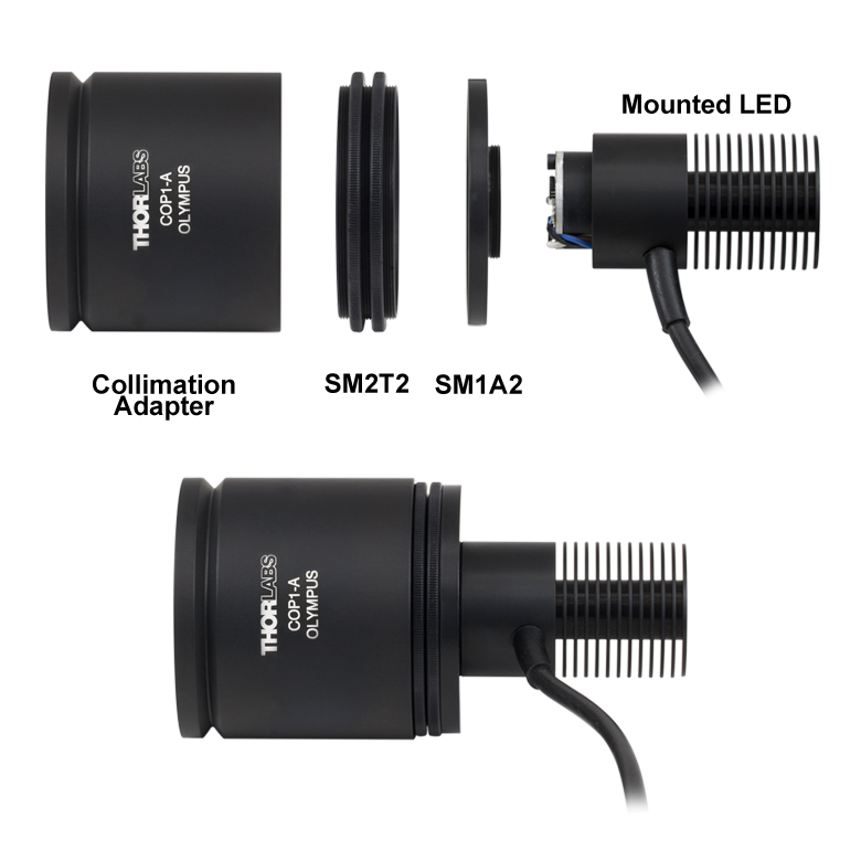
Click for Details
Figure G11.1 Installation of a collimation adapter to a mounted LED using the SM2T2 and SM1A2 thread adapters. The same setup can be used to attach the collimation adapter to the LEDs sold above that use a Ø57.0 mm housing.
- AR-Coated Aspheric Lens with Low f/# (Approximately 0.8)
- Compatible with Select Leica, Nikon, Olympus, or Zeiss Microscopes
- Easily Adjust Beam Collimation / Focus
- Requires SM2T2 Coupler and SM1A2 Adapter (Each Sold Separately) when Used with the LEDs Above
Thorlabs offers collimation adapters with Ø50 mm AR-coated aspheric condenser lenses (EFL: 40 mm) for collimating the output from the mounted LEDs sold above. Two AR coating ranges (350 - 700 nm and 650 - 1050 nm) and four different collimator housings are available. Each housing is designed with a dovetail or bayonet mount to mate to the illumination port on selected Olympus*, Leica, Nikon, or Zeiss microscopes. Compatible microscopes are listed in Table G11.3.
Using an adapter with a substrate or AR coating that does not transmit the wavelength of your LED is not recommended. Deep UV LEDs require a lens fabricated from UV Fused Silica, since many standard varieties of glass do not transmit below 350 nm. IR LEDs that emit beyond 1050 nm can be collimated using an uncoated condenser lens; the ACL5040U is an uncoated version of the Ø50 mm lenses used in the collimation packages here that has a wavelength range of 380 - 2100 nm. See the Collimation Adapter tab in the info icons for additional collimation options that may be used with our LEDs that emit over the range 365 - 1650 nm.
The LED sources described above can be fitted to the collimators by using an SM2T2 Coupler and SM1A2 Adapter (not included) as shown in Figure G11.1. This assembly can be easily adapted to different LED sources by unscrewing the LED housing.
*Please note that due to the optical design of the transmitted lamphouse port of the BX and IX microscopes, it may be necessary to purchase a separate adapter, which is available from Olympus.
| Table G11.3 Collimation Adapter Selection Guide | |||||||
|---|---|---|---|---|---|---|---|
| Compatible Microscopes | Olympus BX & IXa | Leica DMI | Zeiss Axioskop & Examinerb | Nikon Eclipse Ti | |||
| AR Coating Range of Condenser Lens |
Lens Focal Length |
Lens Item # | 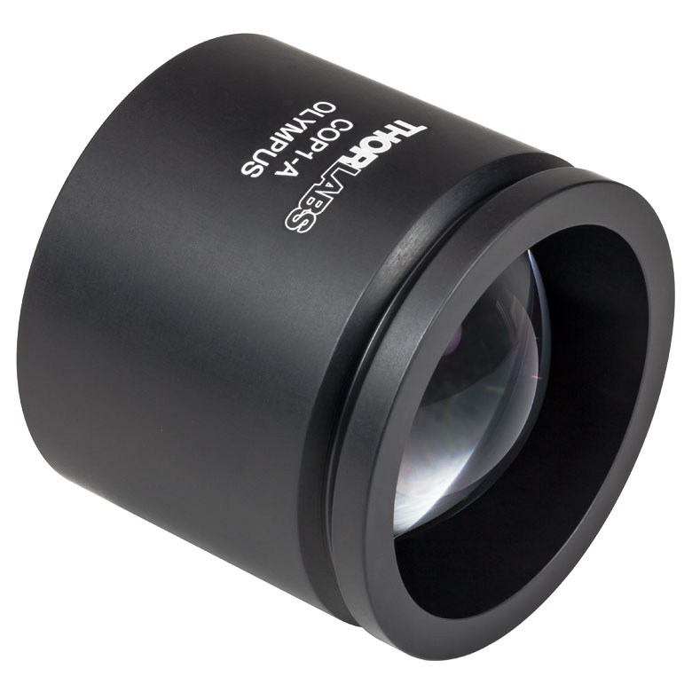 Click to Enlarge |
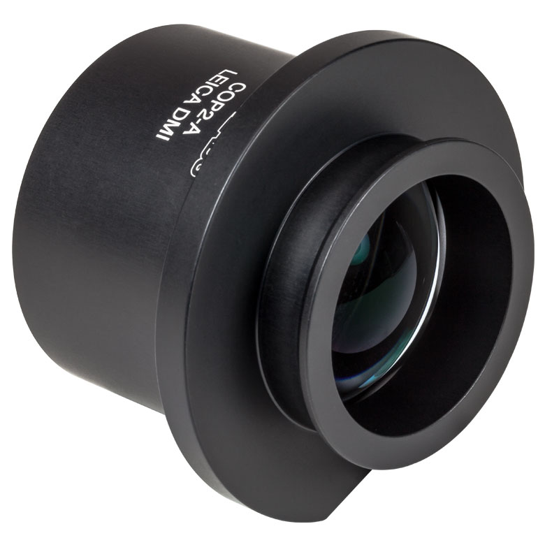 Click to Enlarge |
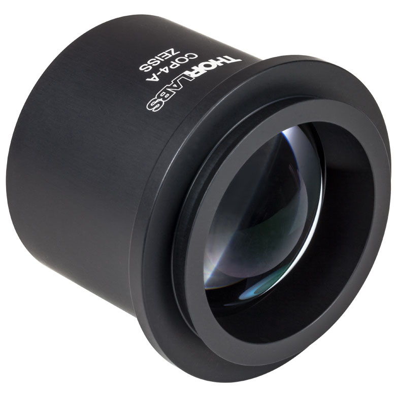 Click to Enlarge |
 Click to Enlarge |
|
| 350 - 700 nm | 40.0 mm | ACL5040U-A | COP1-A | COP2-A | COP4-A | COP5-A | |
| 650 - 1050 nm | 40.0 mm | ACL5040U-B | COP1-B | COP2-B | COP4-B | COP5-B | |

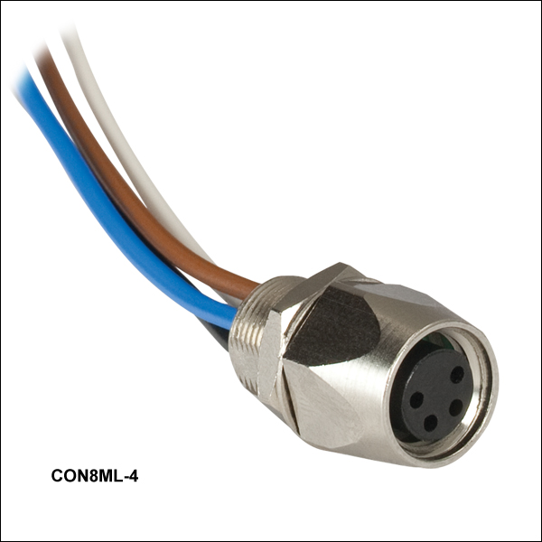 Zoom
Zoom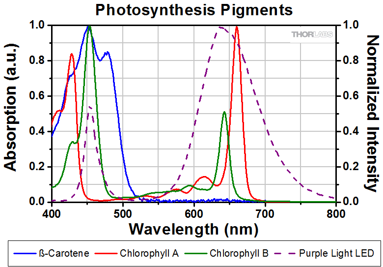
- Female 4-Pin Pico (M8) Receptacle
- M8 x 1 Thread for Connection to Mounted LED Power Cable
- M8 x 0.5 Panel-Mount Thread for Custom Housings
- 0.5 m Long, 24 AWG Wires
- IP 67 and NEMA 6P Rated
The CON8ML-4 connector can be used to mate mounted LEDs featured on this page to user-supplied power supplies. We also offer a male 4-Pin M8 connector cable (item # CAB-LEDD1).
| Pin | Color | Specification | 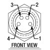 |
|---|---|---|---|
| 1 | Brown | LED Anode | |
| 2 | White | LED Cathode | |
| 3 | Black | EEPROM GND | |
| 4 | Blue | EEPROM IO |

Figure 363A CON8ML-4 Shown Connected to the 4-Pin M8 Plug of Mounted LED