 Products Home / Custom Solutions & Manufacturing Capabilities / Scientific Cameras: OEM and Manufacturing Capabilities
Scientific Cameras: OEM and Manufacturing Capabilities

Please Wait

Sam Tesfai
General Manager,
Thorlabs Imaging Systems
Feedback?
Questions?
Need a Quote?
Click to Enlarge
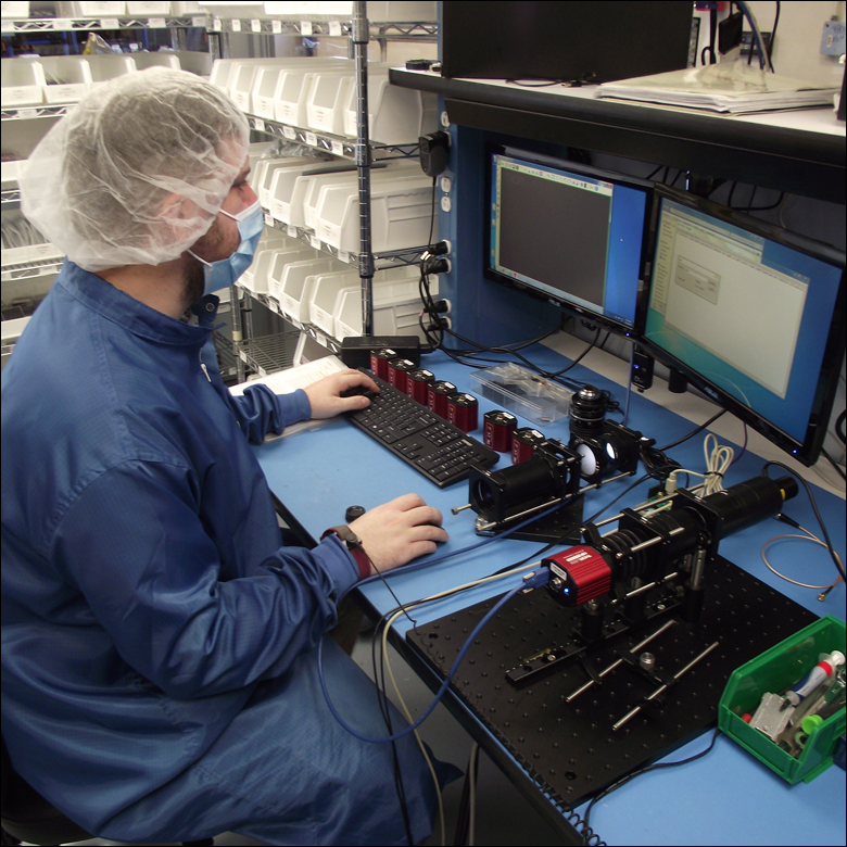
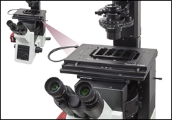
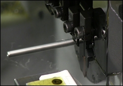
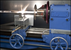
Figure 1.2 Every scientific camera undergoes extensive testing to ensure high performance.
Click to Enlarge
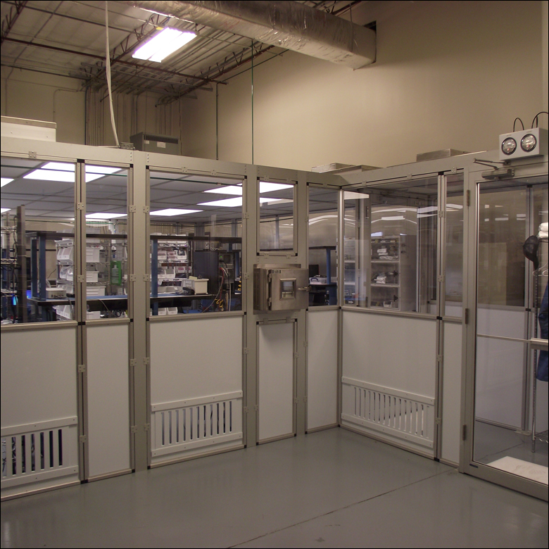
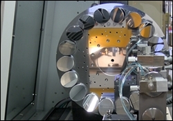
Figure 1.1 All of our scientific cameras are assembled and inspected in a class 10,000 cleanroom.
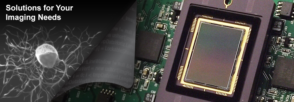
Thorlabs Imaging Systems
The Thorlabs Imaging Systems in Sterling, Virginia works in a multidisciplinary environment to develop challenging circuit designs, innovative optical and mechanical solutions, firmware, and host side software in a camera platform that can be used with a variety of imagers. We offer a wide selection of sCMOS and CMOS cameras, which have been deployed in numerous applications (see the Selection Guide and Camera Applications tabs). Our unique and diverse skill base gives us the ability to customize low-noise, high-performance scientific cameras and interface devices that fit your needs. For more details about all of our products and services, please see the Thorlabs Expertise tab.
Cameras Manufactured to Stringent Quality Controls
We understand that reliability and optical cleanliness are critical requirements for quality scientific cameras, which is why all Thorlabs cameras are assembled and inspected in a class 10,000 cleanroom; see Figures 1.1 and 1.2. The optics undergo a full inspection and cleaning to ensure they meet quality standards. The cameras are assembled and extensively tested to validate proper electronic operation. We capture a range of final images with every camera to ensure excellent performance. All test data is traceable back to the individual camera serial number. This ensures that each camera installed in an OEM system, research lab, or production environment is delivered to the highest traceable standards.
Request OEM or Custom Cameras in Two Easy Steps
Thorlabs Imaging Systems makes it easy to get the camera that you need for a specific application. Along with our large selection of standard scientific cameras, we also offer customized and OEM products. These include high-performance cameras, board-level cameras, custom camera housings, and software. A full-featured and well-documented API, included with our cameras, makes it convenient to develop fully customized applications in an efficient manner, while also providing the ability to migrate through our product line without having to rewrite an application. If you have special requirements, a custom application, or general questions about our capabilities, please contact us; we will work with you to get the product you need for your application.
Customizing a scientific camera can be done from scratch or by using one of our existing standard cameras as a starting point. All of our cameras can be designed for low-light and/or high-speed imaging systems and tailored to meet stringent size, environmental, and packaging requirements. Thorlabs Imaging Systems simplifies this process by using the two steps below. Small changes made to our existing stock, such as private labeling, timing circuitry within the electronics, or mechanical changes, can be quickly and easily done using these steps. When designing a custom camera from scratch, we will help walk you through everything detailed below. The process is simplified to help you match the camera to the specific needs of your application. We also offer Kanban options for OEM customers.
Step 1: Analyze your Custom or OEM RequirementsImaging Specifications:
System Requirements:
Application Space:
|
|||
Step 2: Work with Thorlabs Imaging Systems to Configure a SolutionImager Options:
I/O Options:
Camera Body Options:
Electronics Modifications:
Supply Chain:
Software:
|

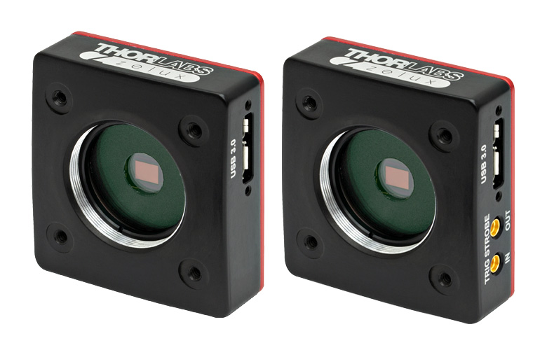
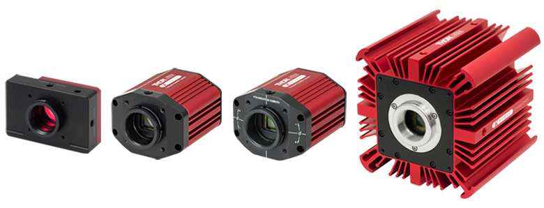
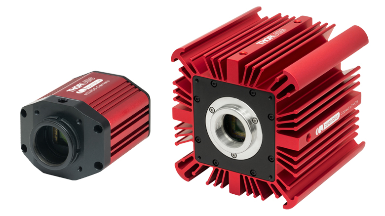
Thorlabs offers three families of scientific cameras: Zelux®, Kiralux®, and Quantalux®. Zelux cameras are designed for general-purpose imaging and provide high imaging performance while maintaining a small footprint. Kiralux cameras have CMOS sensors in monochrome, color, NIR-enhanced, or polarization-sensitive versions and are available in low-profile, passively cooled housings; compact, passively cooled housings; or hermetically sealed, TE-cooled housings. The polarization-sensitive Kiralux camera incorporates an integrated micropolarizer array that, when used with our ThorImage®CAM software package, captures images that illustrate degree of linear polarization, azimuth, and intensity at the pixel level. Our Quantalux monochrome sCMOS cameras feature high dynamic range combined with extremely low read noise for low-light applications. They are available in either a compact, passively cooled housing or a hermetically sealed, TE-cooled housing. Table 134A provide a summary of our camera offerings.
| Table 134A Compact Scientific Cameras | |||||||
|---|---|---|---|---|---|---|---|
| Camera Type | Zelux® CMOS | Kiralux® CMOS | Quantalux® sCMOS | ||||
| 1.6 MP | 1.3 MP | 2.3 MP | 5 MP | 8.9 MP | 12.3 MP | 2.1 MP | |
| Item # | Monochrome: CS165MUa Color: CS165CUa |
Mono.: CS135MU Color: CS135CU NIR-Enhanced Mono.: CS135MUN |
Mono.: CS235MU Color: CS235CU |
Mono., Passive Cooling: CS505MU1 CS505MU Mono., Active Cooling: CC505MU Color: CS505CU1 CS505CU Polarization: CS505MUP1 |
Mono., Passive Cooling: CS895MU Mono., Active Cooling: CC895MU Color: CS895CU |
Mono., Passive Cooling: CS126MU LP126MU(/M) Mono., Active Cooling: CC126MU Color, Passive Cooling: CS126CU LP126CU(/M) |
Monochrome, Passive Cooling: CS2100M-USB Active Cooling: CC215MU |
| Product Photos (Click to Enlarge) |
 |
 |
 |
||||
| Electronic Shutter | Global Shutter | Global Shutter | Rolling Shutterb | ||||
| Sensor Type | CMOS | CMOS | sCMOS | ||||
| Number of Pixels |
1440 x 1080 (H x V) | 1280 x 1024 (H x V) | 1920 x 1200 (H x V) | 2448 x 2048 (H x V) | 4096 x 2160 (H x V) |
4096 x 3000 (H x V) |
1920 x 1080 (H x V) |
| Pixel Size | 3.45 µm x 3.45 µm | 4.8 µm x 4.8 µm | 5.86 µm x 5.86 µm | 3.45 µm x 3.45 µm | 5.04 µm x 5.04 µm | ||
| Optical Format |
1/2.9" (6.2 mm Diag.) |
1/2" (7.76 mm Diag.) |
1/1.2" (13.4 mm Diag.) |
2/3" (11 mm Diag.) |
1" (16 mm Diag.) |
1.1" (17.5 mm Diag.) |
2/3" (11 mm Diag.) |
| Peak Quantum Efficiency (Click for Plot) |
Monochrome: 69% at 575 nm Color: Click for Plot |
Monochrome: 59% at 550 nm Color: Click for Plot NIR: 60% at 600 nm |
Monochrome: 78% at 500 nm Color: Click for Plot |
Monochrome & Polarization: 72% (525 to 580 nm) Color: Click for Plot |
Monochrome: 72% (525 to 580 nm) Color: Click for Plot |
Monochrome: 72% (525 to 580 nm) Color: Click for Plot |
Monochrome: 61% (at 600 nm) |
| Max Frame Rate (Full Sensor) |
34.8 fps | 165.5 fps | 39.7 fps | 35 fps (CS505xx1, CC505MU, CS505MUP1), 53.2 fps (CS505xx) |
20.8 fps (CC895MU), 30.15 fps (CS895xx) |
15.1 fps (CC126MU), 21.7 fps (CS126xx and LP126xx(/M)) |
50 fps |
| Read Noise | <4.0 e- RMS | <7.0 e- RMS | <7.0 e- RMS | <2.5 e- RMS | <1 e- Median RMS; <1.5 e- RMS | ||
| Digital Output |
10 Bit (Max) | 10 Bit (Max) | 12 Bit (Max) | 16 Bit (Max) | |||
| PC Interface | USB 3.0 | ||||||
| Available Fanless Cooling |
N/A | N/A | N/A | 15 °C to 20 °C Below Ambient Temperature (CCxxxMU Cameras Only) | |||
| Housing Size (Click for Details) |
0.59" x 1.72" x 1.86" (15.0 x 43.7 x 47.2 mm3) |
Passively Cooled CMOS Camera TE-Cooled CMOS Camera Passively Cooled Low-Profile CMOS Camera |
Passively Cooled sCMOS Camera TE-Cooled sCMOS Camera |
||||
| Typical Applications |
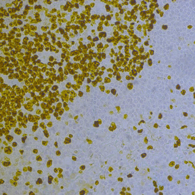
Mono. & Color: Brightfield Microscopy, General Purpose Imaging, Machine Vision, Material Sciences, Materials Inspection, Monitoring, Transmitted Light Spectroscopy, UAV, Drone, & Handheld Imaging Mono. Only: Multispectral Imaging, Semiconductor Inspection Color Only: Histopathology |
Mono., Color, & NIR: Brightfield Microscopy, Ca++ Ion Imaging, Electrophysiology/Brain Slice Imaging, Flow Cytometry, Fluorescence Microscopy, General Purpose Imaging, Immunohistochemistry (IHC), Laser Speckle Imaging, Machine Vision, Material Sciences, Materials Inspection, Vascular Imaging, Monitoring, Particle Tracking, Transmitted Light Spectroscopy, Vascular Imaging, VIS/NIR Imaging Mono. Only: Multispectral Imaging Semiconductor Inspection Color Only: Histopathology NIR Only: Ophthalmology/Retinal Imaging |
Mono. & Color: Autofluorescence, Brightfield Microscopy, Electrophysiology/Brain Slice Imaging, Fluorescence Microscopy, Immunohistochemistry (IHC), Machine Vision, Material Sciences, Materials Inspection, Monitoring, Quantitative Phase-Contrast Microscopy, Transmitted Light Microscopy Mono. Only: Multispectral Imaging Semiconductor Inspection Color Only: Histopathology |
Mono. & Color: Autofluorescence, Brightfield Microscopy, Electrophysiology/Brain Slice Imaging, Fluorescence Microscopy, Immunohistochemistry (IHC), Machine Vision, Material Sciences, Materials Inspection, Monitoring, Quantitative Phase-Contrast Microscopy, Transmitted Light Microscopy Mono. Only: Multispectral Imaging, Semiconductor Inspection Color Only: Histopathology Polarization Only: Inspection, Surface Reflection Reduction, Transparent Material Detection |
Mono. & Color: Autofluorescence, Brightfield Microscopy, Electrophysiology/Brain Slice Imaging, Fluorescence Microscopy, Immunohistochemistry (IHC), Machine Vision, Material Science, Materials Inspection, Monitoring, Quantitative Phase-Contrast Microscopy, Transmitted Light Microscopy Mono. Only: Multispectral Imaging, Ophthalmology/Retinal Imaging, Semiconductor Inspection Color Only: Histopathology LP126xx(/M), CS126xx, and CC126MU Only: Whole-Slide Microscopy |
Passive & Active Cooling: Autofluorescence, Brightfield Microscopy, Fluorescence Microscopy, Immunohistochemistry (IHC), Material Sciences, Materials Inspection, Monitoring, Quantitative Phase-Contrast Microscopy, Quantum Dots, Semiconductor Inspection, Transmitted Light Microscopy, Whole-Slide Microscopy Active Cooling Only: Electrophysiology/Brain Slice Imaging, Multispectral Imaging |
|
Applications
Applications Overview
Thorlabs' Scientific-Grade Cameras are ideal for a variety of applications. The photo gallery in Table 9A contains images acquired with our 1.4 MP CCD (previous generation), 4 MP CCD (previous generation), 8 MP CCD (previous generation), and fast frame rate CCD (previous generation) cameras.
To download some of these images as high-resolution, 16-bit TIFF files, please click here. It may be necessary to use an alternative image viewer to view the 16-bit files. We recommend ImageJ, which is a free download.
| Table 9A Standard, Customized, or OEM Cameras and Software for a Range of Applications (Click Each Image for Details) | |||||
|---|---|---|---|---|---|
 |
 |
 |
 |
 |
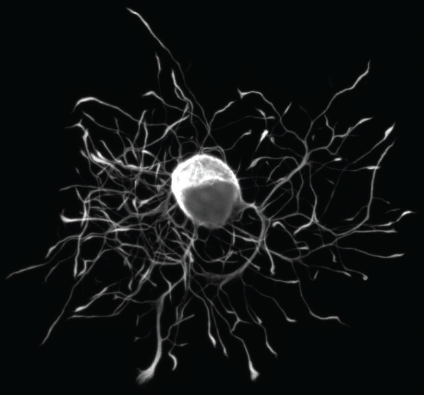 |
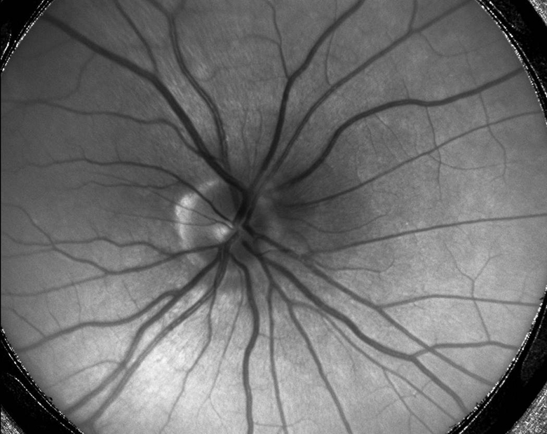
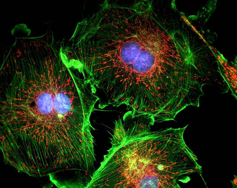
| Intracellular Dynamics | Brightfield Microscopy | Ophthalmology (NIR) | Fluorescence Microscopy | Multispectral Imaging | Neuroscience |
| Thorlabs' Scientific Cameras Recommended for Each Application Above | |||||
| Quantalux® 2.1 MP sCMOS | Kiralux® 1.3 MP CMOS Zelux™ 1.6 MP CMOS Kiralux 2.3 MP CMOS Kiralux 5 MP CMOS Kiralux 8.9 MP CMOS Kiralux 12.3 MP CMOS |
Kiralux 1.3 MP CMOS Kiralux 2.3 MP CMOS Kiralux 5 MP CMOS Kiralux 8.9 MP CMOS Kiralux 12.3 MP CMOS |
Quantalux 2.1 MP sCMOS Kiralux 2.3 MP CMOS Kiralux 5 MP CMOS Kiralux 8.9 MP CMOS Kiralux 12.3 MP CMOS |
Quantalux 2.1 MP sCMOS Kiralux 2.3 MP CMOS Kiralux 5 MP CMOS |
Quantalux 2.1 MP sCMOS Kiralux 2.3 MP CMOS Kiralux 5 MP CMOS Kiralux 8.9 MP CMOS Kiralux 12.3 MP CMOS |
Multispectral Imaging
Video 9B Multispectral Image Acquisition
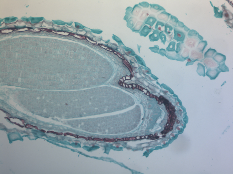
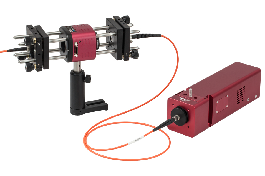
Video 9B is an example of a multispectral image acquisition using a liquid crystal tunable filter (LCTF) in front of a monochrome camera. With a sample slide exposed to broadband light, the LCTF passes narrow bands of light that are transmitted from the sample. The monochromatic images are captured using a monochrome scientific camera, resulting in a datacube - a stack of spectrally separated two-dimensional images which can be used for quantitative analysis, such as finding ratios or thresholds and spectral unmixing.
In the example shown, a mature capsella bursa-pastoris embryo, also known as Shepherd's-Purse, is rapidly scanned across the 420 nm - 730 nm wavelength range using Thorlabs' previous-generation KURIOS-WB1 Liquid Crystal Tunable Filter. The images are captured using our legacy 1501M-GE Scientific Camera, which is connected, with the liquid crystal filter, to a Cerna® Series Microscope. The overall system magnification is 10X. The final stacked/recovered image is shown in Figure 9C.
Click to Enlarge
Figure 9C Final Stacked/Recovered Image
Thrombosis Studies
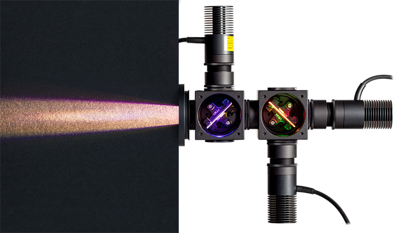
Thrombosis is the formation of a blood clot within a blood vessel that will impede the flow of blood in the circulatory system. The Videos 9D and 9E are from experimental studies on the large-vessel thrombosis in Mice performed by Dr. Brian Cooley at the Medical College of Wisconsin. Three lasers (532 nm, 594 nm, and 650 nm) were expanded and then focused on a microsurgical field of an exposed surgical site in an anesthetized mouse. A custom, previous-generation 1.4 Megapixel Camera with integrated filter wheel was attached to a Leica Microscope to capture the low-light fluorescence emitted from the surgical site. See Videos 9D and 9E with their associated descriptions for further information.
Arterial Thrombosis
Video 9D In this video, a gentle 30-second electrolytic injury is generated on the surface of a carotid artery in an atherogenic mouse (ApoE-null on a high-fat, “Western” diet), using a 100-micron-diameter iron wire (creating a free-radical injury). The site (arrowhead) and the vessel are imaged by time-lapse fluorescence-capture, low-light camera over 60 minutes (timer is shown in upper left corner - hours:minutes:seconds). Platelets were labeled with a green fluorophore (rhodamine 6G) and anti-fibrin antibodies with a red fluorophore (Alexa-647) and injected prior to electrolytic injury to identify the development of platelets and fibrin in the developing thrombus. Flow is from left to right; the artery is approximately 500 microns in diameter (bar at lower right, 350 microns).
Venous Thrombosis
Video 9E In this video, a gentle 30-second electrolytic injury is generated on the surface of a murine femoral vein, using a 100-micron-diameter iron wire (creating a free-radical injury). The site (arrowhead) and the vessel are imaged by time-lapse fluorescence-capture, low-light camera over 60 minutes (timer is shown in upper left corner – hours:minutes:seconds). Platelets were labeled with a green fluorophore (rhodamine 6G) and anti-fibrin antibodies with a red fluorophore (Alexa-647) and injected prior to electrolytic injury to identify the development of platelets and fibrin in the developing thrombus. Flow is from left to right; the vein is approximately 500 microns in diameter (bar at lower right, 350 microns).
Reference: Cooley BC. In vivo fluorescence imaging of large-vessel thrombosis in mice. Arterioscler Thromb Vasc Biol 31, 1351-1356, 2011. All animal studies were done under protocols approved by the Medical College of Wisconsin Institutional Animal Care and Use Committee.
Click to Enlarge
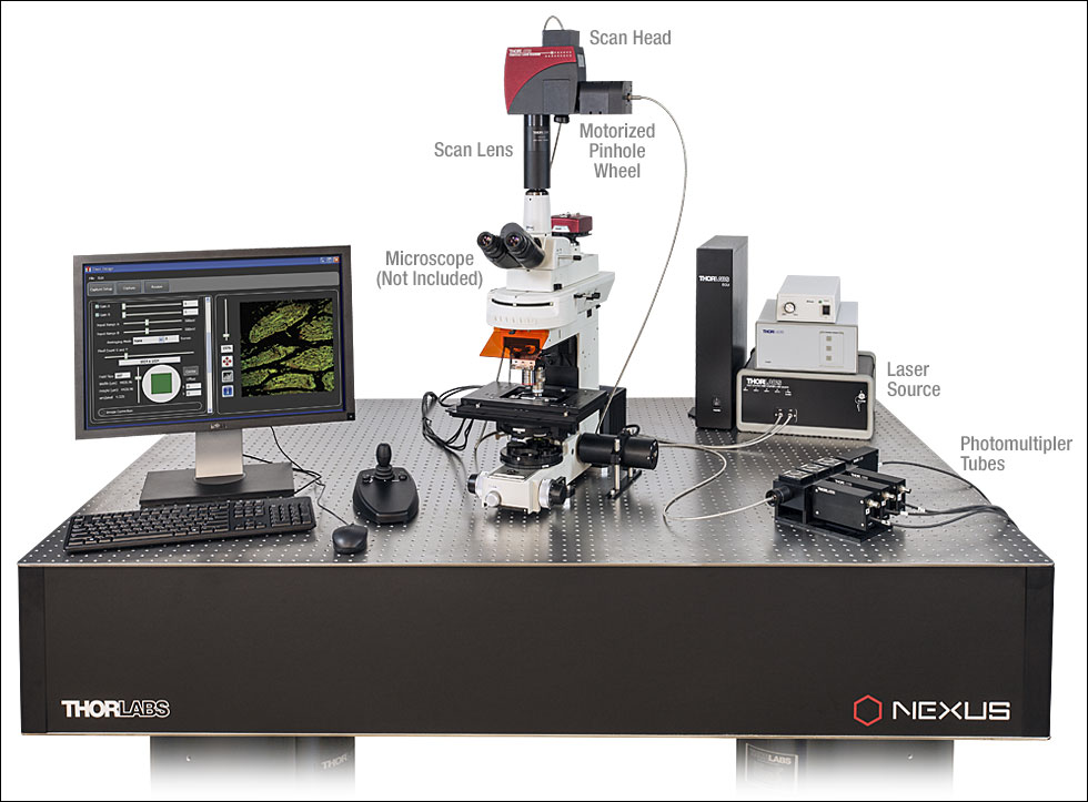
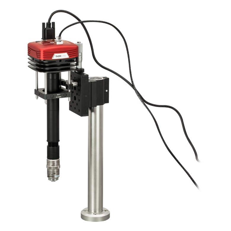
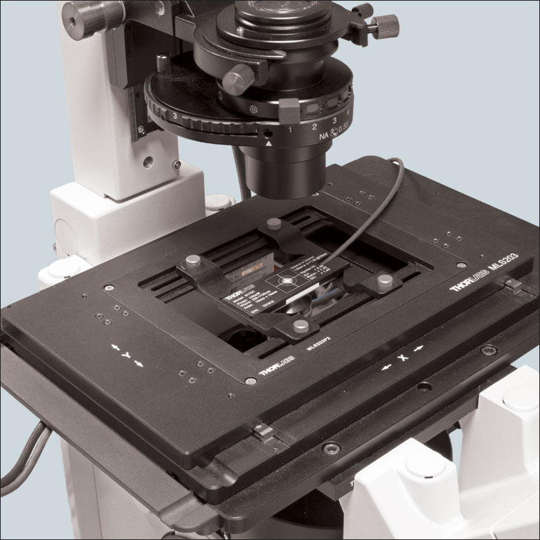
Figure 9F Example Setup for Simultaneous NIR/DIC and Fluorescence Imaging
Live Dual-Channel Imaging
Many life science imaging experiments require a cell sample to be tested and imaged under varying experimental conditions over a significant period of time. One common technique to monitor complex cell dynamics in these experiments uses fluorophores to identify relevant cells within a sample, while simultaneously using NIR or differential interference contrast (DIC) microscopy to probe individual cells. Registering the two microscopy images to monitor changing conditions can be a difficult and frustrating task.
Live overlay imaging allows both images comprising the composite to be updated in real-time versus other methods that use a static image with a real-time overlay. Overlays with static images require frequent updates of the static image due to drift in the system or sample, or due to repositioning of the sample. Live overlay imaging removes that dependency by providing live streaming in both channels.
Using the ThorCam overlay plug-in with the two-way camera microscope mount, users can generate real-time two-channel composite images with live streaming updates from both camera channels, eliminating the need for frequent updates of a static overlay image. This live imaging method is ideal for applications such as calcium ratio imaging and electrophysiology.
Example Images
Simultaneous Fluorescence and DIC Imaging
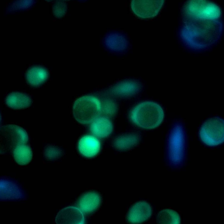
The image sequence shown in Figures 9G, 9H, and 9J shows mouse kidney cells imaged using a dichroic filter to separate the fluorescence and DIC signals into different cameras. These images are then combined into a two-channel composite live image with false color fluorescence by the ThorCam overlay plug-in.
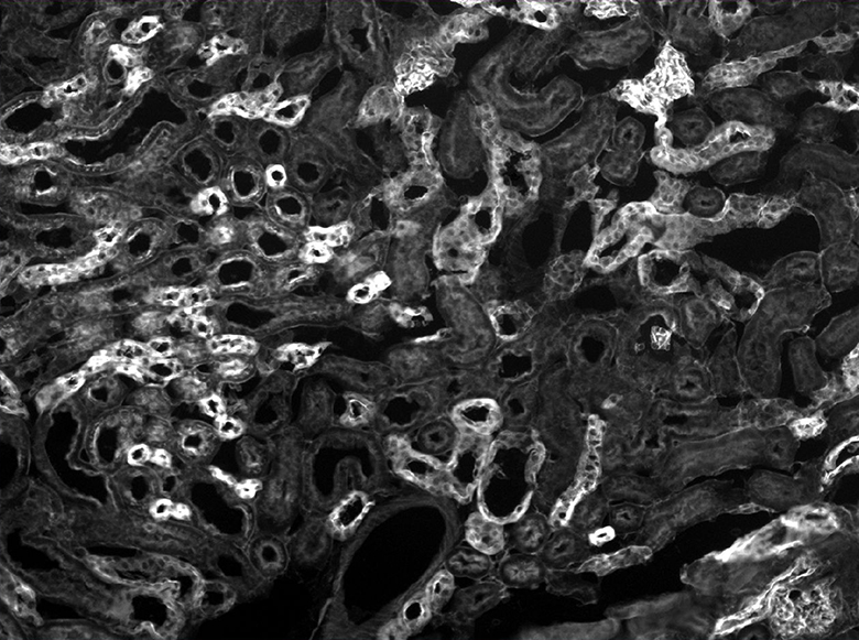
Click to Enlarge
Figure 9G Fluorescence Image
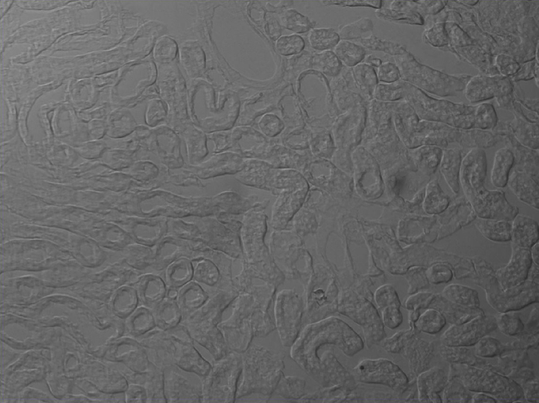
Click to Enlarge
Figure 9H DIC Image
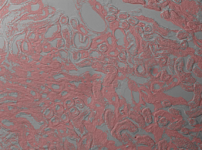
Click to Enlarge
Figure 9J 2-Channel Composite Live Image
Click to Enlarge
Figure 9K In this image, the pipette is visible in the DIC image as two lines near the center of the frame.
Microaspiration Using a Micropipette
Figure 9K shows a live, simultaneous overlay of fluorescence and DIC images. The experiment consists of a microaspiration technique using a micropipette to isolate a single neuron that expresses GFP. This neuron can then be used for PCR. This image was taken with our previous-generation 1.4 Megapixel Cameras and a two-camera mount and shows the live overlay of fluorescence and DIC from the ThorCam plug-in. Image courtesy of Ain Chung, in collaboration with Dr. Andre Fenton at NYU and Dr. Juan Marcos Alarcon at The Robert F. Furchgott Center for Neural and Behavioral Science, Department of Pathology, SUNY Downstate Medical Center.

Click to Enlarge
Figure 9L NIR Dodt and Fluorescence Imaging of a 50 µm Brain Section of a
Simultaneous NIR Dodt Contrast and Epi Fluorescence Imaging
Figure 9L shows a live, simultaneous overlay of fluorescence and near-infrared Dodt contrast images of a 50 µm brain section from a CX3CR1-GFP mouse, which has been immunostained for PECAM-1 with Alexa-687 to highlight vasculature. The Dodt contrast uses a quarter annulus and a diffuser to create a gradient of light across the sample that can reveal the structure of thick samples. The image was taken with our Scientific Cameras and a two-camera mount. Sample courtesy of Dr. Andrew Chojnacki, Department of Physiology and Pharmacology, Live Cell Imaging Facility, Snyder Institute for Chronic Diseases, University of Calgary.
Our Expertise in the Photonics and Imaging Industry
Thorlabs is a leading photonics company that develops and manufactures a broad portfolio of technologies ranging from optical components to advanced imaging systems. We develop and manufacture most of our components at our extensive high-tech fabrication facilities. The facilities include manufacturing capabilities for motion control products, optoelectronics, semiconductors, optical fiber, optomechanics, optics, and optical coatings. Components that directly support our scientific camera line are filters and filter wheels, objective and scan lenses, zoom lenses, mounting adapters, LEDs, microscopy components and stages, and rigid cage systems.
Competencies
- Extensive Knowledge of Photonics Technology
- Unique Skillset to Design and Manufacture Low-Noise, High-Performance Scientific Cameras, Interfaces, and Software
- Vertically Integrated Manufacturing Facilities
- Variety of Existing Products from Across Different Fields
- Close Contact with Research Labs Around the World
Experienced Team
- Interdisciplinary Teams Comprised of Scientists, Engineers, and Technicians
- Extensive Portfolio of Products Developed and Manufactured by Thorlabs Ranging From Mechanical Components to Imaging Systems
- Many Optical Systems Successfuly Designed, Manufactured, and Deployed into the Field


| Posted Comments: | |
| No Comments Posted |