 Products Home
Motion Control Capabilities

Please Wait
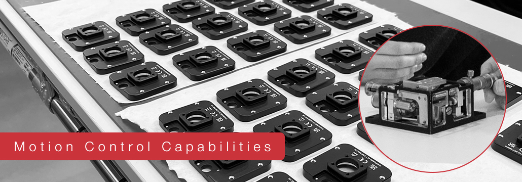
Motion Control Capabilities
Our team is dedicated to creating high-quality motion control products.
Based in Ely, UK, Thorlabs, LTD. is home to the machinery, design resources, and lean manufacturing processes necessary to develop both catalog and custom motion control solutions. Our team develops mechanics that are machined to precise tolerances, electronics that are customized for specific applications, and software that has been stress-tested in-house and proven in customer deployments. Please explore this webpage to learn more.
Customization Options
- Custom Solutions for Photonics, Biological Sciences, and Industrial OEMs
- SolidWorks®* Software Modeling, Finite Element Analysis, and 3D Printing Reduce Lead Time of Custom Designs
- In-House R&D Machining Capabilities: 3- and 5-Axis CNC Machining, Horizontal CNC Machining (Lathe), Wire Erosion Machining (EDM), Sheet Metal Bending, and Laser Cutting
- Modifications to Standard Products Add Functionality and Mounting Flexibility
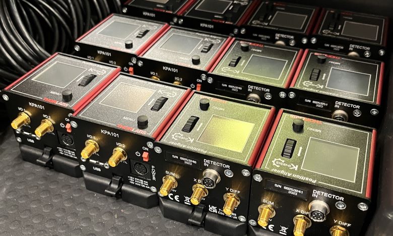
- Customized Electronics and Controller Cards
- Unanodized Components, Ventilation Holes, Specialized Grease, and Other Materials for Use in Vacuum Applications Down to 10-6 Torr
- Embedded Electronics, Modified and Custom Hole Patterns, Adapters for Different Mounting Configurations, and More
Quality and Engineering Standards
- ISO 9001:2015 - Quality Management System
- ANSI/ASQ Z 1.4-2003 - Sampling Standards for Quality Control
- BS EN 61010-1:2010+A1:2019 - Design Safety Requirements
- ISO 230-2:2006 - Testing Methodology
Motion Control Design and Manufacturing Process
Design Engineering
Since 2003, our motion control systems have been designed by a collaborative, experienced team of specialists in a variety of disciplines. We develop the form factors, manufacturing processes, and testing for all our parts, as well as their associated electronic control systems and software interfaces. Our group is accustomed to meeting strict requirements for repeatability, accuracy, and reliability in a variety of positioning systems: linear and rotational, manual and automated, small to large, and from simple components to fully integrated systems. The vast majority of our electromechanical designs begin from scratch in order to achieve the standards our customers require. In addition, team members constantly work to ensure that the final product is reliable, repeatable, and compact. To meet these challenges, our mechanical, electronic, and software engineers collaborate closely during the design process. Their tight collaboration ensures that potential problems are addressed as early as possible in the development cycle.

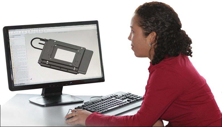
Prototyping
The feasibility of a design is first tested in SolidWorks software, and Finite Element Analysis (FEA) is employed to determine the load capacity of our stages, check for material deformation, and perform other kinds of analyses. The SolidWorks model can then be turned into a sample within 2 - 6 hours using a 3D printer. 3D prints reveal fit and form problems not evident from computer modelling and allow our engineers to get a sense for the finished housing. At the same time, our engineers work to design the layout and firmware for the printed circuit board (PCB). By working on several aspects of the design prototype simultaneously, Thorlabs is able to deliver new products to customers quickly. We also have in-house R&D machining capabilities that allow us to perform quick viability testing of core mechanisms as well as jig design as an alternative to our 3D printing capabilities. This provides our engineers the flexibility to perform rapid prototyping and concurrent engineering. Once an advanced prototype of the proposed product has been assembled, we begin extensive testing following design standards and safety regulations.

Testing
We employ a variety of rigorous tests throughout the design and manufacturing process. Most products undergo soak tests, which simulate use over the lifetime of a product and identify faults that only occur after repeated use. In addition, real-world experimental setups are built on top of our stages, monitored with cameras, and analyzed for behavior in two and three dimensions. We also employ a temperature chamber in a Faraday enclosure to test for drift under repeated temperature cycling. Our linear stages undergo a battery of tests to check their performance in linear translation applications. Rotation stages are subjected to a rigorous array of tests using similar equipment designed for rotational motion. Our testing processes verify that the finished part will meet its design specifications for repeatability, accuracy, and reliability in a variety of contexts.
Production
We begin to consider the manufacturability of each product at the beginning of the design cycle following Design for Manufacturing and Assembly (DFMA) principles. Motion control stages consist of dozens of parts, all of which need to match tight specifications to provide the required performance. In particular, the thermal and mechanical stress relief requirements of the materials used in our systems must be well-matched. To meet these requirements, we take several steps, including extra finishing consisting of grinding and heat treatment to minimize variations between components, tight tolerancing of machined components, and the use of jigs and standardized work to ensure the equipment, processes, and documentation we use result in every part being manufactured the same way. These processes, in addition to our culture of continual feedback, ensure performance specifications are met consistently. We also benefit from an in-house machine shop manned by experienced, knowledgeable machinists.
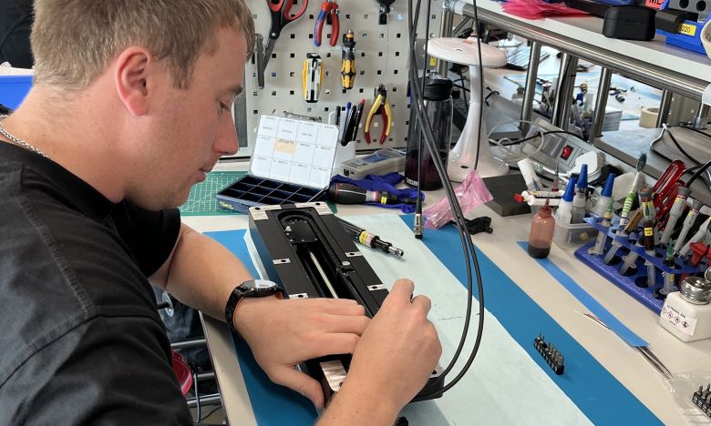
Assembly
To support over 1000 different types of products, our Ely-based assembly team has the flexibility to rapidly shift between assembling different product families in response to customer demand, ensuring that finished products are in our customers' hands as soon as possible. Each cell independently assembles products one at a time, from start to finish, using a right-first-time strategy (also known as one-touch manufacturing). This practical approach avoids waste, bottlenecks, and other problems inherent to batch processes and guarantees that all the parts we ship meet or exceed our stringent specifications. We eliminate variations between builds through Statistical Process Control; the performance of each of our components and finished products is rigorously quantified and analyzed for trends over time. This allows deviations from the design specifications to be identified quickly, permits improved processes to be implemented continuously, and prevents issues that affect product quality and our customers. We follow Lean principles and champion a culture of continuous improvement and end-to-end value streams.
View our brochure to explore
areas of our expertise!

*SolidWorks® is a registered trademark of Dassault Systèmes SolidWorks Corp.
Manufacturing Capabilities
Our production team's overall goal is to utilize the latest technologies, lean manufacturing processes, and quality materials to enable us to rapidly produce consistent best-in-class products. We have made extensive investments in a broad range of dedicated machinery and processes, including large-bed CNC mills, multi-point tooling systems, prototype machinining centers, and fine finishing machines.
Our highly skilled production teams work in dedicated, resourced cells for machining, prepping, construction, and finishing. Cross-training empowers our adaptable production personnel. This in turn allows them to float between different cells flexing our output as production needs dictate.
From start to finish, every person in the manufacturing process is empowered to identify any potential quality issues regardless of whether it affects their operation. By embracing a total-quality approach to our manufacturing, we strive to provide the highest-caliber motion control solutions in the photonics industry.
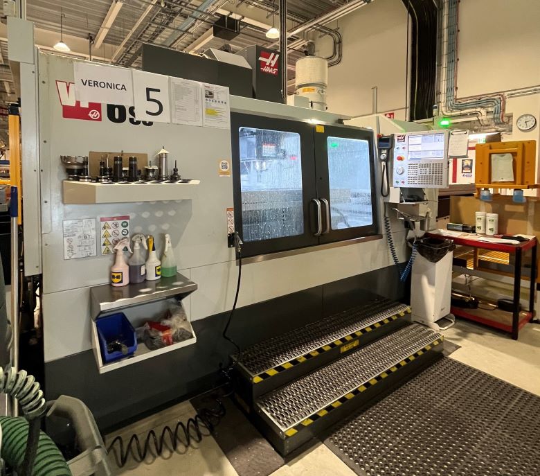
3-Axis and 5-Axis Vertical Mills

Vertical mills are an extremely versatile resource for Thorlabs. We use them to prototype designs, produce initial production runs as the main production line is tooled and validated, and as the main production resource for a wide range of components. Many of our vertical mills have some form of automation that allows them to operate continuously during a shift, and in some cases, between shifts. The automation solutions vary from simple two-pallet systems to 60-pallet systems that can be swapped in and out without tooling or setup.
5-Axis Machining Center for High-Mix, Low-Volume
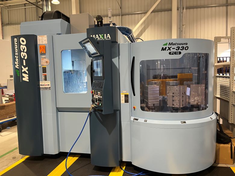
A recent addition, our Matsuura MX-330 5-axis vertical machining center features a 10-fold pallet storage system with 90 unique tools. It offers flexibility for prototyping up to large-scale manufacturing. It can operate with a variety of automation options for low-manpower production. This is the first machine specifically allocated to produce parts within a lean flow, transforming the way we manufacture and allowing us to machine a high-mix, low-volume product basket.
5-Axis Machining Center for Prototyping
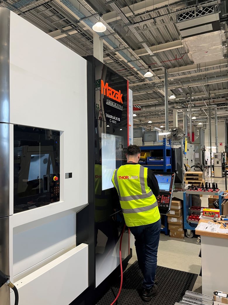
Another recent addition to our machine works in Ely, UK includes the MAZAK Variaxis C-600 vertical 5-axis machining center. This system offers configurability, high-precision, and 2-fold pallet changers for exceptional productivity. The machine is currently being used for prototyping new products that require increased precision and unique tooling specifications.
Long-Bed CNC Machines
In addition to traditional CNC lathes, our team takes advantage of specialized machines with longer beds. Our long-bed CNC lathes are used for machining longer parts, such as stages with extended travel ranges. These machines have extended bed lengths between two to three meters to accommodate long components, delivering robust cutting capabilities while maintaining a minimal footprint.
Laser Engraving
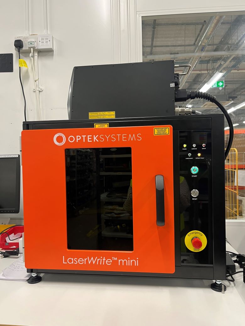
As part of our commitment to developing a continuous flow value stream as part of our lean manufacturing processes, we recently expanded our in-house laser engraving capabilities. Our latest laser engraver has a vision system that allows for faster, more consistent, and more precise engraving of anodized parts.
Horizontal CNC Lathes

Our horizontal CNC lathes are used for many components in our motion control portfolio. These machines provide a versatile range of machining operations. They are capable of different milling tasks, including face milling, end milling, slotting, profiling, contouring, and more. Both the spindle and worktable can be adjusted easily, enabling operators to achieve desired angles and orientations. Horizontal lathes are suitable for complex parts and multi-sided machining.
Wire EDM
The addition of several Wire EDM machines has enabled us to manufacture components that cannot be machined using a mill or lathe. The wire EDM machine ablates conductive material by passing a current from a wire through the material being cut. Since this is a slow, non-contact method of removing material, the wire EDM machine can achieve tolerances that would otherwise be difficult to hold. Additionally, the size of the features that can be created is only limited by the diameter of the wire. Material hardness is an advantage, not a limitation, of the wire EDM; hardened steel can be cut just as easily as aluminum.
Assembly and Lean Processes for Motion Control Systems
 Click to Enlarge
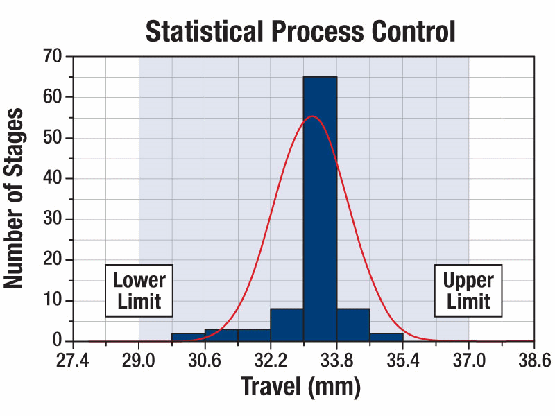
| Travel Range Statisticsa | |
|---|---|
| Mean | 33.18 mm |
| Median | 33.26 mm |
| Minimum | 30.14 mm |
| Maximum | 35.01 mm |
| Standard Deviation | 0.78 mm |
Figure 3.1 Statistical Process Control gives us an early indication when parts begin to move out of tolerance. The region shaded in this graph denotes the tolerance range of this linear translation stage. The red line is a statistical fit that indicates that the mean travel range of our most recently manufactured stages is well within tolerance. Calculated performance information is shown in the Travel Range Statistics table.
Key Capabilities
- Lean Manufacturing Minimizes Costs, Shortens Lead Times, and Eliminates Defects
- Statistical Process Control Proactively Prevents Defective Parts
- Kanban "Just-in-Time" Visual Controls Keep the Right Amount of Components Available
We are always seeking new ways to improve the value stream on the assembly floor. From introducing new production cells to creating dedicated “Dojo Areas” for training to elevate the skill level of all assemblers, we are committed to improving product quality and assembly workflow. Future improvements include expanding our inspection cells and introducing additional cleanroom areas.
Our Ely-based assembly team rapidly shifts between assembling different product families in response to customer demand, ensuring that finished products are in our customers' hands as soon as possible. Each cell independently assembles products one at a time, from start to finish, using a right-first-time strategy (also known as one-touch manufacturing). This practical approach avoids waste, bottlenecks, and other problems inherent to batch processes and guarantees that all the parts we ship meet or exceed our rigorous specifications.
We eliminate variations between builds through Statistical Process Control. The performance of each of our components and finished products is rigorously quantified and analyzed for trends over time. This allows deviations from the design specifications to be identified quickly, enables improved processes to be implemented continuously, and prevents issues that affect product quality and our customers.
Kanbans ensure that components are only ordered when they are needed, on a "just-in-time" basis. This reduces our overhead costs and allows us to pass these savings on to our customers. Once a predetermined quantity of a given component has been consumed, a production order is automatically sent out, allowing us to replace only what we have used. The smaller quantities of on-hand stock also allow us to more easily identify defects and maintain our high quality standards.
Prototyping and Testing of Motion Control Systems

Click for Details
Figure 3.4 Final dimensions and specifications are independently verified.

Click for Details
Figure 3.3 Each finished product is subjected to visual inspection.
Click for Details
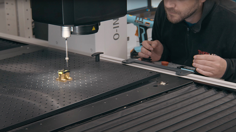
Figure 3.2 A CMM machine is used to inspect a component.
All Designs Are Rigorously Tested for:
- Repeatability
- Accuracy
- Backlash
- Full Travel Range
- Resolution
- Long-Term Drifts
- Lifetime
- Minimum Incremental Motion (MIM)
Specific Products Are Also Measured for:
- Pitch and Yaw (Linear Stages)
- Linearity/Straightness (Linear Stages)
- Runout (Rotation Stages)
- Holding Force (Magnetic Products)
- Electronics:
- Noise Levels
- Electromagnetic Compatibility (EMC)
- Board Tests and Evaluation
Testing Equipment
- Laser Interferometers Accurately Test All Mechanical Specifications
- Real-World Experimental Setups Confirm Stage Performance in a Variety of Applications
- Force Gauges, Torque Gauges, Dial Indicators, and Other Instruments Used to Verify Specifications
- CMM Machine Metrology
- Temperature Chambers
Once a prototype of the proposed design has been assembled, we begin extensive testing on the part. For example, we run endurance tests called "soak tests." Soak tests simulate use over the lifetime of a product and identify faults that only occur after repeated use. In addition, real-world experimental setups are built on top of the stages, monitored with cameras, and analyzed for behavior in two and three dimensions. We also employ a temperature chamber in a Faraday
enclosure to test for drift under repeated temperature cycling.
Our linear stages undergo a battery of tests to check their performance in linear translation applications. For example, we use a Renishaw laser interferometer to verify the straightness of our stages over their entire range of travel. The interferometer also helps us minimize angular displacements (pitch and yaw), which are undesirable in linear translation. Rotation stages are subjected to a similarly rigorous array of tests. In particular, we check rotation stages for undesired out-of-plane motions (runout).
Together, these tests verify that the finished part will meet its design specifications for repeatability, accuracy, and reliability in a variety of contexts, providing a complete picture of the performance of the product.
Specials and Custom Orders

Click to Enlarge
Figure 4.2 Learn More About Our Motion Control Design and Manufacturing
Click to Enlarge
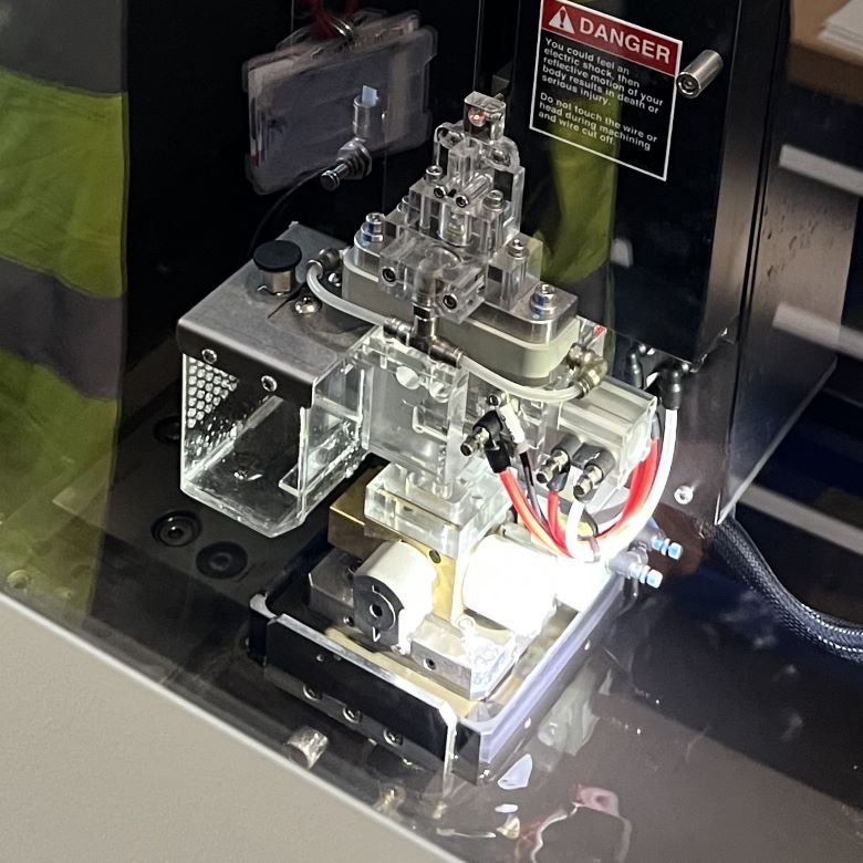
Figure 4.1 Custom 3-Axis Stage
Key Capabilities
- Capabilities for Photonics, Bioscience, and Industrial OEMs
- Linear Stage Modifications: Embedded Electronics, Modified and Custom Hole Patterns, Custom Mounting Accessories, and More
- Removal of Non-Critical Components, Such as Adjusters, to Create Cost-Sensitive Solutions
- Preassembled Subsystems Ready for Integration
- Customized Controller Cards
- Modifications to Standard Products for Additional Functionality and Mounting Flexibility
- Unanodized Parts, Vent Holes, Special Grease, and Other Materials for Applications in Vacuum Down to 10-6 Torr
- Adapters for Different Mounting Configurations or Modifcations to Mounting Accessories
- SolidWorks®* Software Modeling, Finite Element Analysis, and 3D Printing Reduce Lead Time of Custom Designs
- In-House R&D Machining Capabilities: 3- and 5-Axis CNC Machining, Horizontal CNC Machining (Lathe), Wire Erosion Machining (EDM), Sheet Metal Bending, and Laser Cutting
Contact Us for Your Custom and OEM Projects

Leon Chen, Gary Zimberg,
Angelika Karlowatz
Thorlabs Global Sales Directors
If you have a custom or OEM project, we invite you to contact us to discuss how our engineering expertise and manufacturing capabilities can help you achieve your goals.
We look forward to hearing from you!
With more than 30 years of design and production experience, Thorlabs' motion control scientists and engineers can draw from an extensive background to provide positioning systems or components that meet the exact needs of your application. A sample of the services that we offer is listed above and the customization process is described in Figure 4.2. Custom orders receive individualized attention at all steps of the process. Our engineering team and machine shop are uniquely qualified to handle these special requests and final assembly is performed by a dedicated lean manufacturing cell.
From simple, one-off modifications of our standard products to complete, turnkey OEM solutions, our expert team is available to discuss your individual requirements, offer advice, and provide an overview of your choices.
*SolidWorks® is a registered trademark of Dassault Systèmes SolidWorks Corp.
| Posted Comments: | |
| No Comments Posted |