 Products Home
Bi-Telecentric Lenses for Machine Vision
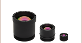
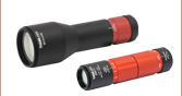
- Ideal for Machine Vision Applications
- Provide Constant Magnification Independent of Object Location
- Lenses Available with Magnification from 0.128X to 1X
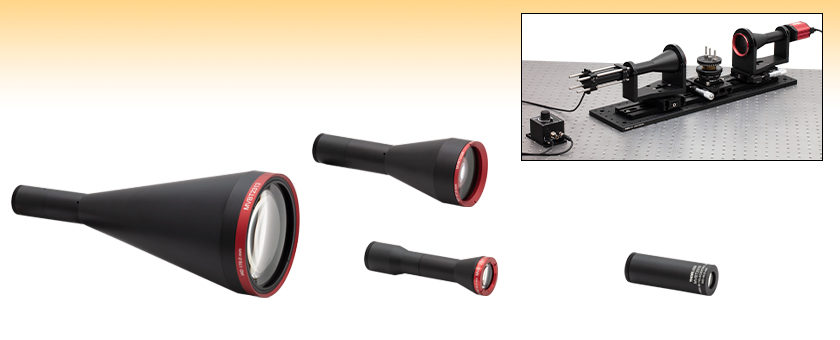
MVBT2313
0.128X Bi-Telecentric Lens
MVBT2324
0.243X Bi-Telecentric Lens
MVBT2353
0.528X Bi-Telecentric Lens
MVBT2310
1.000X Bi-Telecentric Lens
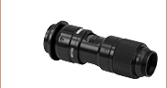
Application Idea
Two MVBT2324 Bi-Telecentric Lenses are mounted with the MVBTC25/M Lens Clamps in an inspection system used for imaging samples, such as the screws shown here.


Please Wait
| Table 1.1 Key Specificationsa | ||||
|---|---|---|---|---|
| Item # | MVBT2313 | MVBT2324 | MVBT2353 | MVBT2310 |
| Magnification | 0.128X ± 1% | 0.243X ± 1% | 0.528X ± 1% | 1.000X ± 1% |
| Working Distanceb | 179.0 mm | 97.9 mm | 44.5 mm | 44.0 mm |
| Depth of Fieldc | ±15 mm | ±11 mm | ±1 mm | ±0.9 mm |
| Field of View (2/3" Format Sensor)d |
85.9 mm | 45.3 mm | 20.8 mm | 11.0 mm |
| Modulation Transfer Function (MTF)e |
>55% | >51% | >51% | >42% |
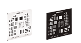
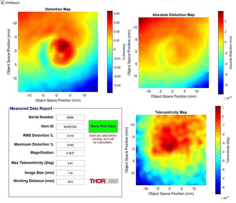
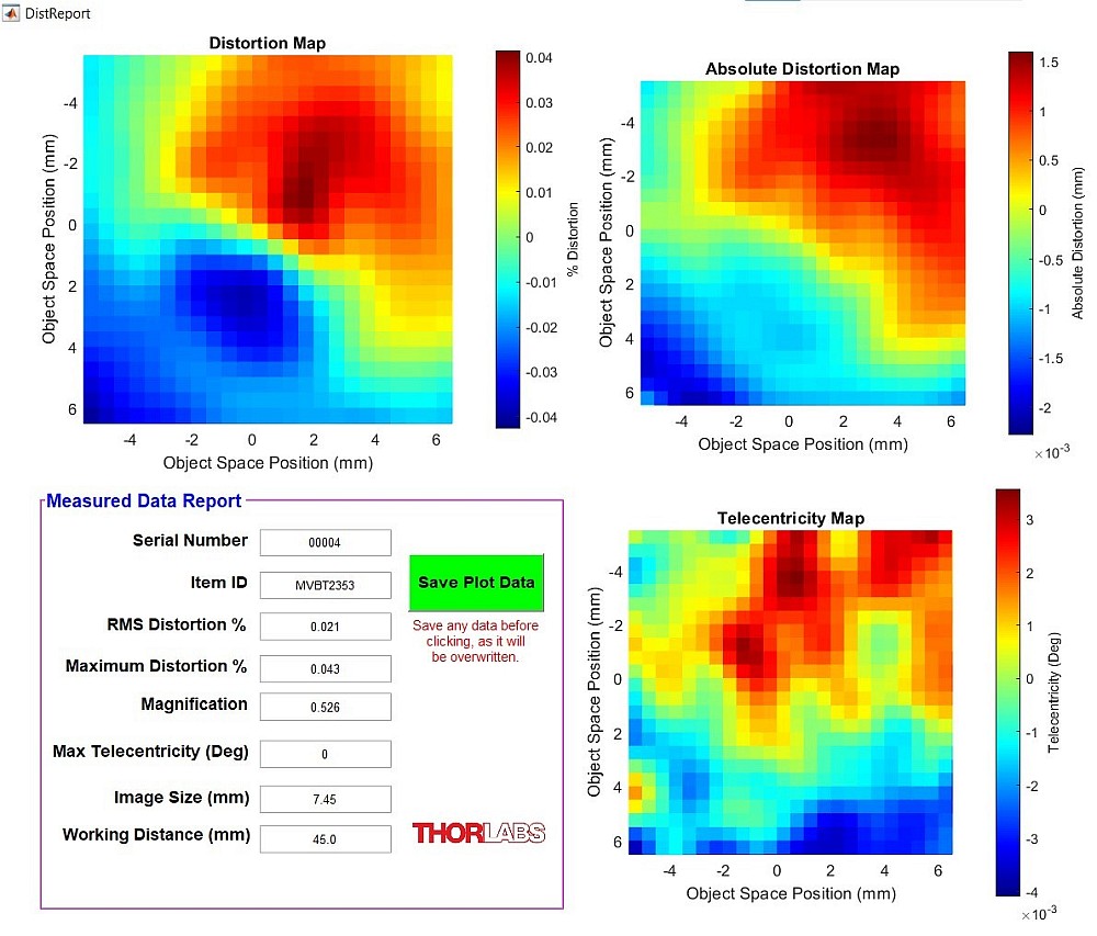
| Sample Test Reportf | 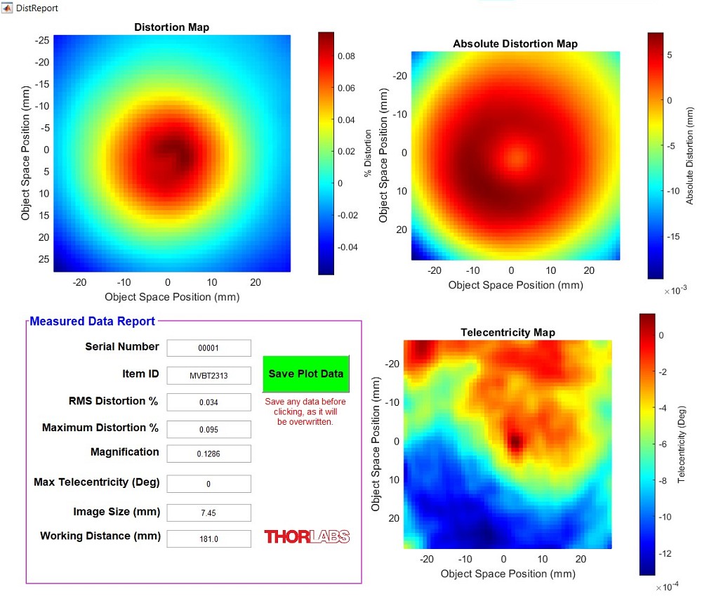 |
 |
 |
 |
| Lens Mount | C-Mount (1.000"-32) | |||
| Lens Lengthg,h | 10.95" (278.1 mm) |
6.74" (171.2 mm) |
5.12" (130.0 mm) |
3.29" (83.5 mm) |
| Lens Housing Diameter at Largest Pointh |
Ø4.50" (Ø114.3 mm) |
Ø2.50" (Ø63.5 mm) |
Ø1.50" (Ø38.1 mm) |
Ø1.20" (Ø30.5 mm) |
| Mass (Weight) | 1.07 kg (2.36 lbs) | 0.36 kg (0.79 lbs) | 0.16 kg (0.35 lbs) | 0.14 kg (0.31 lbs) |
- Complete specifications may be found on the Specs tab.
- Working distance is defined from the center of the depth of field to the first mechanical surface of the lens housing.
- Specified at 70 lp/mm and 50% MTF.
- The field of view is specified in the direction along the sensor diagonal.
- Specified at 70 lp/mm, across the field.
- Click the
 icon to view a sample test report.
 - Not including the threaded C-mount.
- For a mechanical drawing, click the red Docs (
 ) icon next to each item number below.
Features
- Constant Magnification Across the Depth of Field
- Magnifications Available: 0.128X, 0.243X, 0.528X, or 1.000X
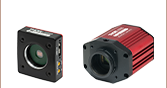
- Compatible with C-Mount Cameras with Sensors Up to 2/3" Format
- Each Lens Ships with a Detailed Test Report Containing Lens Performance Data
- Clamps Available for Easy Installation and Removal of Item #s MVBT2313 and MVBT2324
Thorlabs offers its own line of bi-telecentric lenses for machine vision applications. These lenses offer magnification in both image and object space that is independent of distance (within the depth of field) or the position in the field of view. This attribute is ideal for machine vision applications: when measuring dimensions, a telecentric lens will yield the same measurement regardless of changes in object distance or position. For more details on telecentric lenses and their differences from standard lenses, please see the Telecentric Tutorial tab.
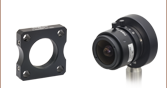
These lenses are designed for 2/3" format sensors, such as those used in a variety of our scientific CMOS cameras. Sensors smaller than 2/3" can also be used but with reduced field of view. The lens housing features external C-mount (1.000"-32) threading on the image side of the lens, which is also compatible with many of our cameras. By using an SM1A10 thread adapter, the C-mount can be mated to internal SM1 (1.035"-40) threads for compatibility with our lens tubes or other SM1-threaded mounts. CS-Mount cameras are compatible with these lenses when using a CML05 CS- to C-Mount adapter.
Each individual lens ships with a detailed test report showing the exact specifications and distortion plots for the lens, including RMS distortion, maximum distortion, magnification, maximum telecentricity, image size, and working distance. Sample reports are available in Table 1.1. Raw data files are available upon request for each lens. These contain maps for distortion, absolute distortion, and telecentricity, as well as a measured data report. Graphs showing typical performance for distortion (%) vs. field height (mm) can be found on the Graphs tab.
Please note that users must take care to properly mount and support the MVBT2313 lens due to its size and weight; this lens should not be solely mounted by its C-mount threads. Lens clamps designed for mounting the MVBT2313 and MVBT2324 lenses are sold below. The clamps feature counterbored slots and holes, which enable a variety of mounting configurations.
| Item # | MVBT2313 | MVBT2324 | MVBT2353 | MVBT2310 |
|---|---|---|---|---|
| Magnification | 0.128X | 0.243X | 0.528X | 1.000X |
| Magnification Tolerance | ±1% | |||
| Working Distancea | 179.0 mm | 97.9 mm | 44.5 mm | 44.0 mm |
| C-Mount Flange Focal Distance | 17.5 mm | |||
| Image Diagonal | 11 mm (2/3" Format) | |||
| Max Distortion | 0.16% | 0.10% | 0.10% | 0.10% |
| Depth of Fieldb | ±15 mm | ±11 mm | ±1 mm | ±0.9 mm |
| System f/# | f/7 | f/8 | f/7 | f/11 |
| Field of View (2/3" Format Sensor)c | 85.9 mm | 45.3 mm | 20.8 mm | 11.0 mm |
| Telecentricity | 0.03° | |||
| Modulation Transfer Function (MTF)d | >55% | >51% | >51% | >42% |
| Coherent Transfer Function (CTF)d | >67% | >63% | >62% | >54% |
| Image NA | 0.071 | 0.062 | 0.071 | 0.045 |
| Object NA | 0.0091 | 0.015 | 0.038 | 0.045 |
| Average Transmittancee | 94% Over 460 - 630 nm | |||
| Lens Mount | C-Mount (1.000"-32) | |||
| Lens Lengthf,g | 10.95" (278.1 mm) | 6.74" (171.2 mm) | 5.12" (130.0 mm) | 3.29" (83.5 mm) |
| Lens Housing Diameter at Largest Pointg |
Ø4.50" (Ø114.3 mm) |
Ø2.50" (Ø63.5 mm) |
Ø1.50" (Ø38.1 mm) |
Ø1.20" (Ø30.5 mm) |
| Mass (Weight) | 1.07 kg (2.36 lbs) | 0.36 kg (0.79 lbs) | 0.16 kg (0.35 lbs) | 0.14 kg (0.31 lbs) |
- Working distance is defined from the center of the depth of field to the first mechanical surface of the lens housing.
- Specified at 70 lp/mm and 50% MTF.
- The field of view is specified in the direction along the sensor diagonal.
- Specified at 70 lp/mm, across the field.
- Specified over 460 - 630 nm.
- Not including the threaded C-mount.
- For a mechanical drawing, click on the red Docs () icon next to each item number below.
These graphs show the theoretically calculated distortion modeling results from Zemax. Each individual lens ships with a detailed test report showing the exact specifications and distortion plots for the lens, including RMS distortion, maximum distortion, magnification, maximum telecentricity, image size, and working distance. A sample report for each lens can be viewed on the Overview tab.
Application
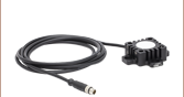
A basic machine vision setup, using two bi-telecentric lenses to inspect the quality of several screws is illustrated in Figure 4.1. Two MVBT2324 0.243x Bi-Telecentric Lenses are mounted in MVBTC25/M 0.243x mounting clamps for easy integration into the inspection system. Light from an LEDBW1 diffuse backlight LED is collimated by one MVBT2324 lens to provide uniform profile illumination. A CS505MU Kiralux 5.0 MP Monochrome CMOS Camera mounted on the other lens captures images of samples. Two XR25P/M linear translation stages and an LJ750/M compact lab jack allow fine adjustment in 3 axes. Additionally, the lab jack top platform can be rotated 360° and locked in place.
This setup can be easily re-configured to suit a variety of inspection needs. The MVBT2324 lenses can be replaced with higher or lower magnification bi-telecentric lenses, a custom asphere-collimated LED can provide an alternate method of illumination, and motorized stages can replace the manual ones. It can also be designed with the optical axis oriented vertically, so flat parts such as gaskets, stampings, and printed circuit boards (PCBs) can be laid flat on a sample holder. For a fully automated inspection and measurement solution, please see Thorlabs' VideoMic® multisensory video measuring system.
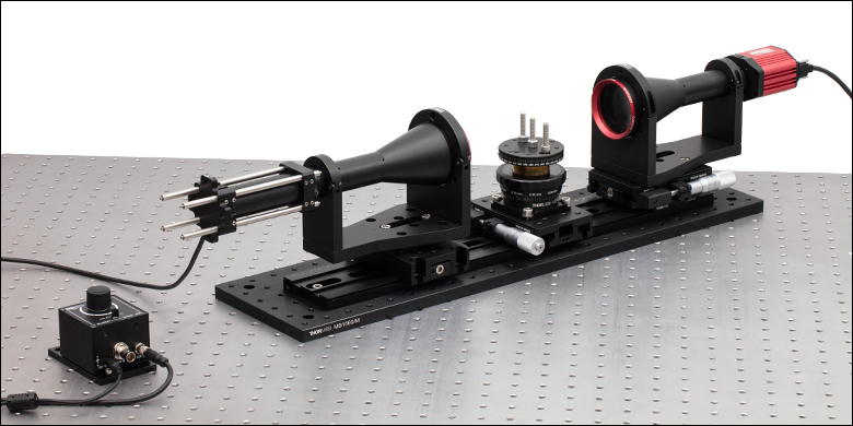
Click to Enlarge
Figure 4.1 Two MVBT2324 0.243x Bi-Telecentric Lenses are mounted with MVBTC25/M 0.243x Bi-Telecentric Lens Clamps in an inspection system. This setup can be used for imaging samples, such as the screws pictured here.

Click to Enlarge
Figure 4.2 Two M6 Screws Imaged with the Inspection System
Imperial Product List
Metric Product List
Telecentric Lenses
Telecentric lenses are designed to have a constant magnification regardless of the object's distance or location in the field of view. This attribute is ideal for many machine vision measurement applications, as measurements of an object's dimensions will be independent of where it is located.
Types of Telecentric Lenses
In order to achieve a telecentric lens design, all of the chief rays (rays from an off-axis point that pass through the center of the aperture stop) have to be parallel to the optical axis in either image space or object space, or both.
For an object space telecentric lens, the chief rays will be parallel to the optical axis on the object's side of the lens (object space). This is accomplished by setting the aperture stop at the front focal plane of the lens, which results in an entrance pupil at infinity. Since chief rays are directed towards the center of the entrance pupil, the chief rays on the object side of the lens will be parallel to the optical axis. An example of an object space telecentric lens is shown in Figure 119A.
For an image space telecentric lens, the chief rays will be parallel to the optical axis on the image's side of the lens (image space). This is accomplished by setting the aperture stop at the back focal plane of the lens, which results in an exit pupil at infinity. Since the chief rays must pass through the center of the exit pupil, the chief rays on the image side of the lens must be parallel to the optical axis. An example of an image space telecentric lens is shown in Figure 119B.
Click to Enlarge
Figure 119A A ray trace through an idealized object space telecentric lens system. Note that the chief rays (the center ray of each color) are parallel to the optical axis in object space, but in image space, the chief rays form an angle with the optical axis.
Click to Enlarge
Figure 119B A ray trace through an idealized image space telecentric lens system. Note that the chief rays (the center ray of each color) are parallel to the optical axis in image space, but in object space, the chief rays form an angle with the optical axis.
For a double telecentric, or bi-telecentric, lens, the front and back focal planes are made to overlap so that the aperture stop is located where both the entrance and exit pupils are at infinity. In a bi-telecentric lens, neither the image or object location will affect the magnification. Thorlabs' telecentric lenses are all bi-telecentric designs. Figure 119C shows an example ray trace through a bi-telecentric lens and illustrates how the chief rays pass through the system.
Click to Enlarge
Figure 119C A ray trace through an idealized bi-telecentric lens system. Note that the chief rays (the center ray of each color) are parallel to the optical axis in both image and object space, which means that the magnification will remain constant regardless of object distance.
Conventional Lenses
In conventional lenses, the entrance and exit pupils are not located at infinity, so the chief rays will not be parallel to the optical axis. In this case, the magnification of the object depends on its distance from the lens and its position in the field of view. Figure 119D shows an example ray trace through a conventional camera lens; notice how the chief rays are angled with respect to the optical axis in both image and object space. Note that both Figures 119C and 119D feature the same lens design; only the aperture stop location was varied to shift the bi-telecentric system to a non-telecentric one.
Click to Enlarge
Figure 119D A ray trace through an idealized conventional camera lens system. Note that the chief rays (the center ray of each color) are not parallel to the optical axis in both image and object space, which means that the magnification will vary with object distance.
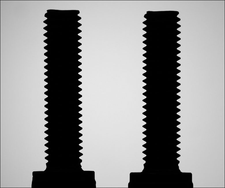
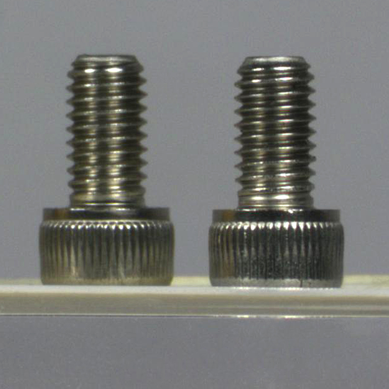
Example Images
Figures 119E and 119F show photographs taken with a bi-telecentric lens and a standard camera lens, respectively. With the telecentric imaging system, the height of the two screws appears to be the same, even though the object planes are separated by approximately 45 mm along the optical axis. With the conventional imaging system, the two screws appear to be different heights, which could result in inaccurate dimensional measurements. A machine vision system using a bi-telecentric lens can offer advantages for dimensional metrology. For example, these lenses can be integrated into our Multi-Sensor Video Measurement Machines.
Click to Enlarge
Figure 119E An image of two identical 8-32 cap screws imaged with our previous generation MVTC23013 0.128X Telecentric Lens. Although the screws appear to be the same size and in the same object plane, they are actually separated by a distance of approximately 45 mm along the optical axis.

Click to Enlarge
Figure 119F The same two screws photographed with our previous-generation MVL7000 conventional zoom lens. The MVL7002 lens provides similar performance. In this image, the perspective error due to the separation of the screws would lead to incorrect height measurements.
| Posted Comments: | |
user
(posted 2025-02-07 06:26:24.973) Hello, is the pupil stop accessible and changeable in this lenses? We are looking for an F/20 system. Thanks, Daniel Seh-Won Ahn
(posted 2025-01-02 11:18:23.707) Could you send me black box file for MVBT2310 compatible with older version of zmax? EGies
(posted 2025-01-13 12:43:53.0) Thank you for contacting Thorlabs. I have reached out to you directly regarding this request. Nathan Leister
(posted 2024-11-13 08:10:58.87) Hi,
we are looking in Hardware and Software for Charactization of our optics. So i want to ask if the device generating the test report for these telecentric optics is availiable at Thorlabs?
Best regards
Nathan ksosnowski
(posted 2024-11-18 12:09:43.0) Hello Nathan, thanks for reaching out to us. We use an in-house design for our characterization system and unfortunately we are not able to offer designs or software for this purpose. I have reached out directly to discuss your application further. user
(posted 2020-11-10 08:25:43.26) Hello, I would like to use this lens in deep UV wavelengths. You specify >96% down to 460 nm. Do you have any information over the transmission below that? What material are the lenses made of and is there any coatings? YLohia
(posted 2020-11-10 11:59:14.0) Hello, thank you for contacting Thorlabs. The transmission of this lens falls down to ~15% at 350 nm. I have reached out to you directly with some data. user
(posted 2019-06-19 02:30:54.85) Hi,I have some question about bi-telecentric lens.
Bi-telecentric means object and image space also telecentric.For MVTC23005 bi-telecentric lens,can I use it in reverse?
like put a LED pattern at back focal point(original image plane),and project the LED pattern image to a sreen at original object plane.
What any problem will happen when I use bi-telecentric lens in reverse?
thank you! llamb
(posted 2019-06-25 10:27:24.0) Thank you for your feedback. While the MVTC23005 can in principle be used in reverse, this may not be very suitable for your application. The image NA is 0.0614, which means only a small amount of LED light would be collected, assuming the LED has a rather large NA. Additionally, the working distance is 530 mm, which can limit your screen's location range. I have reached out to you directly to discuss your application further. lylaana
(posted 2017-06-16 10:36:13.423) Hi, I'am tying to build a simple imaging system for QR code scanner. I'am wondering if this bi-telecentric lens is enough for a CMOS image sensor. Will extra lens be needed?
Thank you very much! tfrisch
(posted 2017-06-27 10:09:12.0) Hello, thank you for contacting Thorlabs. These lenses are all C-mount threaded which is a common thread for a CMOS camera, and they can be used directly with a C-mount camera. Some CMOS cameras are CS-mount which uses the same thread, but a shorter flange focal distance (the distance from the flange of the lens to the sensor). In those cases, an adapter like CML05 can be used. I will reach out to you directly to discuss your application. |

 Zoom
Zoom- Constant Magnification Independent of Object Location
- Magnifications Available: 0.128X, 0.243X, 0.528X, or 1.000X
- Compatible with C-Mount Cameras with Sensors up to 2/3" Format
Thorlabs Bi-Telecentric Lenses are ideal for use in machine vision applications, as measurements of an object's dimensions are independent of the object's distance or position. They are designed for 2/3" format sensors (sensors smaller than 2/3" can also be used but with reduced field of view), such as those used in a variety of our scientific CMOS cameras. The lens housing features external C-mount (1.000"-32) threading on the image side of the lens, which is also compatible with many of our cameras.
Each individual lens ships with a detailed test report showing the exact specifications and distortion plots for the lens, including RMS distortion, maximum distortion, magnification, maximum telecentricity, image size, and working distance.

 Zoom
Zoom
Click to Enlarge
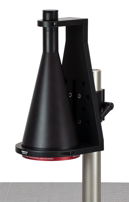
Figure G2.2 Installation of the MVBT2324 Bi-Telecentric Lens in the MVBTC25 Clamp
Click to Enlarge
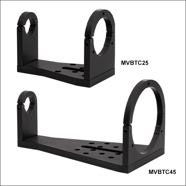
Figure G2.1 The MVBT2313 lens is mounted vertically with the MVBTC45 clamp.
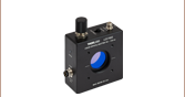
- Accommodates 0.128X or 0.243X Bi-Telecentric Lenses
- Hinged Clamps on Each End Secure the Lenses
- Clamp Base Features Counterbored Slot and Mounting Holes
- Easy Drop-in Installation and Removal of Bi-Telecentric Lenses
Thorlabs' Bi-Telecentric Lens Mounting Clamps allow the allow the MVBT2313 or MVBT2324 Bi-Telecentric Lenses to be easily mounted and removed via the double open-arm design. The MVBTC45(/M) clamp is designed to mount the MVBT2313 0.128X lens, while the MVBTC45(/M) clamp is designed to mount the MVBT2324 0.243X lens. Both arms on the clamps are secured via a 5/64" (2.0 mm) hex captive locking screw. A torque of 3 in-lbs (0.34 Nm) is recommended to apply to the captive locking screws that secure the lens in the clamp.
Each clamp features a counterbored slot that is 3" (75.0 mm) long for the MVBTC45(/M) and 2" (50.0 mm) long for the MVBTC25(/M), as well as counterbored holes for use with 1/4" (M6) cap screws (twelve for the MVBTC45(/M) and six for the MVBTC25(/M)). This enables the clamps to be mounted to a variety of breadboards, posts, rail carriers, and rail accessories, in either a horizontal orientation or a vertical orientation as shown in Figures G2.1 and G2.2. See our full web presentation for more detail.