Optical Component Threading Adapters with C-Mount (1.00"-32) Threads
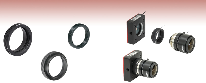
- Integrate C-Mount Threaded Components with Other Industry-Standard Threads
- Adapters Available with Either Internal or External C-Mount Threads
- Mount C-Mount Lenses to CS-Mount Cameras
CML05
5 mm Spacer
SM1A10TS
Thermally Insulating Adapter
with External SM1 Threads
and Internal C-Mount Threads
RMSA5
External C-Mount
Threads and Internal
RMS Threads
CS165MU
SM1A10Z
MVL4WA
SM1A10Z Adapter Connecting an MVL4WA C-Mount Lens to the SM1-Threaded Aperture of a Zelux® Camera

Please Wait
Click to Enlarge
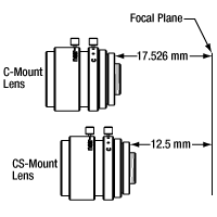
Figure 1.2 C- vs. CS-Mount Flange Focal Distances
Click to Enlarge
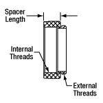
Figure 1.1 Spacer Length Schematic
C-Mount Threaded Optical Component Adapters
This page contains all of our Optical Component Thread Adapters that feature C-mount (1.00"-32) threading. Adapters featuring either internal or external threads are available.
The CS- and C-mount standards both use 1.00"-32 threads, but C-mount lenses have a flange focal distance (FFD) that is 5 mm longer than CS-mount lenses, as illustrated in the Figure 1.2. Spacer length is defined for each adapter as the distance depicted by Figure 1.1. The CML05 adapter is 5 mm long and acts as a spacer, enabling the use of C-mount lenses with CS-mount cameras; see the Insights tab for more details.
These adapters are a subset of our entire line of optical component thread adapters. To view our entire line, please see our Interactive Adapters Selection Guide.
| Adapters with External C-Mount (1.00"-32) and Internal Industry-Standard Threads |
||||
|---|---|---|---|---|
| Item # | Typical Application | External Threadsa | Internal Threads | |
| SM05A2 | Mount a C-Mount Camera Body to an SM05 Lens Tube |
C-Mount (1.00"-32) | SM05 (0.535"-40) | |
| CMA1 | Mount M19 x 0.5 Thermal Imaging Lens to C-Mount Cage Plate |
C-Mount (1.00"-32) | M19 x 0.5 | |
| RMSA5 | Mount RMS Objective to Camera | C-Mount (1.00"-32) | RMS (0.800"-36) | |
| CMA2 | Mount M25 x 0.5 Thermal Imaging Lens to C-Mount Cage Plate |
C-Mount (1.00"-32) | M25 x 0.5 | |
| SM1A9 | Mount a C-Mount Camera Body to an SM1 Lens Tube |
C-Mount (1.00"-32) | SM1 (1.035"-40) | |
| SM1A9TSb | Mount a C-Mount Camera Body to an SM1 Lens Tube |
C-Mount (1.00"-32) | SM1 (1.035"-40) | |
| TMA5 | Mount a C-Mount Camera Body to a T-Mount Lens |
C-Mount (1.00"-32) | T-Mount (M42 x 0.75) |
|
| SM2A31 | Mount SM2 Lens Tube to Camera with C-Mount Thread |
C-Mount (1.00"-32) | SM2 (2.035"-40) | |
| 5 mm Spacer with C-Mount (1.00"-32) Threads | ||||
|---|---|---|---|---|
| Item # | Typical Application | External Threads | Internal Threads | |
| CML05 | Mount C-Mount Camera Lens to CS-Mount Camera |
C-Mounta (1.00"-32) | C-Mounta (1.00"-32) | |
| Adapters with Internal C-Mount (1.00"-32) and External Industry-Standard Threads |
||||
|---|---|---|---|---|
| Item # | Typical Application | External Threads | Internal Threadsa | |
| RMSA6 | Integrate Camera Lens to Microscope | RMS (0.800"-36) | C-Mount (1.00"-32) | |
| SM1A10 | Mount CS-Mount Camera Lens to Zelux® Camera | SM1 (1.035"-40) | C-Mount (1.00"-32) | |
| SM1A10TSb | Mount Camera Lens to SM1 Lens Tube |
SM1 (1.035"-40) | C-Mount (1.00"-32) | |
| SM1A10A | Mount C-Mount Camera Lens to Kiralux® and Quantalux® Cameras | SM1 (1.035"-40) | C-Mount (1.00"-32) | |
| DC-CS1 | Mount Camera Lens to SM1 Lens Tube |
SM1 (1.035"-40) | C-Mount (1.00"-32) | |
| SM1A10Zc | Mount Camera Lens to Zelux Camera |
SM1 (1.035"-40) | C-Mount (1.00"-32) | |
| TMA6 | Mount Camera Lens to T-Mount Camera |
T-Mount (M42 x 0.75) | C-Mount (1.00"-32) | |
| SM2A54 | Mount Camera Lens to SM2 Lens Tube |
SM2 (2.035"-40) | C-Mount (1.00"-32) | |
| Adapters with External C-Mount (1.00"-32) and External Industry-Standard Threads |
||||
|---|---|---|---|---|
| Item # | Typical Application | |||
| SM05A1 | Mount a C-Mount Camera Body to an SM05 Lens Tube |
|||
| CMT2 | Mate Two C-Mount Extension Tubes |
|||
| CMT10 | Mate Two C-Mount Extension Tubes |
|||
| SM1A39 | Mount a C-Mount Camera Body to an SM1 Lens Tube |
|||
| SM2A55 | Mount a C-Mount Camera Body to an SM2 Lens Tube |
|||
| Adapter with Internal C-Mount (1.00"-32) and Internal Industry-Standard Threads |
||||
|---|---|---|---|---|
| Typical Application | External Threadsa | External Threadsa | ||
| CMT1 | Mate Two C-Mount Extension Tubes |
C-Mount (1.00"-32) | C-Mount (1.00"-32) | |
Click to Enlarge
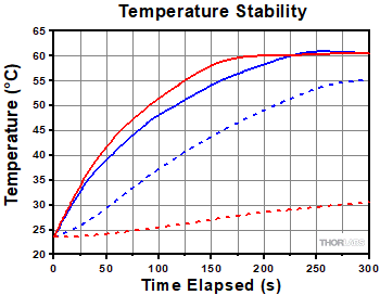
Figure 3.1 Temperature Stability of SM1 Lens Tubes Connected with Either a Thermally Isolating Adapter (Red Lines) or an
Aluminum Adapter (Blue Lines)
| Legend | |||
|---|---|---|---|
| |
Heated SM1 Lens Tube with Aluminum Adapter | |
Heated SM1 Lens Tube with Delrin® Adapter |
| |
Unheated SM1 Lens Tube with Aluminum Adapter | |
Unheated SM1 Lens Tube with Delrin® Adapter |
Thermal Insulation Experiment
An experiment was conducted to compare the thermal isolation of our thermally insulating adapters (SM1A4TS, SM1A9TS, SM1A3TS, and SM1A10TS) presented at the bottom of this page with that of our traditional aluminum adapters. During the experiment, an aluminum adapter and a thermally isolating black Delrin®* adapter were each used to connect two lens tubes. Then, one of the lens tubes was externally heated to 60 °C using a foil heating element that had been attached to that lens tube’s outer surface.
During the heating process, simultaneous temperature readings were recorded in 30 second intervals for both the heated and unheated lens tube in each system. The measured results are shown in the plot in Figure 3.1. From the graph, it is clearly evident that there is far less heat transfer when using one of our thermally isolating adapters to connect two lens tubes than exists when using an aluminum adapter.
*Delrin® is a registered trademark of DuPont Polymers, Inc.
| Table 122E SM05 Threading: Ø1/2" Lens Tubes, 16 mm Cage Systems | |||
|---|---|---|---|
| External Thread, 0.535"-40.0 UNS-2A | Internal Thread, 0.535"-40.0 UNS-2B | ||
| Max Major Diameter | 0.5340" | Min Major Diameter | 0.5350" |
| Min Major Diameter | 0.5289" | Min Pitch Diameter | 0.5188" |
| Max Pitch Diameter | 0.5178" | Max Pitch Diameter | 0.5230" |
| Min Pitch Diameter | 0.5146" | Min Minor Diameter (and 83.3% of Thread) | 0.508" |
| Max Minor Diameter | 0.5069" | Max Minor Diameter (and 64.9% of Thread) | 0.514" |
| Table 122F RMS Threading: Objective, Scan, and Tube Lenses | |||
|---|---|---|---|
| External Thread, 0.800"-36.0 UNS-2A | Internal Thread, 0.800"-36.0 UNS-2B | ||
| Max Major Diameter | 0.7989" | Min Major Diameter | 0.8000" |
| Min Major Diameter | 0.7934" | Min Pitch Diameter | 0.7820" |
| Max Pitch Diameter | 0.7809" | Max Pitch Diameter | 0.7866" |
| Min Pitch Diameter | 0.7774" | Min Minor Diameter (and 83.3% of Thread) | 0.770" |
| Max Minor Diameter | 0.7688" | Max Minor Diameter (and 64.9% of Thread) | 0.777" |
| Table 122G C-Mount Threading: Machine Vision Lenses, CCD/CMOS Cameras | |||
|---|---|---|---|
| External Thread, 1.000"-32.0 UN-2A | Internal Thread, 1.000"-32.0 UN-2B | ||
| Max Major Diameter | 0.9989" | Min Major Diameter | 1.0000" |
| Min Major Diameter | 0.9929" | Min Pitch Diameter | 0.9797" |
| Max Pitch Diameter | 0.9786" | Max Pitch Diameter | 0.9846" |
| Min Pitch Diameter | 0.9748" | Min Minor Diameter (and 83.3% of Thread) | 0.966" |
| Max Minor Diameter | 0.9651" | Max Minor Diameter (and 64.9% of Thread) | 0.974" |
| Table 122H SM1 Threading: Ø1" Lens Tubes, 30 mm Cage Systems | |||
|---|---|---|---|
| External Thread, 1.035"-40.0 UNS-2A | Internal Thread, 1.035"-40.0 UNS-2B | ||
| Max Major Diameter | 1.0339" | Min Major Diameter | 1.0350" |
| Min Major Diameter | 1.0288" | Min Pitch Diameter | 1.0188" |
| Max Pitch Diameter | 1.0177" | Max Pitch Diameter | 1.0234" |
| Min Pitch Diameter | 1.0142" | Min Minor Diameter (and 83.3% of Thread) | 1.008" |
| Max Minor Diameter | 1.0068" | Max Minor Diameter (and 64.9% of Thread) | 1.014" |
| Table 122J SM30 Threading: Ø30 mm Lens Tubes | |||
|---|---|---|---|
| External Thread, M30.5 x 0.5 – 6H/6g | Internal Thread, M30.5 x 0.5 – 6H/6g | ||
| Max Major Diameter | 30.480 mm | Min Major Diameter | 30.500 mm |
| Min Major Diameter | 30.371 mm | Min Pitch Diameter | 30.175 mm |
| Max Pitch Diameter | 30.155 mm | Max Pitch Diameter | 30.302 mm |
| Min Pitch Diameter | 30.059 mm | Min Minor Diameter (and 83.3% of Thread) | 29.959 mm |
| Max Minor Diameter | 29.938 mm | Max Minor Diameter (and 64.9% of Thread) | 30.094 mm |
| Table 122K SM1.5 Threading: Ø1.5" Lens Tubes | |||
|---|---|---|---|
| External Thread, 1.535"-40 UNS-2A | Internal Thread, 1.535"-40 UNS-2B | ||
| Max Major Diameter | 1.5339" | Min Major Diameter | 1.535" |
| Min Major Diameter | 1.5288" | Min Pitch Diameter | 1.5188" |
| Max Pitch Diameter | 1.5177" | Max Pitch Diameter | 1.5236" |
| Min Pitch Diameter | 1.5140" | Min Minor Diameter (and 83.3% of Thread) | 1.508" |
| Max Minor Diameter | 1.5068" | Max Minor Diameter (and 64.9% of Thread) | 1.514" |
| Table 122L SM2 Threading: Ø2" Lens Tubes, 60 mm Cage Systems | |||
|---|---|---|---|
| External Thread, 2.035"-40.0 UNS-2A | Internal Thread, 2.035"-40.0 UNS-2B | ||
| Max Major Diameter | 2.0338" | Min Major Diameter | 2.0350" |
| Min Major Diameter | 2.0287" | Min Pitch Diameter | 2.0188" |
| Max Pitch Diameter | 2.0176" | Max Pitch Diameter | 2.0239" |
| Min Pitch Diameter | 2.0137" | Min Minor Diameter (and 83.3% of Thread) | 2.008" |
| Max Minor Diameter | 2.0067" | Max Minor Diameter (and 64.9% of Thread) | 2.014" |
| Table 122M SM3 Threading: Ø3" Lens Tubes | |||
|---|---|---|---|
| External Thread, 3.035"-40.0 UNS-2A | Internal Thread, 3.035"-40.0 UNS-2B | ||
| Max Major Diameter | 3.0337" | Min Major Diameter | 3.0350" |
| Min Major Diameter | 3.0286" | Min Pitch Diameter | 3.0188" |
| Max Pitch Diameter | 3.0175" | Max Pitch Diameter | 3.0242" |
| Min Pitch Diameter | 3.0133" | Min Minor Diameter (and 83.3% of Thread) | 3.008" |
| Max Minor Diameter | 3.0066" | Max Minor Diameter (and 64.9% of Thread) | 3.014" |
| Table 122N SM4 Threading: Ø4" Lens Tubes | |||
|---|---|---|---|
| External Thread, 4.035"-40 UNS-2A | Internal Thread, 4.035"-40.0 UNS-2B | ||
| Max Major Diameter | 4.0337" | Min Major Diameter | 4.0350" |
| Min Major Diameter | 4.0286" | Min Pitch Diameter | 4.0188" |
| Max Pitch Diameter | 4.0175" | Max Pitch Diameter | 4.0245" |
| Min Pitch Diameter | 4.0131" | Min Minor Diameter (and 83.3% of Thread) | 4.008" |
| Max Minor Diameter | 4.0066" | Max Minor Diameter (and 64.9% of Thread) | 4.014" |
Insights into Mounting Lenses to Thorlabs' Scientific Cameras
Scroll down to read about compatibility between lenses and cameras of different mount types, with a focus on Thorlabs' scientific cameras.
- Can C-mount and CS-mount cameras and lenses be used with each other?
- Do Thorlabs' scientific cameras need an adapter?
- Why can the FFD be smaller than the distance separating the camera's flange and sensor?
Click here for more insights into lab practices and equipment.
Can C-mount and CS-mount cameras and lenses be used with each other?
Click to Enlarge
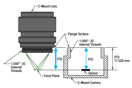
Figure 194A C-mount lenses and cameras have the same flange focal distance (FFD), 17.526 mm. This ensures light through the lens focuses on the camera's sensor. Both components have 1.000"-32 threads, sometimes referred to as "C-mount threads".
Click to Enlarge
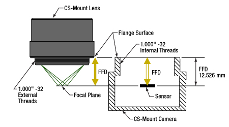
Figure 194B CS-mount lenses and cameras have the same flange focal distance (FFD), 12.526 mm. This ensures light through the lens focuses on the camera's sensor. Their 1.000"-32 threads are identical to threads on C-mount components, sometimes referred to as "C-mount threads."
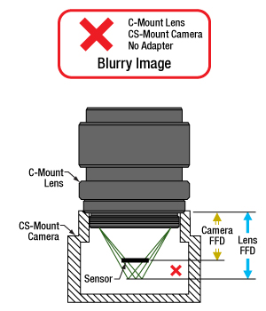
The C-mount and CS-mount camera system standards both include 1.000"-32 threads, but the two mount types have different flange focal distances (FFD, also known as flange focal depth, flange focal length, register, flange back distance, and flange-to-film distance). The FFD is 17.526 mm for the C-mount and 12.526 mm for the CS-mount (Figures 194A and 194B, respectively).
Since their flange focal distances are different, the C-mount and CS-mount components are not directly interchangeable. However, with an adapter, it is possible to use a
Mixing and Matching
C-mount and CS-mount components have identical threads, but lenses and cameras of different mount types should not be directly attached to one another. If this is done, the lens' focal plane will not coincide with the camera's sensor plane due to the difference in FFD, and the image will be blurry.
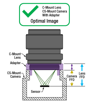
With an adapter, a C-mount lens can be used with a CS-mount camera (Figures 194C and 194D). The adapter increases the separation between the lens and the camera's sensor by 5.0 mm, to ensure the lens' focal plane aligns with the camera's sensor plane.
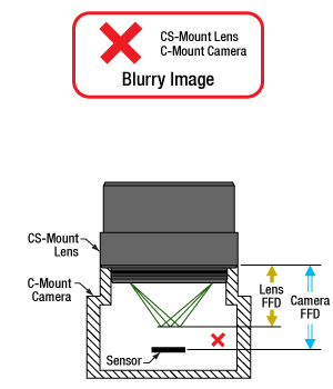
In contrast, the shorter FFD of CS-mount lenses makes them incompatible for use with C-mount cameras (Figure 194E). The lens and camera housings prevent the lens from mounting close enough to the camera sensor to provide an in-focus image, and no adapter can bring the lens closer.
It is critical to check the lens and camera parameters to determine whether the components are compatible, an adapter is required, or the components cannot be made compatible.
1.000"-32 Threads
Imperial threads are properly described by their diameter and the number of threads per inch (TPI). In the case of both these mounts, the thread diameter is 1.000" and the TPI is 32. Due to the prevalence of C-mount devices, the 1.000"-32 thread is sometimes referred to as a "C-mount thread." Using this term can cause confusion, since CS-mount devices have the same threads.
Measuring Flange Focal Distance
Measurements of flange focal distance are given for both lenses and cameras. In the case of lenses, the FFD is measured from the lens' flange surface (Figures 194A and 194B) to its focal plane. The flange surface follows the lens' planar back face and intersects the base of the external 1.000"-32 threads. In cameras, the FFD is measured from the camera's front face to the sensor plane. When the lens is mounted on the camera without an adapter, the flange surfaces on the camera front face and lens back face are brought into contact.
Click to Enlarge
Figure 194E A CS-mount lens is not directly compatible with a C-mount camera, since the light focuses before the camera's sensor. Adapters are not useful, since the solution would require shrinking the flange focal distance of the camera (blue arrow).
Click to Enlarge
Figure 194D An adapter with the proper thickness moves the C-mount lens away from the CS-mount camera's sensor by an optimal amount, which is indicated by the length of the purple arrow. This allows the lens to focus light on the camera's sensor, despite the difference in FFD.
Click to Enlarge
Figure 194C A C-mount lens and a CS-mount camera are not directly compatible, since their flange focal distances, indicated by the blue and yellow arrows, respectively, are different. This arrangement will result in blurry images, since the light will not focus on the camera's sensor.
Date of Last Edit: July 21, 2020
Do Thorlabs' scientific cameras need an adapter?
Click to Enlarge
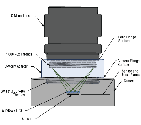
Figure 194F An adapter can be used to optimally position a C-mount lens on a camera whose flange focal distance is less than 17.526 mm. This sketch is based on a Zelux camera and its SM1A10Z adapter.
Click to Enlarge
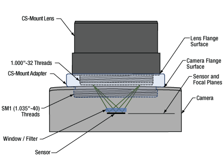
Figure 194G An adapter can be used to optimally position a CS-mount lens on a camera whose flange focal distance is less than 12.526 mm. This sketch is based on a Zelux camera and its SM1A10 adapter.
All Kiralux™ and Quantalux® scientific cameras are factory set to accept C-mount lenses. When the attached C-mount adapters are removed from the passively cooled cameras, the
The SM1 threads integrated into the camera housings are intended to facilitate the use of lens assemblies created from Thorlabs components. Adapters can also be used to convert from the camera's C-mount configurations. When designing an application-specific lens assembly or considering the use of an adapter not specifically designed for the camera, it is important to ensure that the flange focal distances (FFD) of the camera and lens match, as well as that the camera's sensor size accommodates the desired field of view (FOV).
Made for Each Other: Cameras and Their Adapters
Fixed adapters are available to configure the Zelux cameras to meet C-mount and CS-mount standards (Figures 194F and 194G). These adapters, as well as the adjustable C-mount adapters attached to the passively cooled Kiralux and Quantalux cameras, were designed specifically for use with their respective cameras.
While any adapter converting from SM1 to
The position of the lens' focal plane is determined by a combination of the lens' FFD, which is measured in air, and any refractive elements between the lens and the camera's sensor. When light focused by the lens passes through a refractive element, instead of just travelling through air, the physical focal plane is shifted to longer distances by an amount that can be calculated. The adapter must add enough separation to compensate for both the camera's FFD, when it is too short, and the focal shift caused by any windows or filters inserted between the lens and sensor.
Flexiblity and Quick Fixes: Adjustable C-Mount Adapter
Passively cooled Kiralux and Quantalux cameras consist of a camera with SM1 internal threads, a window or filter covering the sensor and secured by a retaining ring, and an adjustable C-mount adapter.
A benefit of the adjustable C-mount adapter is that it can tune the spacing between the lens and camera over a 1.8 mm range, when the window / filter and retaining ring are in place. Changing the spacing can compensate for different effects that otherwise misalign the camera's sensor plane and the lens' focal plane. These effects include material expansion and contraction due to temperature changes, positioning errors from tolerance stacking, and focal shifts caused by a substitute window or filter with a different thickness or refractive index.
Adjusting the camera's adapter may be necessary to obtain sharp images of objects at infinity. When an object is at infinity, the incoming rays are parallel, and location of the focus defines the FFD of the lens. Since the actual FFDs of lenses and cameras may not match their intended FFDs, the focal plane for objects at infinity may be shifted from the sensor plane, resulting in a blurry image.
If it is impossible to get a sharp image of objects at infinity, despite tuning the lens focus, try adjusting the camera's adapter. This can compensate for shifts due to tolerance and environmental effects and bring the image into focus.
Date of Last Edit: Aug. 2, 2020
Why can the FFD be smaller than the distance separating the camera's flange and sensor?
Click to Enlarge
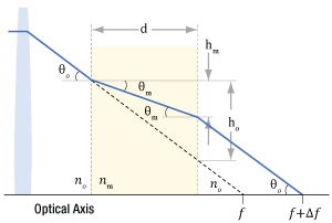
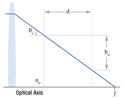
Figure 194J Refraction causes the ray's angle with the optical axis to be shallower in the medium than in air (θm vs. θo ), due to the differences in refractive indices (nm vs. no ). After travelling a distance d in the medium, the ray is only hm closer to the axis. Due to this, the ray intersects the axis Δf beyond the f point.;
Click to Enlarge
Figure 194H A ray travelling through air intersects the optical axis at point f. The ray is ho closer to the axis after it travels across distance d. The refractive index of the air is no .
| Table 194L Example of Calculating Focal Shift | |||
|---|---|---|---|
| Known Information | |||
| C-Mount FFD | f | 17.526 mm | |
| Total Glass Thickness | d | ~1.6 mm | |
| Refractive Index of Air | no | 1 | |
| Refractive Index of Glass | nm | 1.5 | |
| Lens f-Number | f / N | f / 1.4 | |
| Parameter to Calculate |
Exact Equations | Paraxial Approximation |
|
| θo | 20° | ||
| ho | 0.57 mm | --- | |
| θm | 13° | --- | |
| hm | 0.37 mm | --- | |
| Δf | 0.57 mm | 0.53 mm | |
| f + Δf | 18.1 mm | 18.1 mm | |
| Table 194K Equations for Calculating the Focal Shift (Δf ) | ||
|---|---|---|
| Angle of Ray in Air, from Lens f-Number ( f / N ) |  |
|
| Change in Distance to Axis, Travelling through Air (Figure 194H) |  |
|
| Angle of Ray to Axis, in the Medium (Figure 194J) |
 |
|
| Change in Distance to Axis, Travelling through Optic (Figure 194J) |  |
|
| Focal Shift Caused by Refraction through Medium (Figure 194J) | Exact Calculation |
 |
| Paraxial Approximation |
 |
|
Click to Enlarge
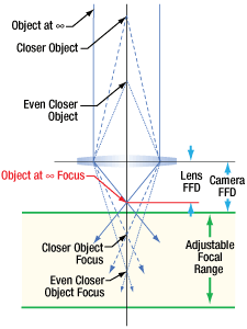
Figure 194N Tolerance and / or temperature effects may result in the lens and camera having different FFDs. If the FFD of the lens is shorter, images of objects at infinity will be excluded from the focal range. Since the system cannot focus on them, they will be blurry.
Click to Enlarge
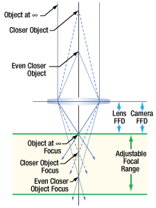
Figure 194M When their flange focal distances (FFD) are the same, the camera's sensor plane and the lens' focal plane are perfectly aligned. Images of objects at infinity coincide with one limit of the system's focal range.
Flange focal distance (FFD) values for cameras and lenses assume only air fills the space between the lens and the camera's sensor plane. If windows and / or filters are inserted between the lens and camera sensor, it may be necessary to increase the distance separating the camera's flange and sensor planes to a value beyond the specified FFD. A span equal to the FFD may be too short, because refraction through windows and filters bends the light's path and shifts the focal plane farther away.
If making changes to the optics between the lens and camera sensor, the resulting focal plane shift should be calculated to determine whether the separation between lens and camera should be adjusted to maintain good alignment. Note that good alignment is necessary for, but cannot guarantee, an in-focus image, since new optics may introduce aberrations and other effects resulting in unacceptable image quality.
A Case of the Bends: Focal Shift Due to Refraction
While travelling through a solid medium, a ray's path is straight (Figure 194H). Its angle
When an optic with plane-parallel sides and a higher refractive index
While travelling through the optic, the ray approaches the optical axis at a slower rate than a ray travelling the same distance in air. After exiting the optic, the ray's angle with the axis is again θo , the same as a ray that did not pass through the optic. However, the ray exits the optic farther away from the axis than if it had never passed through it. Since the ray refracted by the optic is farther away, it crosses the axis at a point shifted Δf beyond the other ray's crossing. Increasing the optic's thickness widens the separation between the two rays, which increases Δf.
To Infinity and Beyond
It is important to many applications that the camera system be capable of capturing high-quality images of objects at infinity. Rays from these objects are parallel and focused to a point closer to the lens than rays from closer objects (Figure 194J). The FFDs of cameras and lenses are defined so the focal point of rays from infinitely distant objects will align with the camera's sensor plane. When a lens has an adjustable focal range, objects at infinity are in focus at one end of the range and closer objects are in focus at the other.
Different effects, including temperature changes and tolerance stacking, can result in the lens and / or camera not exactly meeting the FFD specification. When the lens' actual FFD is shorter than the camera's, the camera system can no longer obtain sharp images of objects at infinity (Figure 194N). This offset can also result if an optic is removed from between the lens and camera sensor.
An approach some lenses use to compensate for this is to allow the user to vary the lens focus to points "beyond" infinity. This does not refer to a physical distance, it just allows the lens to push its focal plane farther away. Thorlabs' Kiralux™ and Quantalux® cameras include adjustable C-mount adapters to allow the spacing to be tuned as needed.
If the lens' FFD is larger than the camera's, images of objects at infinity fall within the system's focal range, but some closer objects that should be within this range will be excluded. This situation can be caused by inserting optics between the lens and camera sensor. If objects at infinity can still be imaged, this can often be acceptable.
Not Just Theory: Camera Design Example
The C-mount, hermetically sealed, and TE-cooled Quantalux camera has a fixed 18.1 mm spacing between its flange surface and sensor plane. However, the FFD (f ) for C-mount camera systems is 17.526 mm. The camera's need for greater spacing becomes apparent when the focal shift due to the window soldered into the hermetic cover and the glass covering the sensor are taken into account. The results recorded in Table 194L show that both exact and paraxial equations return a required total spacing of 18.1 mm.
Date of Last Edit: July 31, 2020
| Posted Comments: | |
user
(posted 2019-09-12 11:26:28.347) I suggest that you consider releasing a modified "customer-inspired" version of this part. Increase the OD to 2 inches, smooth or SM2 thread, and you've got yourself a camera with a lens, perfectly mounted and aligned inside a 2" lens tube. A slotted lens tube comes in very handy to turn focusing and iris rings on the lens. (In order to do it now, I had shave off the knurled surface on CML05, then it can go into CP12, then shave off corners of the CP12 so that it can go inside 2" lens tube.) llamb
(posted 2019-09-12 05:19:41.0) Thank you for your feedback. We will consider this new product suggestion. Perhaps you can also consider our SM2A54 adapter to achieve a similar function for mounting C-Mounted threaded camera lenses inside an SM2 lens tube. I have reached out to you directly to discuss your application further. user
(posted 2019-06-17 15:40:15.657) My application needs 1.042-32 (dia and thread) . I could not find one in your inventory that matches my need. The closest I get is SM05A2 which is 1.000-32. I am wondering if a piece of my spec can me made as a customer inspired product. If so how much may be the unit price. Thanks in advance for your time.
Regards
Radha K Pattnaik YLohia
(posted 2019-06-17 04:16:53.0) Hello Radha, thank you for contacting Thorlabs. Custom items can be requested by emailing your local Thorlabs Technical Support team. I'm reaching out to you directly to discuss the possibility of offering this. user
(posted 2015-10-20 09:12:42.373) It would also be nice to have a SM05 to M12 adapter (lenses with an M12 thread seem common for small USB cameras). besembeson
(posted 2015-10-27 06:42:26.0) Response from Bweh at Thorlabs USA. Thanks for your feedback. We will review this suggestion for S-mount (M12x0.5) adapters which is relevant for board-level integration of small lenses and small USB cameras like you mentioned. |
 Products Home



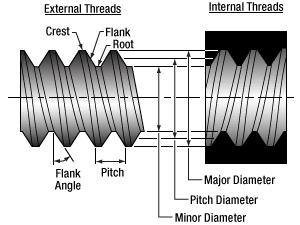


 C-Mount-Threaded Adapters