 Products Home / Optical Systems / Objective Lenses, Scan Lenses, and Tube Lenses / Infinity-Corrected Tube Lenses
Infinity-Corrected Tube Lenses
- For Use with Infinity-Corrected Objectives
- Available in Focal Lengths Used by Thorlabs, Nikon, Leica, Mitutoyo, Olympus, and Zeiss
- Designs for Widefield and Laser Scanning Applications
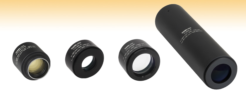
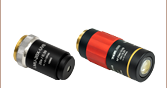
TTL200-UVB
Widefield Tube Lens,
f = 200 mm, 240 - 360 nm
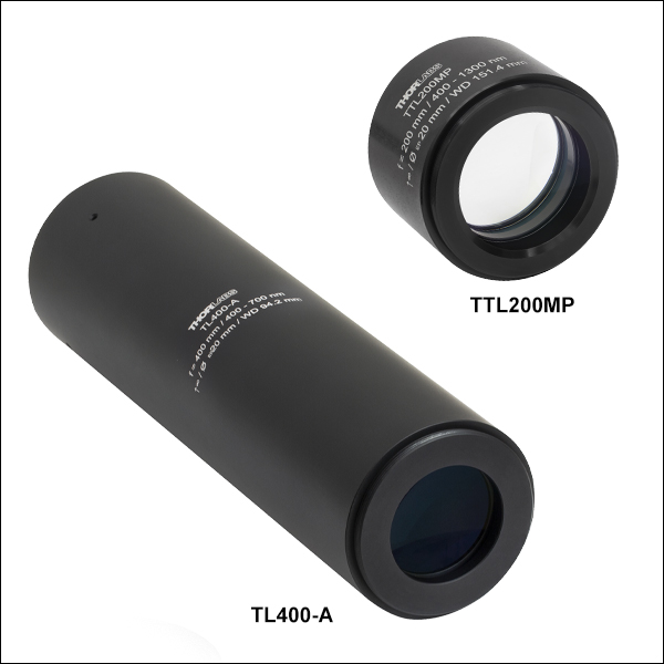
TTL200MP
Laser Scanning Tube Lens,
f = 200 mm, 400 - 2000 nm
TTL180-A
Widefield Tube Lens, f = 180 mm, 400 - 750 nm
TL600-A
Laser Scanning Tube Lens,
f = 600 mm, 400 - 700 nm


Please Wait
| Objective Lens Selection Guide |
|---|
| Objectives |
| Super Apochromatic Microscope Objectives Microscopy Objectives, Dry Microscopy Objectives, Oil Immersion Physiology Objectives, Water Dipping or Immersion Phase Contrast Objectives Long Working Distance Objectives Reflective Microscopy Objectives UV Focusing Objectives VIS and NIR Objectives |
| Scan Lenses and Tube Lenses |
| Scan Lenses F-Theta Scan Lenses Infinity-Corrected Tube Lenses |
| Webpage Features | |
|---|---|
 |
Zemax black box files (both directions) for all tube lenses except the ITL200 can be accessed by clicking this icon below. |
| Tube Lens Options | ||
|---|---|---|
| Tube Lens Type | Effective Focal Length | Available Wavelength Ranges |
| Widefield | 200 mm | UV |
| Visible | ||
| Visible and NIR | ||
| NIR | ||
| 180 mm | Visible | |
| 165 mm | ||
| 100 mm | ||
| Laser Scanning and Widefield | 600 mm | Visible |
| 400 mm | ||
| 300 mm | ||
| 200 mm | Visible | |
| Visible and NIR | ||
| NIR | ||
Click for Details
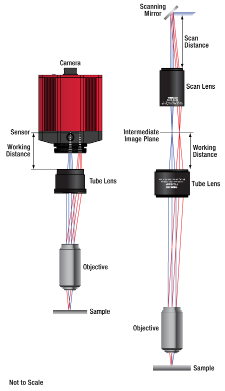
Figure 1.1 Widefield imaging tube lenses take the collimated light from an infinity-corrected microscope and focus it onto the sensor of a camera, as shown on the left. Laser scanning tube lenses can be used in telecentric systems to scan a laser spot across a sample.
Features
- Tube Lenses for Widefield Imaging
- True Imaging Lenses for Forming a Well-Corrected Infinity Optical System
- Apochromatically Corrected for Diffraction-Limited Performance Across the Field of View
- Better Overall Aberration Correction than Standard Achromats
- 200 mm, 180 mm, 165 mm, or 100 mm Focal Length
- Telecentric Tube Lenses for Laser Scanning and Widefield Imaging
- Infinity-Corrected Design
- Forms a Telecentric System When Paired with an SL50 Scan Lens
- 600 mm, 400 mm, 300 mm, or 200 mm Focal Length
- AR Coatings for High Transmission Through UV, Visible, and NIR Wavelength Ranges
- Compatible with Thorlabs, Nikon, Leica, Mitutoyo, Olympus, and Zeiss Objectives
- Diffraction-Limited Optical Performance
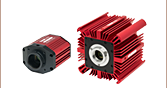
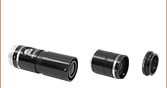
These infinity-corrected tube lenses are designed for use with infinity-corrected objectives from all major manufacturers, including the dry, oil immersion, and physiology microscope objectives sold by Thorlabs. Designed for high-resolution imaging, biomedical, machine vision, and laser scanning applications, these lenses can be aligned in pairs to create relays, combined with objectives to create different effective magnification ratios at a scientific camera, used as drop-in replacements for tube lenses in existing systems, or integrated into DIY Cerna® Microscopes and other home-built microscopy setups to generate high-quality images.
Standard Widefield Tube Lenses
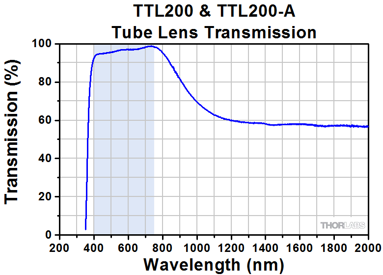
Our widefield tube lenses are AR-coated for high transmission and provide diffraction-limited axial color performance for the UV, visible, and NIR wavelength ranges; see the Specs tab for performance data. Their effective focal lengths correspond to the design focal lengths of popular objectives (see the Magnification & FOV tab for details). The TTL200 series of tube lenses are specifically designed to offer a wider diffraction-limited axial color range than the ITL200 tube lens. Specifications for all lenses can be found on the Specs tab, as well as Zemax black box files for all lenses except the ITL200.
Telecentric Tube Lenses for Laser Scanning and Widefield Imaging
Our laser scanning tube lenses are optimized for laser scanning applications, such as confocal laser scanning, two-photon microscopy, and three-photon microscopy. These lenses create a telecentric system when paired with our SL50-CLS2, SL50-2P2, and SL50-3P scan lenses, for use in point-by-point galvo scanning of the object plane. These lenses can also be used for widefield imaging over their specified wavelength ranges.
Our standard widefield tube lenses for the visible wavelength range can also be used for laser scanning purposes when paired with the CLS-SL visible scan lens for example. However, using a standard tube lens in a scanning configuration will limit the unvignetted field size, since the tube lens must be placed at the telecentric pupil distance from the objective (e.g., 250 mm for the TTL200 lens), rather than the intended pupil distance of the tube lens.
Microscope and Objective Optical Compatibility
Microscope manufacturers design their systems with one of several standard tube lens focal lengths, including 200 mm (typical for Thorlabs, Nikon, Leica, and Mitutoyo microscopes), 180 mm (typical for Olympus microscopes), and 165 mm (typical for Zeiss microscopes). Similarly, microscope objectives are designed to provide the magnification engraved on the housing when used with a tube lens of the appropriate standard focal length. We offer infinity-corrected tube lenses in all of these focal lengths so that home-built microscope systems may make use of these industry standards.
Alternatively, objectives and tube lenses with different design focal lengths may be combined to create different magnification ratios at the camera without compromising the axial color correction. We offer four tube lenses with non-standard focal lengths that can be used to change the magnification of an existing system. To calculate the system magnification for different tube lens and objective combinations, see the Magnification & FOV tab.
Tube Lenses for Widefield Imaging
| Table 2.1 Specifications | ||||||||||||
|---|---|---|---|---|---|---|---|---|---|---|---|---|
| Item # | TTL200-UVB | TTL200 | TTL200-A | TTL200-S8 | TTL200-B | ITL200 | TTL180-A | TTL165-A | TTL100-A | |||
| Effective Focal Length | 200 mm ± 1% | 200 mm ± 1% | 200 mm | 180 mm ± 1% | 165 mm ± 1% | 100 mm ± 1% | ||||||
| Working Distancea,b | 176.4 mm | 148.6 mm | 151.8 mm | 148 mm | 133.5 mm | 120.6 mm | 63.1 mm | |||||
| Pupil Distancec | 50 - 80 mmd | 70 - 170 mm | 70 - 170 mm | 50 - 150 mm | 50 - 150 mm | 0 - 100 mm | ||||||
| Field Size at Image Plane | Ø24 mm | Ø22 mme | Not Available | Ø22 mme | Ø22 mme | Ø15 mme | ||||||
| Entrance Pupil | Ø13 mm (Max)d | Ø20 mm | Ø22 mm | Not Available | Ø18 mm | Ø16 mm | Ø14 mm | |||||
| Lens Design | Apochromatic | Apochromatic | Apochromatic | Apochromatic | Apochromatic | Apochromatic | ||||||
| Design Wavelength Rangeb | 248 - 700 nm | 400 - 750 nm | 400 - 750 nm | 400 - 2000 nm | 650 - 1050 nm | Visible Wavelengths | 400 - 750 nm | 400 - 750 nm | 450 - 750 nm | |||
| AR Coating Range | 240 - 360 nm | 350 - 700 nm | Broadband Single-Layer MgF2 Coating |
650 - 1050 nm | Visible Wavelengths | 350 - 700 nm | 350 - 700 nm | 350 - 700 nm | ||||
| Axial Color | Diffraction Limited | Diffraction Limited | Not Available | Diffraction Limited |
||||||||
| Resolution | Diffraction Limitedf | Diffraction Limitedf | Not Available | Diffraction Limitedf | ||||||||
| Surface Quality | 20-10 Scratch-Dig |
60-40 Scratch-Dig | Not Available | 60-40 Scratch-Dig | ||||||||
| External Threading | M32 x 0.5 (Top) SM1.5 (Top and Bottom) |
M38 x 0.5 Bottom Only |
SM2 Top and Bottom |
M38 x 0.5 Bottom Only |
SM2 Top and Bottom |
SM2 Top and Bottom |
SM2 Top and Bottom |
|||||
| Housing Length | 49.5 mm | 28.0 mm | 28.0 mm | 31.1 mm | 30.9 mm | 33.5 mm | ||||||
| Performance Data (Click for Graph) | ||||||||||||
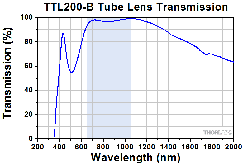
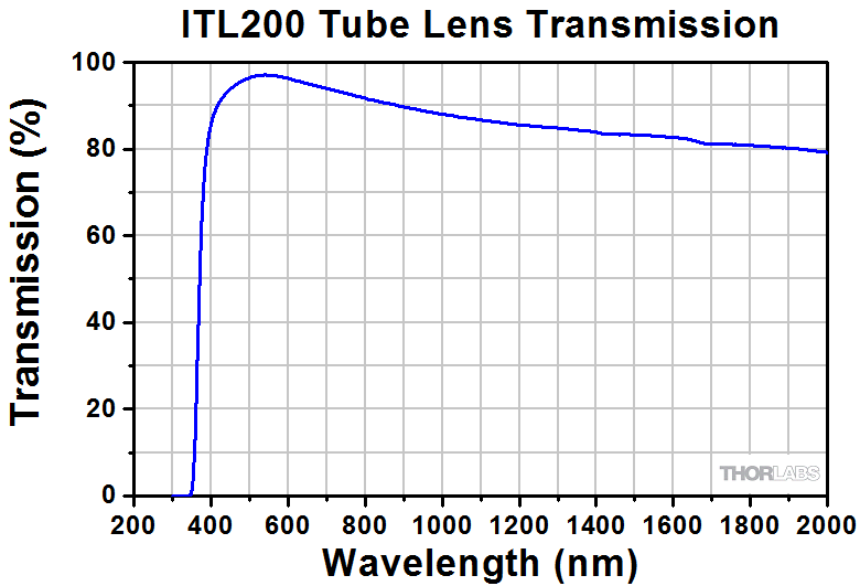
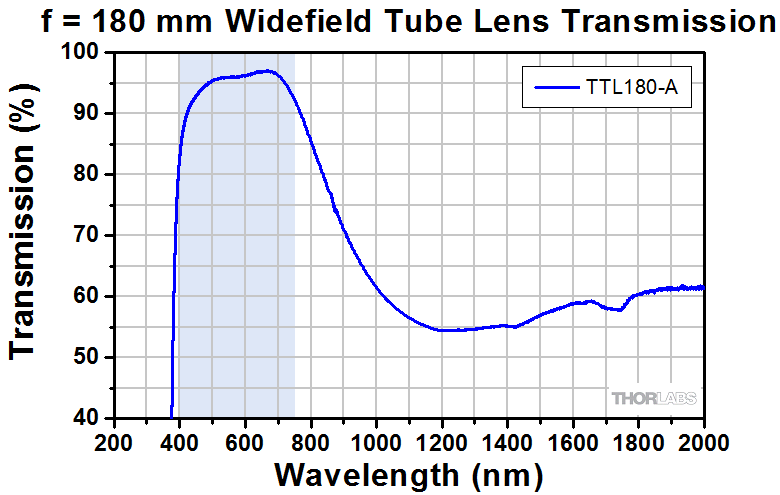
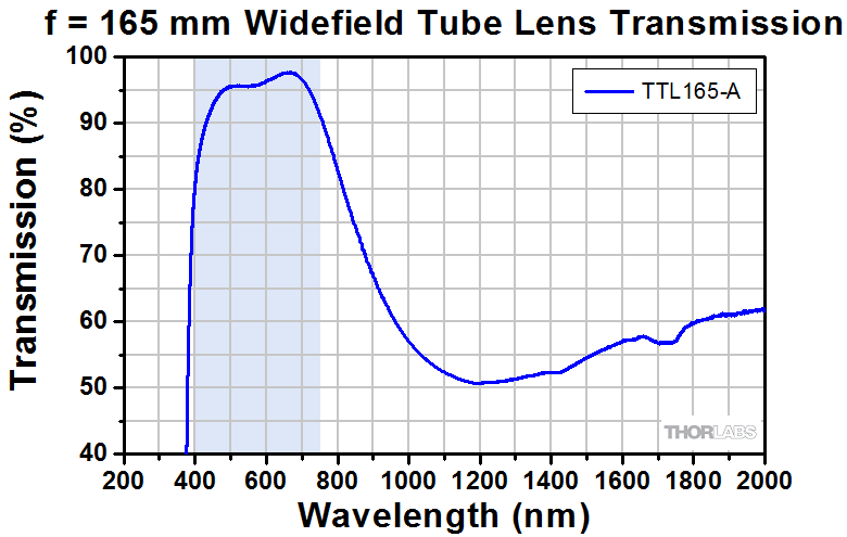
| Transmission | 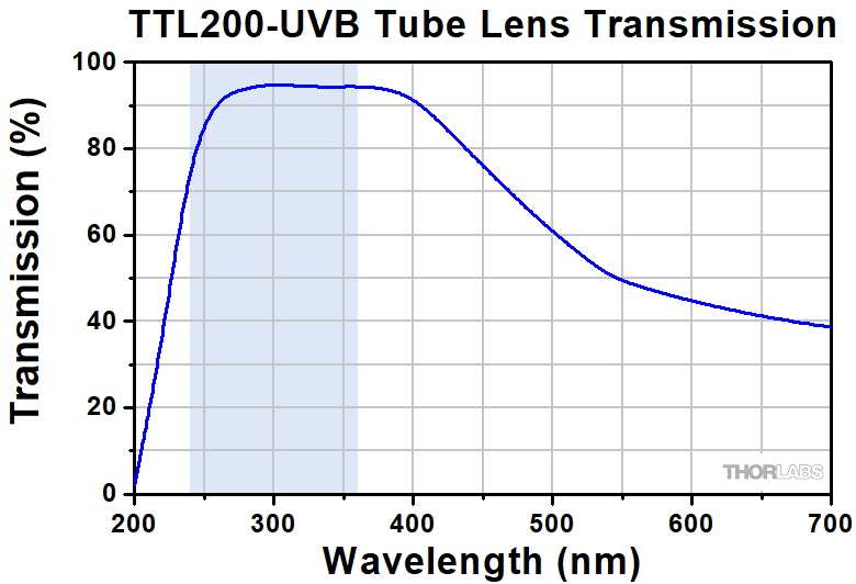 |
 |
 |
 |
 |
 |
 |
 |
||||
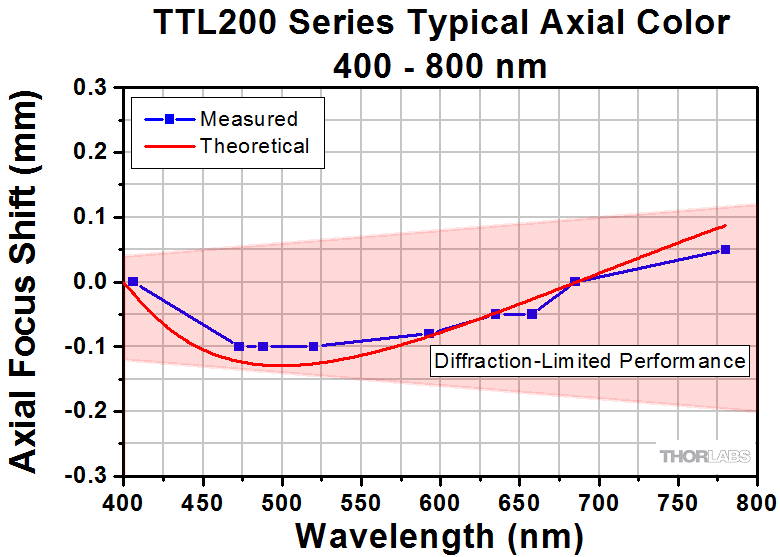
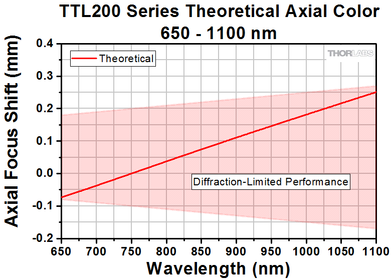
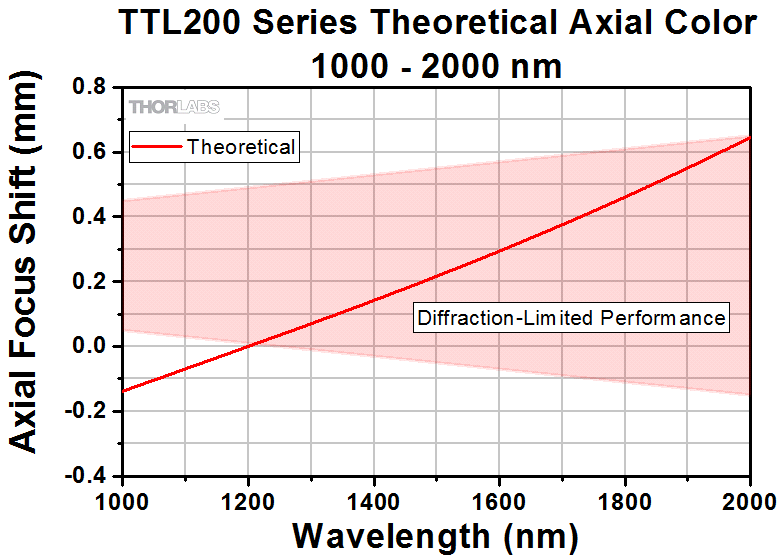
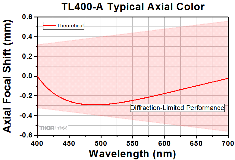
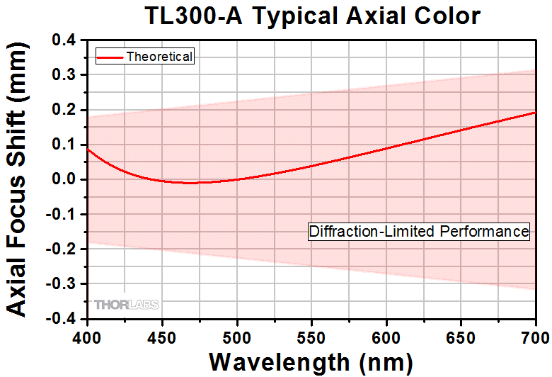
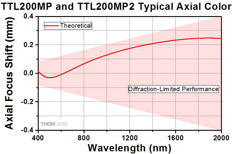
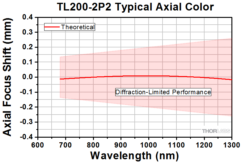
| Axial Color |  |
|
Not Available |  |
 |
 |
||||||
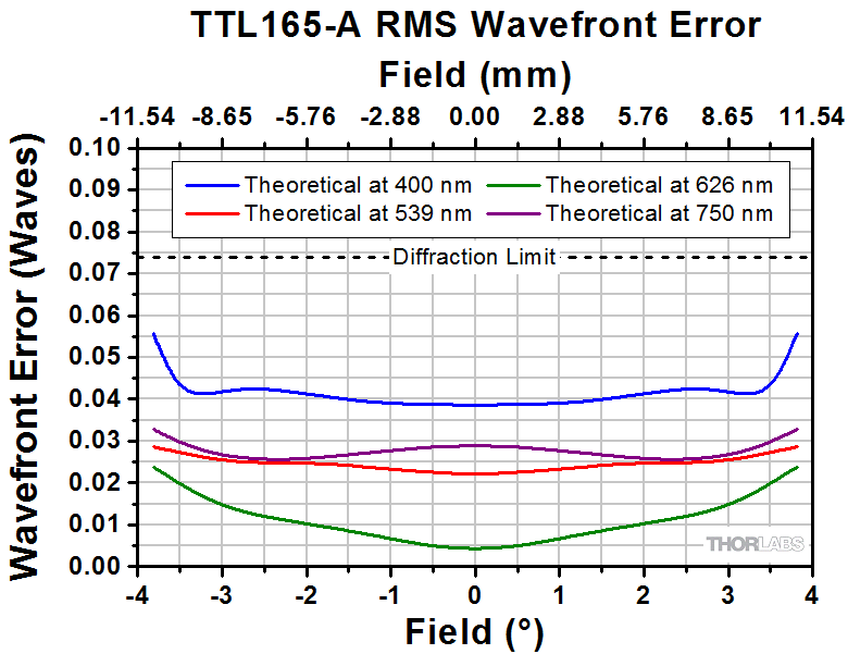
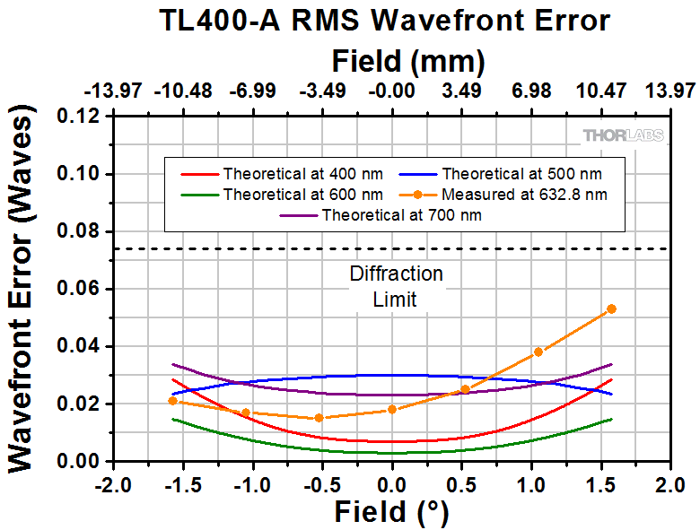
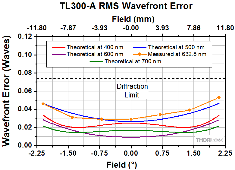
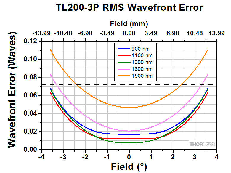
| RMS Wavefront Error |  |
 |
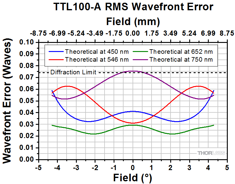
Not Available |  |
 |
 |
||||||
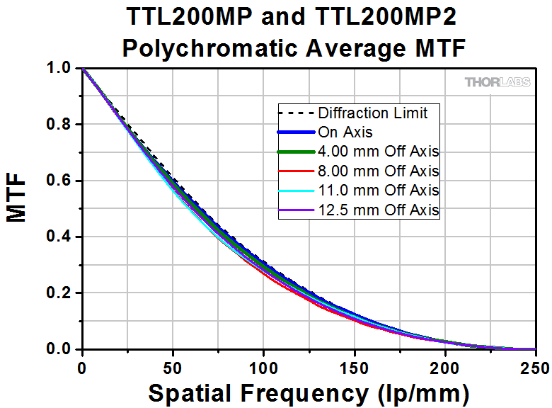
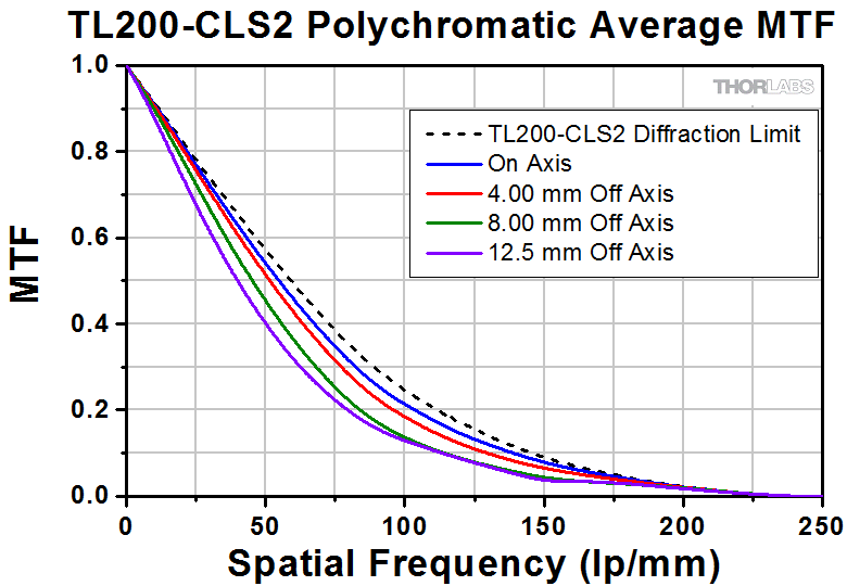
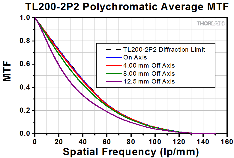
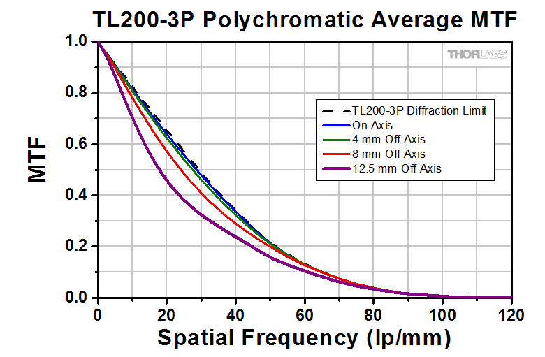
| MTF | 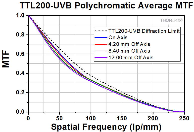 |
 |
Not Available | 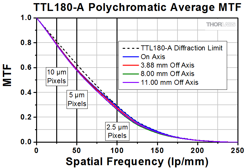 |
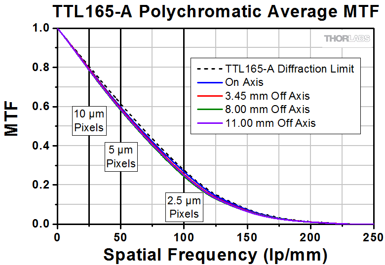 |
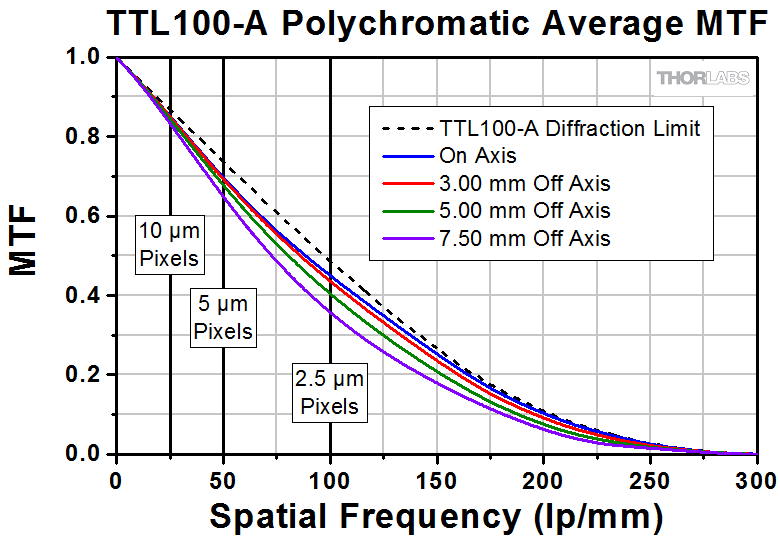 |
||||||
| Distortion | 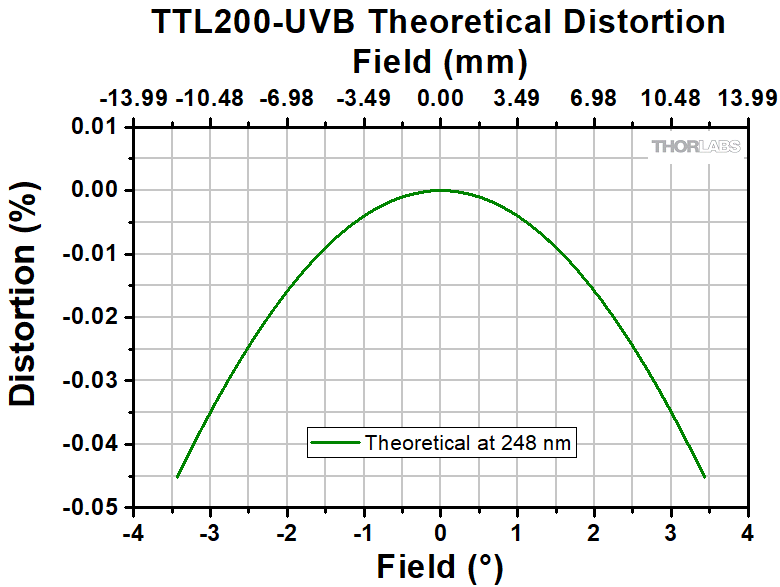 |
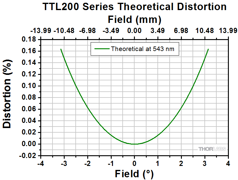 |
Not Available | 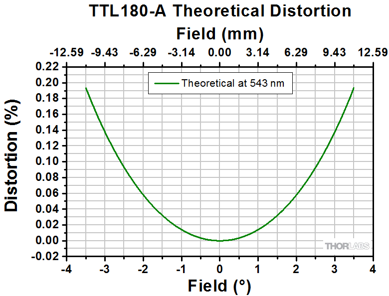 |
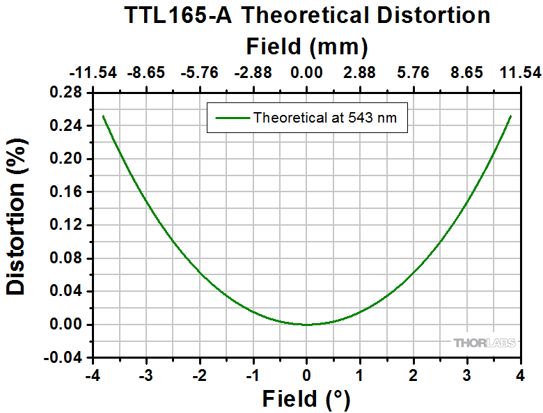 |
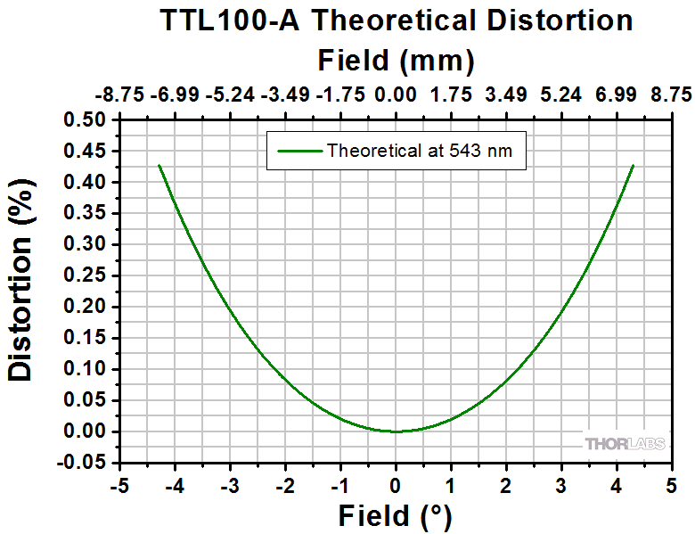 |
||||||
| Data | Excel Spreadsheet |
Excel Spreadsheet |
Excel Spreadsheet |
Excel Spreadsheet |
Excel Spreadsheet |
Excel Spreadsheet |
||||||
| Zemax Black Box Files | Forward Backward |
Forward Backward |
Forward Backward |
Forward Backward |
Forward Backward |
Not Available | Forward Backward |
Forward Backward |
Forward Backward |
|||
Click To Enlarge
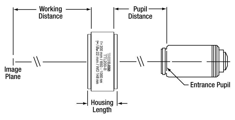
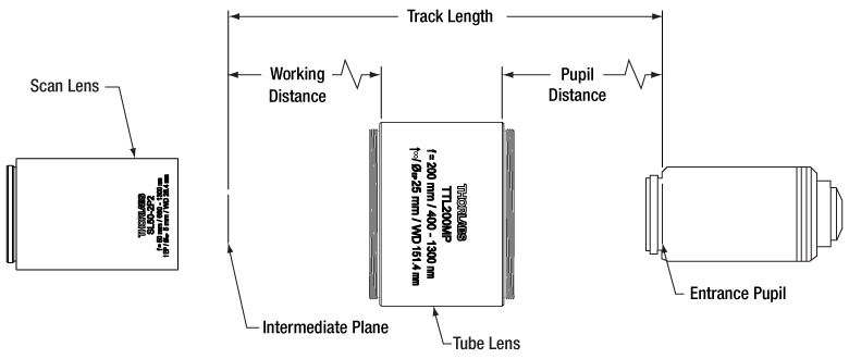
Figure 2.2 This schematic shows the working distance and pupil distance for the TTL series and ITL200 tube lenses. The working distance corresponds to the distance from the top surface of the housing to the image plane. The pupil distance, defined as the distance between the bottom edge of the tube lens housing and the entrance pupil of the objective, can be set anywhere within the range specified in Table 2.1, since the rays from the objective are in parallel bundles. If the tube lens is too close or far, the image may suffer from aberrations.
Tube Lenses for Laser Scanning and Widefield Imaging
| Table 2.3 Specifications | ||||||||
|---|---|---|---|---|---|---|---|---|
| Item # | TL600-A | TL400-A | TL300-A | TTL200MP | TTL200MP2 | TL200-CLS2 | TL200-2P2 | TL200-3P |
| Effective Focal Length | 600 mm | 400 mm | 300 mm | 200 mm | ||||
| Working Distancea | 94.2 mm | 151.4 mm | 180.9 mm | |||||
| Pupil Distanceb | 123 mm (Telecentric) | 228 mm (Telecentric) | 189.1 mm (Telecentric) | |||||
| Field Size (Diffraction Limited) |
Ø22 mm | 16.3 mm x 16.3 mm (FN23) for 656.3 - 1100 nm; 14.1 mm x 14.1 mm (FN20) at 587.6 nm; 7.8 mm x 7.8 mm (FN11) at 486.1 nm |
15.5 mm x 15.5 mm (FN22) for 680 - 1300 nm |
15.5 mm x 15.5 mm (FN22) for 900 - 1600 nm; 12.4 mm x 12.4 mm (FN 17.6) at 1900 nm |
||||
| Track Length | 420 mm (Nominal) | 409 mm (Nominal) | ||||||
| Entrance Pupil | Ø20 mm | |||||||
| Lens Design | Apochromatic | |||||||
| Design Wavelength Range |
400 - 700 nm | 400 - 2000 nm | 450 - 1100 nm | 680 - 1300 nm | 900 - 1900 nm | |||
| AR Coating Range | 400 - 700 nm | 400 - 1300 nm | Broadband Single-Layer MgF2 Coating | 450 - 1100 nm | 680 - 1300 nm | 900 - 1900 nm | ||
| f/# | 30 | 20 | 15 | 10 | ||||
| Clear Aperture | Ø30.7 mm | Ø36.8 mm | Ø47.0 mm | |||||
| Axial Color | Diffraction Limited | |||||||
| F-Theta Distortion | <0.5% | <0.2% | <0.3% | |||||
| Threading | External SM2 Threads (Top and Bottom) | Internal SM2 Threads on Top External SM2 Threads on Bottom |
||||||
| Housing Length |
205.7 mm | 44.1 mm | 41.6 mm | |||||
| Performance Data (Click for Graph) | ||||||||
| Transmission | 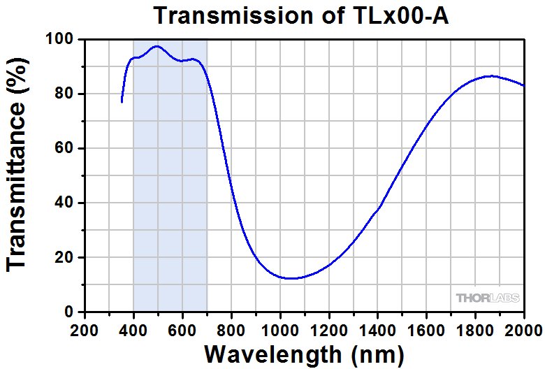 |
 |
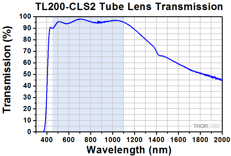 |
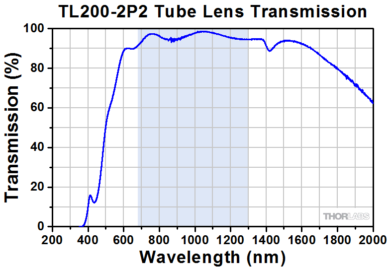 |
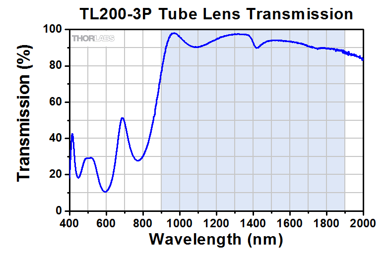 |
|||
| Axial Color | 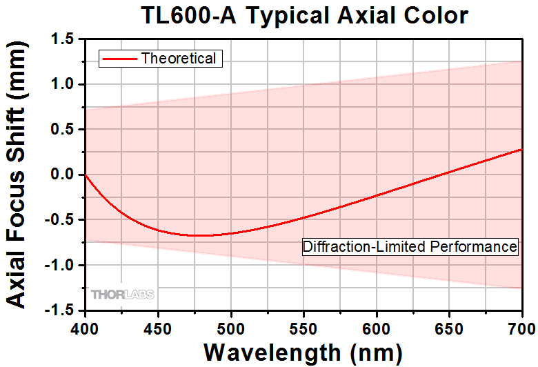 |
 |
 |
 |
 |
 |
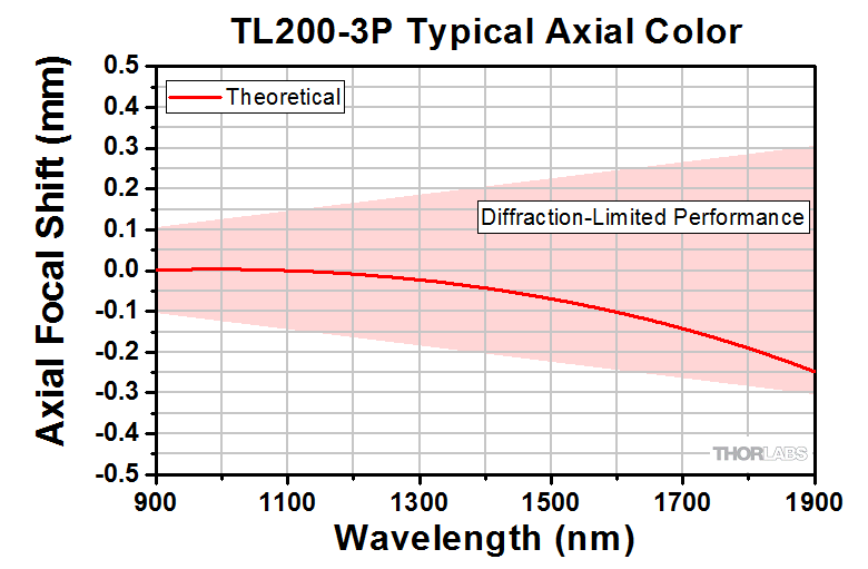 |
|
| RMS Wavefront Error | 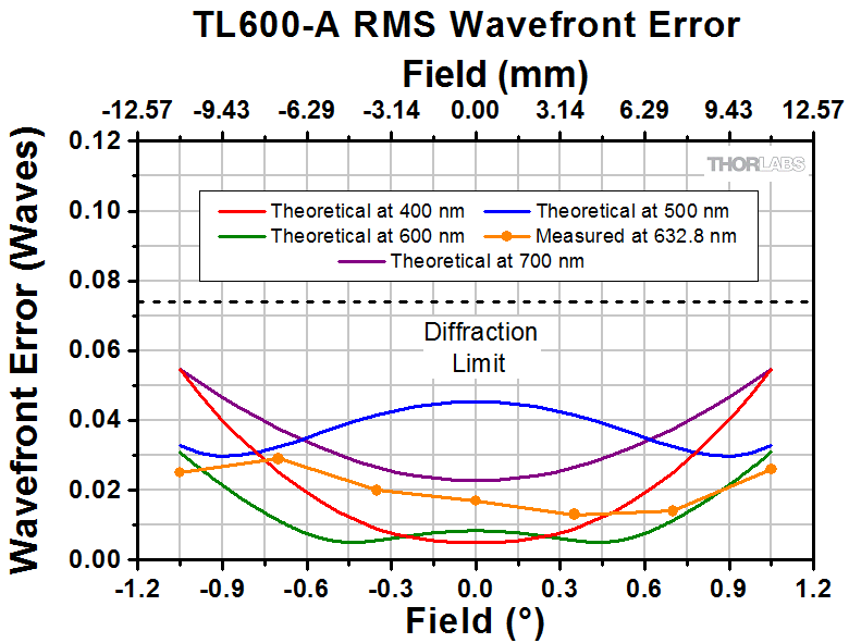 |
 |
 |
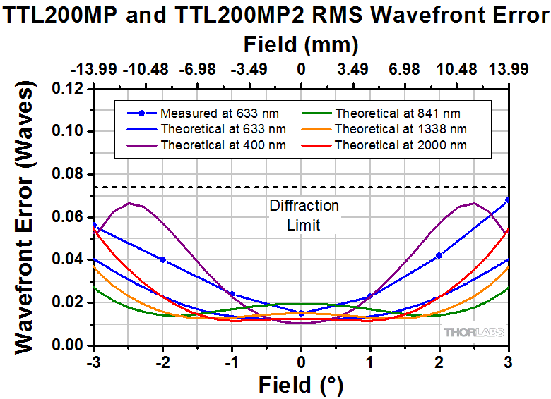 |
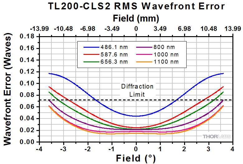 |
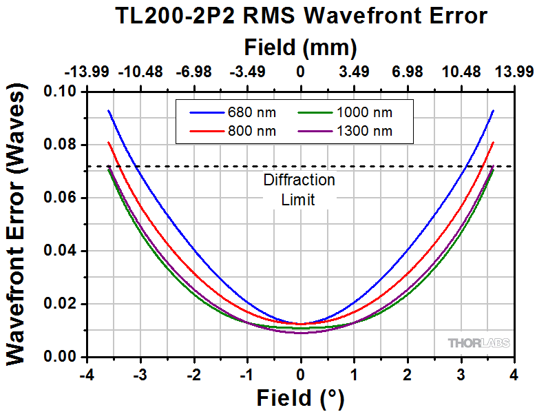 |
 |
|
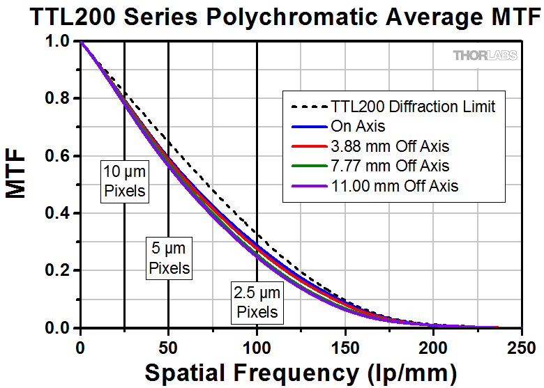
| MTF |
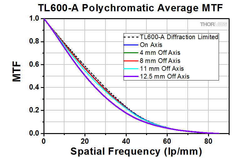 |
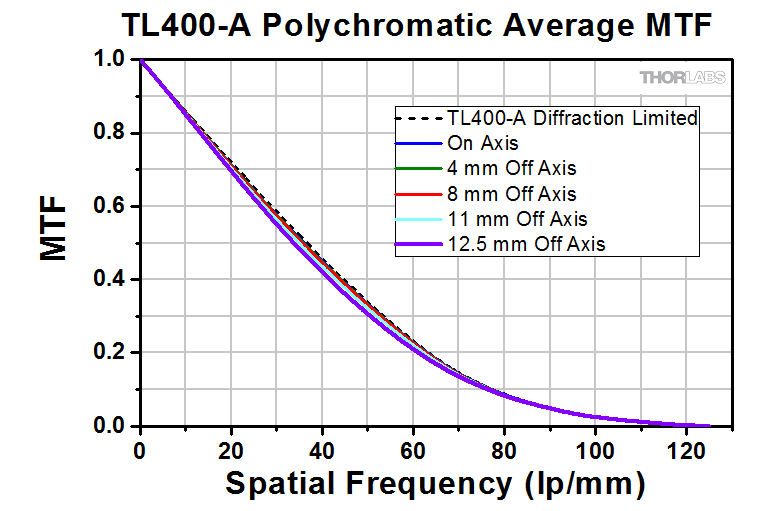 |
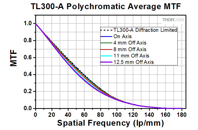 |
 |
 |
 |
 |
|
| Data | Excel Spreadsheet | Excel Spreadsheet | Excel Spreadsheet | Excel Spreadsheet | Excel Spreadsheet | Excel Spreadsheet |
Excel Spreadsheet |
Excel Spreadsheet |
| Zemax Black Box Files | Forward Backward |
Forward Backward |
Forward Backward |
Forward Backward |
Forward Backward |
Forward Backward |
Forward Backward |
Forward Backward |
Click To Enlarge
Figure 2.4 This schematic shows the TTL200MP Tube Lens in a laser scanning configuration with the working distance and pupil distance called out. The working distance corresponds to the distance from the edge of the housing below the engraving to the intermediate image plane. The pupil distance is defined as the distance between the edge of the tube lens housing above the engraving and the entrance pupil of the objective.
| Table 3.1 Parts Lista | |||
|---|---|---|---|
| # | Product Description | Qty. | Photo (Click to Enlarge) |
| 1 | Microscopy Camera | 1 |  |
| 2 | SM1A9 - Adapter with External C-Mount Threads and Internal SM1 Threads | 1 | 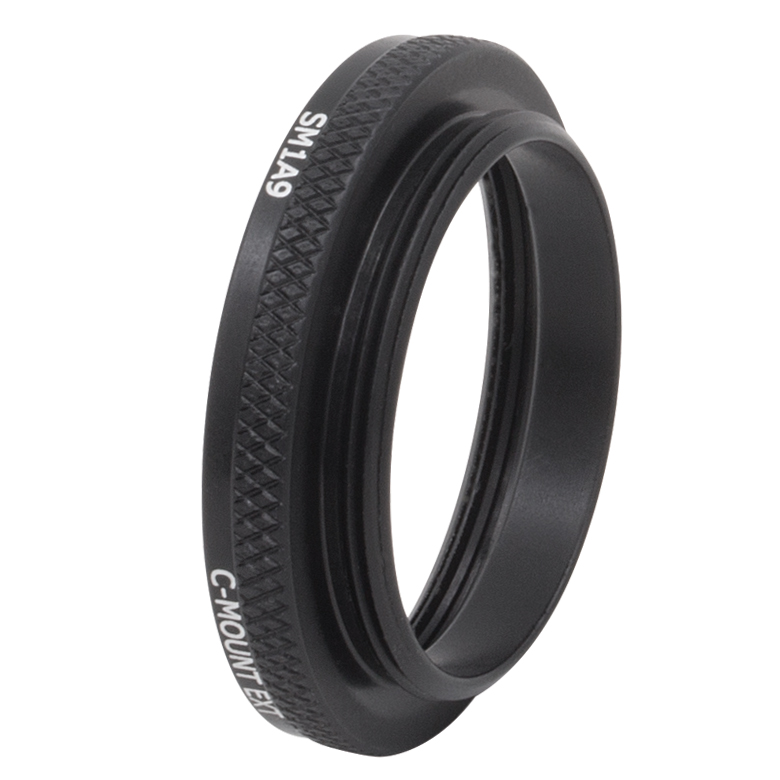 |
| 3 | SM1ZM - Non-Rotating SM1 Zoom Housing for Ø1" Optics | 1 | 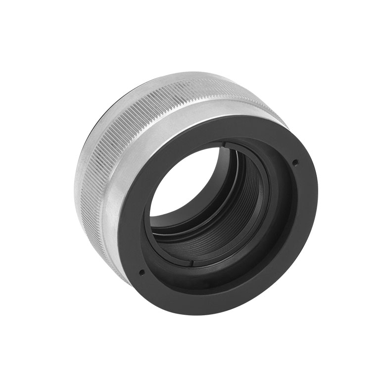 |
| 4 | SM1L03 - SM1 Lens Tube | 1 | 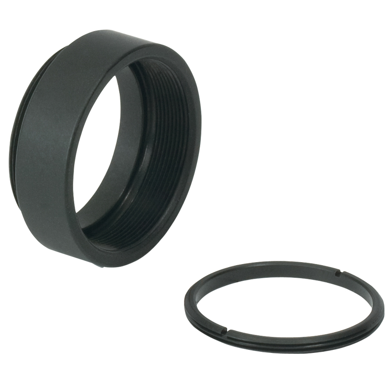 |
| 5 | SM1A2 - Adapter with External SM1 Threads and Internal SM2 Threads | 1 | 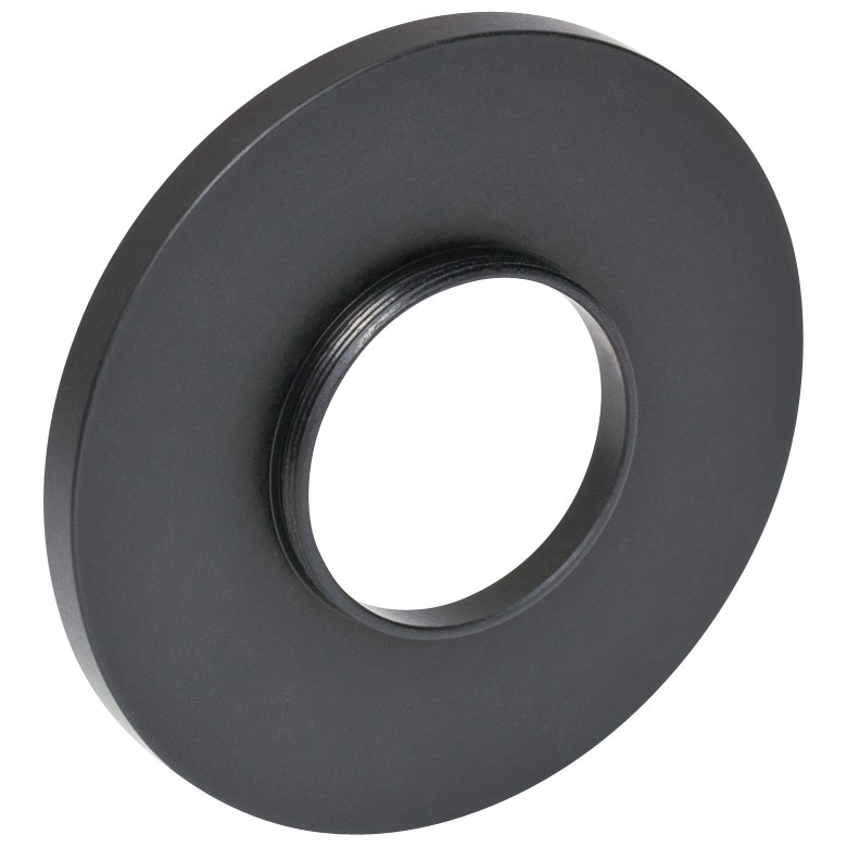 |
| 6 | SM2L39 - Lens Tube Spacer for Tube Lenses |
1 | 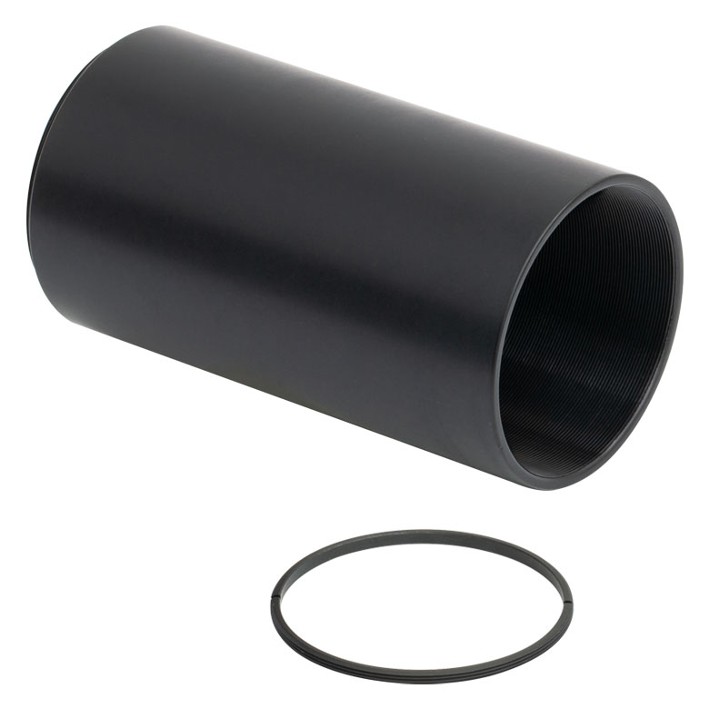 |
| 7 | TTL200-A - Widefield Imaging Tube Lensb | 1 | 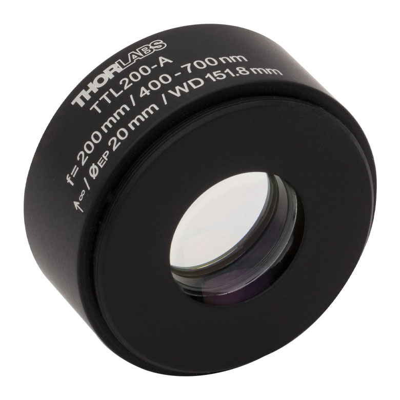 |
| 8 | SM2A59 - Adapter with Male D1N Dovetail and Internal SM2 Threads |
1 | 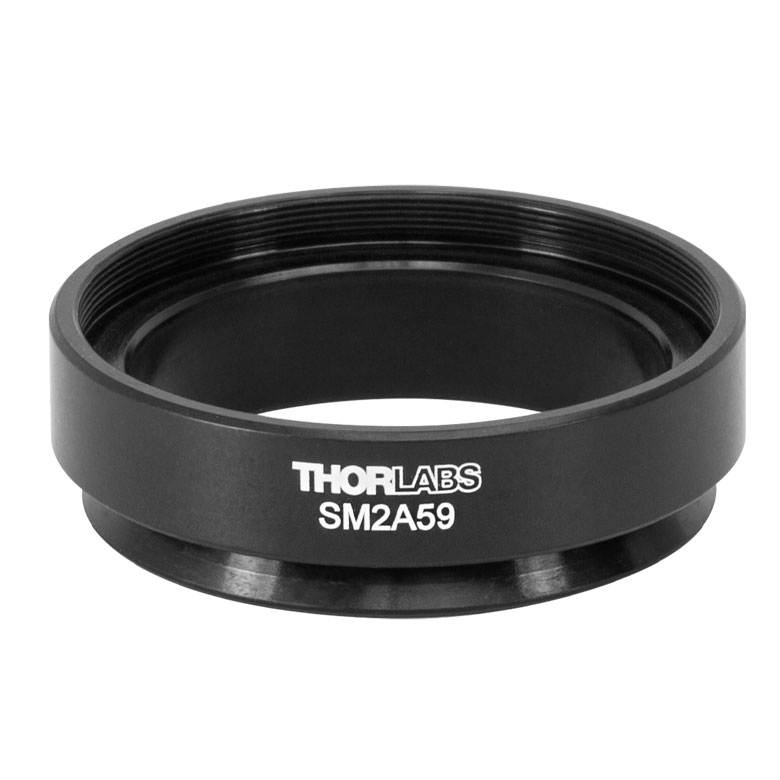 |
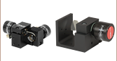
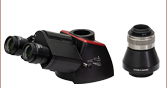
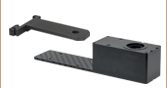
Adjustable C-Mount to SM2 Camera Tube for Widefield and Telecentric Tube Lenses
In the following example, an adjustable C-mount to SM2 camera tube is created to attach a custom widefield imaging assembly to a DIY Cerna microscope. An SM1A9 Adapter (2) is used to connect a C-mount Microscopy Camera (1) to the SM1ZM Zoom Housing (3). An SM1L03 Lens Tube (4) provides extra thread depth to allow full travel of the zoom housing, and an SM1A2 Adapter (5) converts the SM1 threads to SM2 threads. An SM2L39 Lens Tube Spacer* (6) positions the camera at the appropriate working distance from an attached infinity-corrected Tube Lens or Telecentric Tube Lens (7). The SM2A59 Adapter (8) enables the optical assembly to be connected to a DIY Cerna Microscope via a D1N dovetail.
Components used in the configuration pictured in Figure 3.2 are listed in Table 3.1. These parts, along with optomechanical components used to construct a DIY Cerna microscope, are sold separately. Alternate configurations can be built using one of the lens tube spacers offered below with a recommended tube lens.
*The lens tube is designed to position the camera at the image plane of the tube lens when the SM1ZM Zoom Housing is at the center of its adjustment range, allowing for ±1.75 mm travel.

Click to Enlarge
Figure 3.2 An adjustable C-mount to SM2 adapter can be constructed to attach custom widefield imaging assemblies to DIY Cerna microscopes.
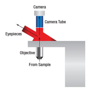
Figure 73A When viewing an image with a camera, the system magnification is the product of the objective and camera tube magnifications. When viewing an image with trinoculars, the system magnification is the product of the objective and eyepiece magnifications.

| Table 73B Focal Lengths by Manufacturer | |
|---|---|
| Manufacturer | Tube Lens Focal Length |
| Leica | f = 200 mm |
| Mitutoyo | f = 200 mm |
| Nikon | f = 200 mm |
| Olympus | f = 180 mm |
| Thorlabs | f = 200 mm |
| Zeiss | f = 165 mm |
Magnification and Sample Area Calculations
Magnification
The magnification of a system is the multiplicative product of the magnification of each optical element in the system. Optical elements that produce magnification include objectives, camera tubes, and trinocular eyepieces, as shown in Figure 73A. It is important to note that the magnification quoted in these products' specifications is usually only valid when all optical elements are made by the same manufacturer. If this is not the case, then the magnification of the system can still be calculated, but an effective objective magnification should be calculated first, as described below.
To adapt the examples shown here to your own microscope, please use our Magnification and FOV Calculator, which is available for download by clicking on the Magnification and FOV Calculator button. Note the calculator is an Excel spreadsheet that uses macros. In order to use the calculator, macros must be enabled. To enable macros, click the "Enable Content" button in the yellow message bar upon opening the file.
Example 1: Camera Magnification
When imaging a sample with a camera, the image is magnified by the objective and the camera tube. If using a 20X Nikon objective and a 0.75X Nikon camera tube, then the image at the camera has 20X × 0.75X = 15X magnification.
Example 2: Trinocular Magnification
When imaging a sample through trinoculars, the image is magnified by the objective and the eyepieces in the trinoculars. If using a 20X Nikon objective and Nikon trinoculars with 10X eyepieces, then the image at the eyepieces has 20X × 10X = 200X magnification. Note that the image at the eyepieces does not pass through the camera tube, as shown by Figure 73A.
Using an Objective with a Microscope from a Different Manufacturer
Magnification is not a fundamental value: it is a derived value, calculated by assuming a specific tube lens focal length. Each microscope manufacturer has adopted a different focal length for their tube lens, as shown by Table 73B. Hence, when combining optical elements from different manufacturers, it is necessary to calculate an effective magnification for the objective, which is then used to calculate the magnification of the system.
The effective magnification of an objective is given by Equation 1:

Here, the Design Magnification is the magnification printed on the objective, fTube Lens in Microscope is the focal length of the tube lens in the microscope you are using, and fDesign Tube Lens of Objective is the tube lens focal length that the objective manufacturer used to calculate the Design Magnification. These focal lengths are given by Table 73B.
Note that Leica, Mitutoyo, Nikon, and Thorlabs use the same tube lens focal length; if combining elements from any of these manufacturers, no conversion is needed. Once the effective objective magnification is calculated, the magnification of the system can be calculated as before.
Example 3: Trinocular Magnification (Different Manufacturers)
When imaging a sample through trinoculars, the image is magnified by the objective and the eyepieces in the trinoculars. This example will use a 20X Olympus objective and Nikon trinoculars with 10X eyepieces.
Following Equation 1 and Table 73B, we calculate the effective magnification of an Olympus objective in a Nikon microscope:
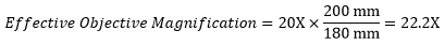
The effective magnification of the Olympus objective is 22.2X and the trinoculars have 10X eyepieces, so the image at the eyepieces has 22.2X × 10X = 222X magnification.
 Figure 73C Sample Area When Imaged on a Camera
Sample Area When Imaged on a Camera
When imaging a sample with a camera, the dimensions of the sample area are determined by the dimensions of the camera sensor and the system magnification, as shown by Equation 2.

The camera sensor dimensions can be obtained from the manufacturer, while the system magnification is the multiplicative product of the objective magnification and the camera tube magnification (see Example 1). If needed, the objective magnification can be adjusted as shown in Example 3.
As the magnification increases, the resolution improves, but the field of view also decreases. The dependence of the field of view on magnification is shown in Figure 73C.
Example 4: Sample Area
The dimensions of the camera sensor in Thorlabs' previous-generation 1501M-USB Scientific Camera are 8.98 mm × 6.71 mm. If this camera is used with the Nikon objective and trinoculars from Example 1, which have a system magnification of 15X, then the image area is:

Sample Area Examples
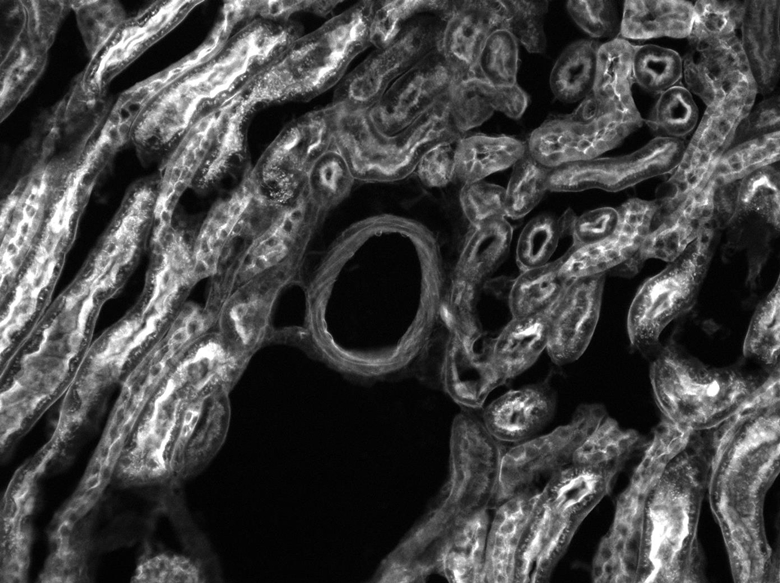
Figures 73D through 73F, images of a mouse kidney, were all acquired using the same objective and the same camera. However, the camera tubes used were different. Figures 73D through 73F demonstrate that decreasing the camera tube magnification enlarges the field of view at the expense of the size of the details in the image.


| Table 5.1 Damage Threshold Specifications | |
|---|---|
| Item # | Pulsed Damage Threshold Specification |
| TTL200-UVB | 5.0 J/cm² (355nm, 10 ns Pulse, 20 Hz, 0.342 mm) |
Damage Threshold Data for Thorlabs' Tube Lens for UV Wavelengths
The specifications in Table 5.1 are measured data for Thorlabs' TTL200-UVB Tube Lens.
Laser Induced Damage Threshold Tutorial
The following is a general overview of how laser induced damage thresholds are measured and how the values may be utilized in determining the appropriateness of an optic for a given application. When choosing optics, it is important to understand the Laser Induced Damage Threshold (LIDT) of the optics being used. The LIDT for an optic greatly depends on the type of laser you are using. Continuous wave (CW) lasers typically cause damage from thermal effects (absorption either in the coating or in the substrate). Pulsed lasers, on the other hand, often strip electrons from the lattice structure of an optic before causing thermal damage. Note that the guideline presented here assumes room temperature operation and optics in new condition (i.e., within scratch-dig spec, surface free of contamination, etc.). Because dust or other particles on the surface of an optic can cause damage at lower thresholds, we recommend keeping surfaces clean and free of debris. For more information on cleaning optics, please see our Optics Cleaning tutorial.
Testing Method
Thorlabs' LIDT testing is done in compliance with ISO/DIS 11254 and ISO 21254 specifications.
First, a low-power/energy beam is directed to the optic under test. The optic is exposed in 10 locations to this laser beam for 30 seconds (CW) or for a number of pulses (pulse repetition frequency specified). After exposure, the optic is examined by a microscope (~100X magnification) for any visible damage. The number of locations that are damaged at a particular power/energy level is recorded. Next, the power/energy is either increased or decreased and the optic is exposed at 10 new locations. This process is repeated until damage is observed. The damage threshold is then assigned to be the highest power/energy that the optic can withstand without causing damage. A histogram such as that shown in Figure 37B represents the testing of one BB1-E02 mirror.
Figure 37A This photograph shows a protected aluminum-coated mirror after LIDT testing. In this particular test, it handled 0.43 J/cm2 (1064 nm, 10 ns pulse, 10 Hz, Ø1.000 mm) before damage.
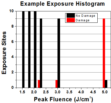
Figure 37B Example Exposure Histogram used to Determine the LIDT of
| Table 37C Example Test Data | |||
|---|---|---|---|
| Fluence | # of Tested Locations | Locations with Damage | Locations Without Damage |
| 1.50 J/cm2 | 10 | 0 | 10 |
| 1.75 J/cm2 | 10 | 0 | 10 |
| 2.00 J/cm2 | 10 | 0 | 10 |
| 2.25 J/cm2 | 10 | 1 | 9 |
| 3.00 J/cm2 | 10 | 1 | 9 |
| 5.00 J/cm2 | 10 | 9 | 1 |
According to the test, the damage threshold of the mirror was 2.00 J/cm2 (532 nm, 10 ns pulse, 10 Hz, Ø0.803 mm). Please keep in mind that these tests are performed on clean optics, as dirt and contamination can significantly lower the damage threshold of a component. While the test results are only representative of one coating run, Thorlabs specifies damage threshold values that account for coating variances.
Continuous Wave and Long-Pulse Lasers
When an optic is damaged by a continuous wave (CW) laser, it is usually due to the melting of the surface as a result of absorbing the laser's energy or damage to the optical coating (antireflection) [1]. Pulsed lasers with pulse lengths longer than 1 µs can be treated as CW lasers for LIDT discussions.
When pulse lengths are between 1 ns and 1 µs, laser-induced damage can occur either because of absorption or a dielectric breakdown (therefore, a user must check both CW and pulsed LIDT). Absorption is either due to an intrinsic property of the optic or due to surface irregularities; thus LIDT values are only valid for optics meeting or exceeding the surface quality specifications given by a manufacturer. While many optics can handle high power CW lasers, cemented (e.g., achromatic doublets) or highly absorptive (e.g., ND filters) optics tend to have lower CW damage thresholds. These lower thresholds are due to absorption or scattering in the cement or metal coating.
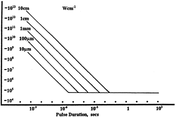
Figure 37D LIDT in linear power density vs. pulse length and spot size. For long pulses to CW, linear power density becomes a constant with spot size. This graph was obtained from [1].
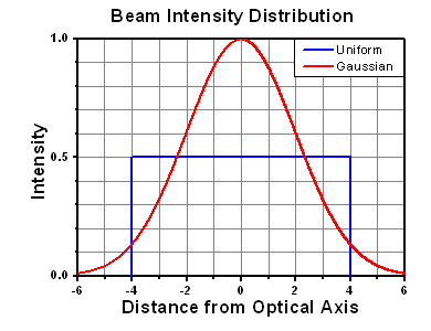
Figure 37E Intensity Distribution of Uniform and Gaussian Beam Profiles
Pulsed lasers with high pulse repetition frequencies (PRF) may behave similarly to CW beams. Unfortunately, this is highly dependent on factors such as absorption and thermal diffusivity, so there is no reliable method for determining when a high PRF laser will damage an optic due to thermal effects. For beams with a high PRF both the average and peak powers must be compared to the equivalent CW power. Additionally, for highly transparent materials, there is little to no drop in the LIDT with increasing PRF.
In order to use the specified CW damage threshold of an optic, it is necessary to know the following:
- Wavelength of your laser
- Beam diameter of your beam (1/e2)
- Approximate intensity profile of your beam (e.g., Gaussian)
- Linear power density of your beam (total power divided by 1/e2 beam diameter)
Thorlabs expresses LIDT for CW lasers as a linear power density measured in W/cm. In this regime, the LIDT given as a linear power density can be applied to any beam diameter; one does not need to compute an adjusted LIDT to adjust for changes in spot size, as demonstrated in Figure 37D. Average linear power density can be calculated using this equation.

This calculation assumes a uniform beam intensity profile. You must now consider hotspots in the beam or other non-uniform intensity profiles and roughly calculate a maximum power density. For reference, a Gaussian beam typically has a maximum power density that is twice that of the uniform beam (see Figure 37E).
Now compare the maximum power density to that which is specified as the LIDT for the optic. If the optic was tested at a wavelength other than your operating wavelength, the damage threshold must be scaled appropriately. A good rule of thumb is that the damage threshold has a linear relationship with wavelength such that as you move to shorter wavelengths, the damage threshold decreases (i.e., a LIDT of 10 W/cm at 1310 nm scales to 5 W/cm at 655 nm):

While this rule of thumb provides a general trend, it is not a quantitative analysis of LIDT vs wavelength. In CW applications, for instance, damage scales more strongly with absorption in the coating and substrate, which does not necessarily scale well with wavelength. While the above procedure provides a good rule of thumb for LIDT values, please contact Tech Support if your wavelength is different from the specified LIDT wavelength. If your power density is less than the adjusted LIDT of the optic, then the optic should work for your application.
Please note that we have a buffer built in between the specified damage thresholds online and the tests which we have done, which accommodates variation between batches. Upon request, we can provide individual test information and a testing certificate. The damage analysis will be carried out on a similar optic (customer's optic will not be damaged). Testing may result in additional costs or lead times. Contact Tech Support for more information.
Pulsed Lasers
As previously stated, pulsed lasers typically induce a different type of damage to the optic than CW lasers. Pulsed lasers often do not heat the optic enough to damage it; instead, pulsed lasers produce strong electric fields capable of inducing dielectric breakdown in the material. Unfortunately, it can be very difficult to compare the LIDT specification of an optic to your laser. There are multiple regimes in which a pulsed laser can damage an optic and this is based on the laser's pulse length. The highlighted columns in Table 37F outline the relevant pulse lengths for our specified LIDT values.
Pulses shorter than 10-9 s cannot be compared to our specified LIDT values with much reliability. In this ultra-short-pulse regime various mechanics, such as multiphoton-avalanche ionization, take over as the predominate damage mechanism [2]. In contrast, pulses between 10-7 s and 10-4 s may cause damage to an optic either because of dielectric breakdown or thermal effects. This means that both CW and pulsed damage thresholds must be compared to the laser beam to determine whether the optic is suitable for your application.
| Table 37F Laser Induced Damage Regimes | ||||
|---|---|---|---|---|
| Pulse Duration | t < 10-9 s | 10-9 < t < 10-7 s | 10-7 < t < 10-4 s | t > 10-4 s |
| Damage Mechanism | Avalanche Ionization | Dielectric Breakdown | Dielectric Breakdown or Thermal | Thermal |
| Relevant Damage Specification | No Comparison (See Above) | Pulsed | Pulsed and CW | CW |
When comparing an LIDT specified for a pulsed laser to your laser, it is essential to know the following:
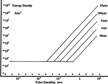
Figure 37G LIDT in energy density vs. pulse length and spot size. For short pulses, energy density becomes a constant with spot size. This graph was obtained from [1].
- Wavelength of your laser
- Energy density of your beam (total energy divided by 1/e2 area)
- Pulse length of your laser
- Pulse repetition frequency (prf) of your laser
- Beam diameter of your laser (1/e2 )
- Approximate intensity profile of your beam (e.g., Gaussian)
The energy density of your beam should be calculated in terms of J/cm2. Figure 37G shows why expressing the LIDT as an energy density provides the best metric for short pulse sources. In this regime, the LIDT given as an energy density can be applied to any beam diameter; one does not need to compute an adjusted LIDT to adjust for changes in spot size. This calculation assumes a uniform beam intensity profile. You must now adjust this energy density to account for hotspots or other nonuniform intensity profiles and roughly calculate a maximum energy density. For reference a Gaussian beam typically has a maximum energy density that is twice that of the 1/e2 beam.
Now compare the maximum energy density to that which is specified as the LIDT for the optic. If the optic was tested at a wavelength other than your operating wavelength, the damage threshold must be scaled appropriately [3]. A good rule of thumb is that the damage threshold has an inverse square root relationship with wavelength such that as you move to shorter wavelengths, the damage threshold decreases (i.e., a LIDT of 1 J/cm2 at 1064 nm scales to 0.7 J/cm2 at 532 nm):

You now have a wavelength-adjusted energy density, which you will use in the following step.
Beam diameter is also important to know when comparing damage thresholds. While the LIDT, when expressed in units of J/cm², scales independently of spot size; large beam sizes are more likely to illuminate a larger number of defects which can lead to greater variances in the LIDT [4]. For data presented here, a <1 mm beam size was used to measure the LIDT. For beams sizes greater than 5 mm, the LIDT (J/cm2) will not scale independently of beam diameter due to the larger size beam exposing more defects.
The pulse length must now be compensated for. The longer the pulse duration, the more energy the optic can handle. For pulse widths between 1 - 100 ns, an approximation is as follows:

Use this formula to calculate the Adjusted LIDT for an optic based on your pulse length. If your maximum energy density is less than this adjusted LIDT maximum energy density, then the optic should be suitable for your application. Keep in mind that this calculation is only used for pulses between 10-9 s and 10-7 s. For pulses between 10-7 s and 10-4 s, the CW LIDT must also be checked before deeming the optic appropriate for your application.
Please note that we have a buffer built in between the specified damage thresholds online and the tests which we have done, which accommodates variation between batches. Upon request, we can provide individual test information and a testing certificate. Contact Tech Support for more information.
[1] R. M. Wood, Optics and Laser Tech. 29, 517 (1998).
[2] Roger M. Wood, Laser-Induced Damage of Optical Materials (Institute of Physics Publishing, Philadelphia, PA, 2003).
[3] C. W. Carr et al., Phys. Rev. Lett. 91, 127402 (2003).
[4] N. Bloembergen, Appl. Opt. 12, 661 (1973).
| Posted Comments: | |
Vladimir Zenin
(posted 2025-04-03 09:46:52.59) Hi, I was surprised to see the range of TTL200-S8 lens. I believe, this is the only lens in your assortment which covers both visible (400-800) and true near-infrared range (800-1700). Can you produce similar lenses of different 'standard' focal lengths (e.g., 50, 100, 150 mm) and show them in 'achromatic lenses' menu?
Also, another impressive part here is your super-broadband Single-Layer MgF2 Coating (again, I haven't seen any other element in your shop with such coating). Why don't you make other optical elements (e.g., lenses) with this coating? Hao Tang
(posted 2024-12-26 17:41:31.453) Hello, when I simulate with Zemax and actually set up the optical path, I encountered the following issue: The pupil distance of the TTL200MP does not seem to be 228 mm with the SL50-2P2 scan lens. The distance from the galvanometer mirror to the first mechanical surface of the SL is 37.8 mm. The distance from the last mechanical surface of the SL to the first mechanical surface of the TL is 177.8mm, and the distance from the last mechanical surface of the TL to the conjugate plane of the galvanometer mirror is approximately 151 mm (results from both simulation and actual optical path), which is much less than 228mm. Why is this happening? EGies
(posted 2025-01-10 03:18:18.0) Thank you for contacting Thorlabs. When you set up the system in Zemax, you will want to use the Zemax (ZAR) - Reverse Black Box for the TTL200MP. This file can be downloaded directly from the web: https://www.thorlabs.com/_sd.cfm?fileName=TTN111297-S04.zar&partNumber=TTL200MP. When you use this file, you get the correct conjugate or pupil distance of 228mm. If you accidentally use the Forward Black Box for the TTL200MP, you will get the incorrect 151mm conjugate distance which you have reported. I have reached out to you directly regarding this. Further troubleshooting requests can be emailed directly to techsupport@thorlabs.com. link yuan
(posted 2024-05-30 02:11:36.043) I noticed that the TTL-200 has a focal length tolerance of 200mm ± 1%, but the working distance indicated on the drawing is 146.8mm. Is the working distance of 146.8mm reliable for actual installation? Will the optimal working distance deviate from 146.8mm?
Thanks. ksosnowski
(posted 2024-05-30 12:15:39.0) Hello Link, thanks for reaching out to Thorlabs. The tolerances on the mechanical lens tube and assembly are quite tight and the +/-1% focal length tolerance of the 200mm EFL lens itself is what contributes primarily to effective tolerance in the working distance. Using wavelengths past the design band would require a different working distance as well for optimal focus. I have reached out directly to discuss your application in further detail. user
(posted 2024-02-01 09:49:34.367) I am interested in using the TTL200 or TTL200-MP for ultrafast microscopy applications. Do you have estimates of the group delay dispersion of these lenses in the visible and near infrared spsctral regions? I don't have Zemax and can't calculate these values from the black box files. Thanks. cdolbashian
(posted 2024-02-02 09:41:40.0) Thank you for reaching out to us with this inquiry. I have sent you some simulated data regarding the tube lens requested. Additionally I have followed up regarding additional information which you might require. Francesco Sacco
(posted 2023-11-25 16:54:03.81) I have macro photography equipment developed by you consisting of
Mytutoyo Plan Apo 10X 0.28 ∞
Mitutoyo Plan Apo 5X 0.14 ∞
AC254-060-A - f=60.0 mm, achromatic doublet Ø1",
AC254-100-A - f=100.0 mm, achromatic doublet Ø1",
AC254-150-A - f=150.0 mm, achromatic doublet Ø1",
AC254-200-A - f=200.0 mm, achromatic doublet Ø1",
AC254-250-A - f=250.0 mm, achromatic doublet Ø1",
Mount on SM1L 05.
With Plan Apo 10x I get the best results with 150 mm, less so with 200 mm.
I wanted to know which of the TTL200 (Lire, 200, 200-A, 200-SB, 200-B, ?) could be used as an alternative to my current AC254-200-A, maintaining the Wd of the Mitutoios and whether it would significantly improve the quality of the images .
If so, please send me a quote for the tube lens complete with any adapters.
Thank you. cdolbashian
(posted 2023-12-15 03:55:39.0) Thank you for reaching out to us with this application inquiry. I have reached out to you directly and we have discussed this extensively. We have discussed they requirements and spacing needed to achieve optimal spacing for your macrophotography setup. Charles Chen
(posted 2023-11-16 13:40:24.863) Dear Sir,
We would like to ask if the TTL200-A can be used with a CO2 singlet lens (ex. ZnSe F=60mm lens) instead of an objective lens? Thank you! user
(posted 2023-11-06 11:23:48.04) what are the tubes to connect a TTL180-A to a C-mount camera and TTL180-A to a MY10X-803 objective? cdolbashian
(posted 2023-12-13 04:50:22.0) Thank you for reaching out to us with this inquiry. Because the working distance and pupil distance for the tube lens and objective are fairly specific, it is important to have appropriate spacing which will result in optimal image clarity. I would recommend using some adjustable tube lenses and/or cage elements. I have reached out to you directly to point you toward such elements. Suk Hyun Kim
(posted 2023-07-28 16:00:06.843) Hi Thorlabs, I would Like to construct micrometer-size PL scanning system out of fast steering mirror. The Laser I want to use is 266nm UV laser, so I have to purchase scan lens and tube lens with UV compatibility.
However, in that wavelength range, the only Thorlabs' tube lens was TTL200-UVB, and I could not find any Thorlabs scan lens.
Moreover the Thorlabs' tube lens TTL200-UVB is for Widefield Imaging. Can I use this for Laser Scanning as well? If not, what is the difference between the tube lens for Widefield Imaging and the tube lens for Laser Scanning? srydberg
(posted 2023-08-14 09:21:51.0) Thank you for your question! We have contacted you directly to discuss your application. Ryan (himself)
(posted 2023-06-14 15:52:34.737) Hi Thorlabs, to better appreciate these, how many lens elements might a tube lens such as TTL100-A have inside it? cdolbashian
(posted 2023-06-20 03:13:57.0) Thank you for your appreciation of these tube lenses! The TTL100-A has a pair of doublets within the housing, yielding a total of four individual lens elements. Siman Lim
(posted 2023-02-02 16:00:08.66) Hi.
I want to know ITL200 Recommend distance(Locating flange of objective) and Image plane distance. cdolbashian
(posted 2023-06-14 01:44:11.0) Thank you for reaching out to us with this inquiry. The pupil distance and working distance are described within the "specs" tab above! I have reached out to you directly to share these values with you. Greg Hn
(posted 2022-06-10 16:48:11.467) Hi, could you please share CodeV files in addition to the Zemax files ? Thanks jdelia
(posted 2022-06-10 03:22:00.0) Thank you for contacting Thorlabs. Unfortunately, we do not offer CodeV files for our parts. We apologize for the inconvenience. Chandrasekhar Mutyala
(posted 2022-04-13 10:01:30.297) Hi, I have a query on the sample area calculation. The sample area calculation, decreasing with increase of system magnification, represents the dimensions of the image we visualize on the camera or the field of view with image size equal to the camera sensor dimensions. cdolbashian
(posted 2022-04-20 04:38:19.0) Thank you for reaching out to us with your inquiry. The wording of this inquiry leaves a bit of room for misunderstanding. In order to clarify and understand your inquiry fully, I have reached out to you directly to discuss the topic of FOV and magnification with you. Bryan Bosworth
(posted 2021-12-23 20:45:14.957) I received a TTL200MP2 this week (I believe the order code was NUW1245358). It arrived with kapton tape stuck onto the two sides of the lens (inside dusty paper padding). This is very disappointing. The TTL200 I ordered some time ago came with SM2 covers on both sides that kept the lens ready to use without sticky tape on the coated glass surfaces. cdolbashian
(posted 2022-01-05 05:03:13.0) Thank you for reaching out to us Bryan. As you assessed, there should have been endcaps on both ends of your tube lens. I have contacted you to rectify this. Glenn Chan
(posted 2021-07-26 12:20:28.67) Hi,
We are considering to use this Tube lens in our system. However, we noticed a mismatch between the listed Spec and CAD. The overall length Spec listed is 33.5mm, but the CAD and PDF shows 31.1mm. I assume the CAD is right, please confirm.
Thanks,
Glenn YLohia
(posted 2021-07-30 04:08:15.0) Hello Glenn, thank you for your feedback and bringing this to our attention! You are correct-- the TTL1180-A housing is indeed actually 31.1 mm. While double-checking that, I also noticed that the TTL100-A is 33.5 mm, not 31.1 mm as shown in the specs table as of this post (we must have accidentally swapped the dimension for the two at the time of listing these parts on the web). We will correct this information on the website as soon as possible. Alex Schmitz
(posted 2021-04-27 14:58:26.963) Hi Team,
as I understood from other feedback below, the difference between working distance and focal length is that the latter is given from an unknown principle plane of the lens.
However, for the TTL165-A, the difference is about 5cm but the lens and mount does look nothing close to that.
In principle: Is the image plane for tube lenses supposed to coincide with the focal plane?
Thanks! cdolbashian
(posted 2021-05-06 09:28:55.0) Thank you for reaching out to us at ThorLabs! To answer your last question first, yes. For a single lens system the WD and the focal length would only differ by a distance on the order of the thickness of the lens. In this case, however, the tube lenses are not single element optics but actually contain multiple lenses, causing the principal plane of the lens system to lie outside of the physical optics themselves. Rather than having to locate the exact position of this external plane, we use WD as an analogous measurement to focal length because it is measured from the housing of the optic itself. Owen Sun
(posted 2021-03-25 14:18:20.09) Could you let me know the magnification of TTL200 in your product line? I could not find the relevant info. YLohia
(posted 2021-03-25 03:39:16.0) Hello, the magnification is dependent on the objective lens paired with the TTL200 and is not entirely governed by the tube lens. Please see the "Magnification & FOV" tab for more information. user
(posted 2021-03-23 11:02:58.01) Could you, please, comment why on your MTF graphs there is such a big difference in support range for TTL200MP vs TL200-2P2 / TL200-3P. The first lens looks to support frequencies up to ~220 lp/mm, while the other two support barely half of that. NA of the lenses looks similar, so I don't understand where such big difference comes from. Thank you! YLohia
(posted 2021-04-12 04:47:13.0) The MTF curves shown on the web site are polychromatic plots, so they take all the wavelengths and do the MTF calculation. The TL200MP is designed for a wavelength range of 400-2000nm, while the TL200-3P is designed for 900-1900 nm. The MTF scales with the inverse of the wavelength so the 3P will have roughly twice the cutoff frequency compared to the TL200MP. Thomas Dzelzainis
(posted 2021-03-18 12:48:13.96) Hi,
I am wondering if it possible to get this optic either uncoated, or coated with your 'B' anti-reflection coating for 650-1050 nm?
Many thanks,
Tom. YLohia
(posted 2021-03-18 02:13:37.0) Hello Tom, thank you for contacting Thorlabs. Custom optics can be requested by emailing techsupport.uk@thorlabs.com. We will discuss the possibility of offering this customization directly. user
(posted 2021-03-03 12:45:34.393) Are the track length of the Zemax black box files specified from first to last lens surface or from the front and back side of the housing? I am especially interested about the TTL200-A and the TTL-200MP. YLohia
(posted 2021-03-05 10:32:39.0) Hello, the track length is specified from the front and back side of the housing. Volker Lutter
(posted 2021-03-03 17:28:57.087) From your catalog, it is not clear, what exactly is the working distance. What is the reference layer? For Objectives it is usually the most top layer of the objective. Or is it the contact surface at the end of the thread?
Greatings from Germany
Dr. Volker Lutter asundararaj
(posted 2021-03-03 02:44:45.0) Thank you for contacting Thorlabs. The working distance corresponds to the distance from the top surface of the housing to the image plane. A schematic showing the working distance is in the spec tab below the specs table. Christian Tardif
(posted 2020-06-08 13:40:37.867) Hello
I'm wondering if these lens will emit fluorescence when intense 450nm light will pass through it. We would like to use it as part of a bi-telecentric system when fluorescence will pass back by the same lense and lenses fluoresce could make a problem. I'm asking it because we experienced this problem with another lense system.
Thank you in advance. nbayconich
(posted 2020-07-07 03:27:29.0) Thank you for contacting Thorlabs. At the moment we do not have fluorescence data for these tube lenses. I will reach out to you directly to discuss your application. Markus Vartiainen
(posted 2020-04-08 08:07:46.827) Are you absolutely sure that the Zemax *Forward* and *Reverse* Black Box models for this tube lens are correct? I don't see any difference in traced rays whether I have the Forward or Reverse model. I would very much like to ensure that I'm getting correct results in my simulation. YLohia
(posted 2020-04-30 09:06:26.0) Thank you for contacting Thorlabs. Yes, we have triple-checked the Zemax files for the TTL200-S8 and they are correct. user
(posted 2020-03-26 07:22:00.19) Could you please clarify the calculation of the pupil distance? Based on the given entrance pupil (20 mm), image field size (22 mm), focal length (200 mm), and maximum pupil distance (170 mm) I get a tube lens entrance aperture of ([170*22]/200 + 20 =) 38.7 mm, which seems to be too large. asundararaj
(posted 2020-04-16 03:58:22.0) Thank you for contacting Thorlabs. The pupil position on the TTL200-A can vary from 100 - 170 mm. If you would like to use two tube lenses as a relay, the position of the telecentric pupil position is somewhere around 248 mm. Since the TTL200-A is not telecentric there will be significant vignetting. A better choice for a relay would be the TTL200MP since it is designed to be telecentric, consequently you wouldn’t get any vignetting by using two of them as a 1X relay. If you would like to continue to discuss this further, please email us at techsupport@thorlabs.com Nick Anthony
(posted 2020-02-11 11:11:45.983) I was recommended to use two TTL200 as relay lenses to create "infinity space" outside the body of a Nikon microscope for the insertion of a Kurios VB-1 LCTF and other optical components before the camera. While the working distance on one side of the lens is 148mm I was surprised to find that the pupil plane is ~290mm on the other side of the lens. This means that the total length of my relay is roughly 2*(148 + 290)= 876mm which is too long to fit on the table. Is there a better set of lenses I can use to relay a diffraction limited image from the camera port of a Nikon microscope? nbayconich
(posted 2020-03-03 03:18:12.0) Thank you for your feedback, an achromatic doublet lens with a shorter working distance could potentially be used such as the ones below.
https://www.thorlabs.de/newgrouppage9.cfm?objectgroup_id=120
These lenses would not have the same performance as our diffraction limited tube lenses but may be more suitable to reduce the working distance of your optical system. user
(posted 2019-10-28 07:15:26.667) Hello
I am considering using a TL200-CLS2 scan lens with the SL50-CLS2 tube lens for a Leica based confocal setup, using high NA Leica glycerol and oil objectives.
Do you have any information regarding the compatibility of these lenses with Leica objectives for high resolution imaging?
Thank you nbayconich
(posted 2019-10-29 04:22:14.0) Thank you for contacting Thorlabs. Our tube lenses are corrected for chromatic aberrations independently of the selected objective lens, so the TL200-CLS2 can be paired with any Leica objective lens designed to be used with 200mm focal length tube lens. Please note that the magnification will change if an objective lens designed for a different tube lens EFL other than 200mm is used with the TL200-CLS2. Pavel Fedorov
(posted 2019-09-26 03:02:16.57) Hello! I want to buy Thorlabs ITL200 from you, can you send the order to Russia by regular mail? NOT FedEx, UPS I do not need these types of delivery. YLohia
(posted 2019-09-26 10:28:05.0) Hello, thank you for contacting Thorlabs. Our sales team (sales@thorlabs.com) will reach out to you directly to discuss your shipping options. Tobias Feger
(posted 2019-09-03 03:06:10.793) Hi, It would be great if you could provide the TTL180 and TTL165 tube lenses with AB BBAR coating such that those lenses can be used over a wider wavelength range, potentially up to 1.1 micron, and in a more compact housing (e.g. M38 x 0.5). Thank you! YLohia
(posted 2019-09-03 03:15:39.0) Hello, thank you for your feedback! We will take your input into consideration in the design of a future product. user
(posted 2019-07-11 06:39:01.127) Hello
The specs of this lens (TTL200-MP) and the TL200-CLS2 lens are nearly identical, yet the price difference is very big. If there is one, what is the advantage of the TL200-CLS2 in terms of optical performance? Are there any differences between the two lenses with respect to chromatic shifts that would impact 2-color imaging differently.
Thank you YLohia
(posted 2019-07-16 09:08:19.0) Hello, thank you for contacting Thorlabs. The TL200-CLS2 offers superior transmission in the operating range along with a significantly better axial color (focal length shift) performance. Please see the "Specs" tab for more information. alex.maclean
(posted 2018-11-15 15:38:36.56) I am trying to model and then build a confocal microscope using Thorlabs parts. I am trying to select parts that I can model in Zemax and I appreciate that the design of your lenses is a trade secret, but the black box files do not convert into non-sequential models that I can use. It would be very useful if you could provide non-sequential files as well as the sequential ones or if there is some way to convert them that I am missing that would be even better.
Many thanks,
Alex Maclean nbayconich
(posted 2018-11-29 10:44:07.0) Thank you for contacting Thorlabs. At the moment zemax does not provide a method to convert a sequential block box model into a non-sequential mode. hinoki.kuaimu
(posted 2018-08-02 17:38:06.747) Besides a change in magnification ratio, what is the influence on the image of a reduced working distance? I've used your TL2X-SAP super apochromatic lens with a TTL200 working distance of 73mm and got qualitatively sharp images with no noticeable defect (images of live insects in the wild, I have yet to perform experiments with an appropriate test target to better assess the potential image degradation with shorter tube lens working distances). YLohia
(posted 2018-08-27 02:50:51.0) Hello, thank you for contacting Thorlabs. There are a few considerations when operating at a reduced working distance. As you pointed out, the magnification will change. The system will also produce more aberration/distortion. These two are the side effects with the most noticeable impact. Furthermore, the NA and FOV will also change. wenzel.jakob
(posted 2017-11-30 01:10:38.513) Hi,
your webpage states: "Please note that using a standard tube lens in a scanning configuration will limit the unvignetted field size, since the tube lens must be placed at the telecentric pupil distance from the objective."
Could you clarify how this telecentric pupil distance is determined? The "Specs" tab lacks information on this distance values, e.g. for ITL200.
Thanks! tfrisch
(posted 2018-03-03 12:28:18.0) Hello, thank you for contacting Thorlabs. Telecentric Pupil Distance is roughly the focal length when the lens is used in the reverse direction. While using a lens in the reverse direction is not recommended, knowing this value can be useful in modeling a system. A lens is considered telecentric when the focal length falls at the aperture stop of a system, and this places your entrance or exit pupil at infinity (for object or image space telecentricity respectively). The determination of these distances is best done in the modeling software we use to design the lenses (Zemax). We provide black box Zemax files for many of our lens systems as the full prescription is considered proprietary. As for the ITL200, we do not have exact values for many of the specs, but I will reach out to you directly about how to compare against a similar lens, like TTL200. h.wu
(posted 2017-10-03 19:57:11.14) TTL200 series has a (back) working distance of 148 mm. Could you provide the (front) working distance of TTL200-B? We would like to know the case that a collimated beam is incident from its image plane toward the objective. Thanks. tfrisch
(posted 2017-12-06 11:24:22.0) Hello, thank you for contacting Thorlabs. These lenses are designed for infinite conjugate use, so you need to be careful if using it in reverse with the infinity space on the opposite side of the lens. Most notably, there will be more spherical aberration as well as vignetting. However, the distance from the opposite focal plane to the housing will be 238.1mm. I will reach out to you to discuss your application further. shawncasey
(posted 2017-08-10 18:27:27.11) Is the TTL180 actually an Olympus tube lens or a generic equivalent? We have our own tube lens and were wondering if the mount is the same? If so could we purchase it without the lens, so we can more easily adapt our lens to SM2? tfrisch
(posted 2017-08-16 06:24:40.0) Hello, thank you for contacting Thorlabs. TTL180-A was designed here at Thorlabs. The mount is not just an adapter for a different complete tube lens, it holds the component lenses and spacers, so a different lens would likely not fit. I will reach out to you about adapting your lens to SM2. h.wu
(posted 2017-04-23 14:22:55.03) Hi,
I was very confused the diagram (tube lens schematic) and the description shown in the link the that lenses with external SM2 threads (TTL200-B and TTL200-S8) should be oriented the same as in the diagram. https://www.thorlabs.com/newgrouppage9.cfm?objectgroup_id=5834
I think that the arrow of TTL200-B in the tube lens schematic should point to the objective (pupil distance) rather than to the image plane because the diagram (tube and scan lens schematic) of the TL200-2P2 shows its arrow pointing to the objective (pupil distance).
There is a sentence for TL200-2P2 tube lens in your website.
The tube lenses are engraved with an arrow next to an infinity symbol (∞) to indicate which side of the lens should face the objective (infinity space).
Thanks tcampbell
(posted 2017-04-24 11:17:37.0) Response from Tim at Thorlabs: thank you for your feedback. You are correct, the arrow next to the infinity symbol on the tube lens should point toward the objective. We have updated the diagram accordingly. user
(posted 2017-02-15 11:04:34.723) How do we choose TTL or ITL200? Confusion is that there is no comparison ITL and TTL, and ITL has less information in a specification chart. What is pros and Cons we choose ITL200? tfrisch
(posted 2017-02-17 02:04:09.0) Hello, thank you for contacting Thorlabs. Nikon manufactures the ITL200, so we do not have a full design comparison against our own TTL200. If you would like to discuss further, please email us at TechSupport@thorlabs.com hsieh-fu.tsai
(posted 2016-12-08 23:50:45.78) I am interested to build an microscope with this tube lens.
However, I wonder how mounting can be done to connect the tube lens to a c-mount camera?
Thank you. tfrisch
(posted 2016-12-19 02:21:24.0) Hello, thank you for contacting Thorlabs. We have an application note on assembling a simple microscope as well as our Do It Yourself (DIY) Cerna series microscope components. I will contact you directly about options.
Application note: https://www.thorlabs.com/newgrouppage9.cfm?objectgroup_id=5835&tabname=Application
Cerna series: https://www.thorlabs.com/navigation.cfm?guide_ID=2371 y.tian
(posted 2016-10-11 05:29:18.583) Hello,
If I can also use ITL200 in an IR system. Because TL200 2P2 is too expensive that already beyond the budget. What makes such huge price difference?Thanks. jlow
(posted 2016-10-21 04:24:11.0) Response from Jeremy at Thorlabs: The TL200-2P2 has been optimized for scanning application and it is designed for a wider wavelength range than the ITL200. While it can work for some scanning applications (e.g. if your scan angle is small), it’s not ideal solution. I will contact you directly to discuss further about this xliay
(posted 2016-09-27 13:13:22.31) Nowadays we are using LSM04-BB as the scan lens and AC508-250-B as the tube lens combination. However, in our stimulated Raman scattering (SRS) microscopy, we found that the Pump beam (780~960 nm) was not perfectly overlapped with the Stokes beam (1031 nm) when the scanning field of view is larger than 60 um using 40X objective. This phenomenon is possibly introduced by the lateral chromatic aberration of our scan relay system because we observed that the FOV is better when using 900 nm than 800 nm. So are there any recommendations of NIR scan relay system from Thorlabs to meet our requirement? jlow
(posted 2016-10-03 05:08:20.0) Response from Jeremy at Thorlabs: I will contact you directly to discuss about this. andreas.groeschl
(posted 2016-06-06 14:15:41.05) Dear ladies and gentleman,
may question is, why is the Working Distance much less than the focal lenght?
Best regards
Andreas besembeson
(posted 2016-06-08 09:23:25.0) Response from Bweh at Thorlabs USA: The focal length is relative to a principal plane of the actual lens element which is inside the housing while the working distance is relative to the external housing edge. ludoangot
(posted 2016-03-17 14:00:38.693) I also need the ITL200 front focal length, has Nikon provided this information? If not, would it be possible you measure it? Ideally a tick lens model of the ITL200 would be much welcome. besembeson
(posted 2016-03-17 02:59:42.0) Response from Bweh at Thorlabs USA: Unfortunately Nikon doesn't provide this information. jesmondhong
(posted 2016-03-11 03:32:34.817) Hi, if i have a lens attached to the camera sensor, should I keep a 148mm from the end of the ITL200 to the front mount of the lens attached to the camera? besembeson
(posted 2016-03-11 11:20:51.0) Response from Bweh at Thorlabs USA: The ITL200 is your imaging lens so the 148mm should be to the camera sensor. If you have an additional relay lens (which is not typical), then that distance should correspond to the object plane of your relay lens. pedroalves.dct
(posted 2016-02-19 09:33:28.01) Hello,
my purpose is photography.
My setup:
- Olympus OMd-Em5II camera;
- Mitutoyo Mplan 5 and 10x lens.
Between the lens and the camera I've an iris diaphragm (from thorlabs) and a raynox dcr250 as tube lens. Between the raynox and the camera I've a extension bellows at 100mm.
Well, I'm not happy with the setup and I would like to try the ITL200 instead of the raynox.
I need some advices about the distances between the mitutoyo and the ITL200 and the ITL and the camera sensor?
Many thanks in advance.
Sincerely,
Pedro Alves besembeson
(posted 2016-03-03 04:05:05.0) Response from Bweh at Thorlabs USA: The camera sensor should be about 148mm from the end of the ITL200 and the front of the ITL200 can be between 70-170mm from the end of the objective. gtn75
(posted 2015-11-19 19:55:17.567) I want to know where are the principal planes of the ITL200. besembeson
(posted 2015-11-20 02:30:45.0) Response from Bweh at Thorlabs USA: The back focal length is 148mm. We don't have information on the front focal length. I will contact you if Nikon can provide this. jghimcm
(posted 2015-10-27 14:30:16.873) Can this tube lens used with a Leica Infinity-corrected objective? Thanks! besembeson
(posted 2015-11-05 10:19:41.0) Response from Shawn at Thorlabs China: It depends on your application. If it involves a monochromatic source, then it should be okay but it may not be very suitable if you have to account for chromatic aberration. This is because Leica (and Zeiss) microscopes have color correction inside their tube lens. They don't correct for chromatic aberrations in the objective. Nikon (and Olympus) have color correction in the their microscope objectives, not in the tube lens. a.bruni
(posted 2015-04-14 08:59:22.95) dear All,
I need a thecnical contact to explane my castom problem.
Andrea jlow
(posted 2015-04-15 04:03:15.0) Response from Jeremy at Thorlabs: You can contact us at techsupport@thorlabs.com to discuss about your application. user
(posted 2015-01-29 19:02:32.153) The focal length is 148mm from the mounting side, what is it from the other side? jlow
(posted 2015-01-29 02:13:12.0) Response from Jeremy at Thorlabs: The orientation, distances, and dimension of the tube lens are located in the drawing under "Specs" tab. I am not sure I fully understand your question. Since you did not leave any contact information, can you contact us at techsupport@thorlabs.com to discuss about this further please? user
(posted 2015-01-05 11:30:45.733) Could you please specify the focal length tolerance on this lens system? cdaly
(posted 2015-01-09 01:37:27.0) Response from Chris at Thorlabs: The specified tolerance is +/-1%, but it is realistic to expect it to be closer to +/-0.5%. ieivanov
(posted 2014-07-29 19:00:57.11) You should offer a 2 inch lens tube with internal SM2 threads on one end and set screws for attaching a C-mount on the other end. The lens tube should be the appropriate length, such that when used with the ITL200 lens and the SM2A20 adapter, the sensor of a camera mounted at the C-mount would be the correct focal distance away from the ITL200 lens. cdaly
(posted 2014-08-07 02:53:02.0) Response from Chris at Thorlabs: Thank you for your suggestion. We will discuss the idea internally and it may be something you see offered as a standard product in the future. We welcome any product ideas which you think would serve to help make our products more useful in your applications. ikky.shura
(posted 2014-06-25 19:07:09.623) Hi,
I purchased this ITL200 lens and it seems to me that the front focal length is more like 250mm by trying to image an obect located at > 10x the measured focal lens (assumed to be infinity). I need to know where is the front focal plane for my experiment and since no zemax file is given it's hard to be convinced. Is this lens being tested by Thorlabs? Has anyone else seen this?
Thanks, jlow
(posted 2014-07-21 02:29:59.0) Response from Jeremy at Thorlabs: The effective focal length of the lens is 200mm and its back focal length is 148mm from the mounting side (smaller aperture side). It will probably be better to measure this with sun light instead. yangbin
(posted 2014-05-21 10:21:08.717) 我是深圳华大基因研究院的光学工程师杨斌,我们想购买型号为ITL200的这个筒镜配合20X的显微镜使用,但我们这个系统总的放大倍数为21.6,不知你们能够告诉在这个倍数时显微物镜与筒镜的距离是多少,或给出筒镜的光学结构参数或Zemax文档让我们自行模拟这个距离,非常感谢。 besembeson
(posted 2014-05-22 09:45:20.0) A response from Bweh Esembeson at Thorlabs USA: Thanks for contacting Thorlabs. Unfortunately we don’t have the Zemax file for this tube lens at this time. If your objective is infinity corrected, then you can calculate the magnification with the tube lens from the ratio of the focal length of the tube lens and that of the objective. The distance between the tube lens and objective can be adjusted (70mm - 170mm for the ITL200) so that all the off-axis rays from object can be brought to the image plane. I will contact you through our China office to know the properties of your objective and help determine the magnification. pearu.peterson
(posted 2014-05-15 14:13:54.85) SM2AD36 is exactly what I was looking for!
Strangely, this component is not listed in the table of adapters, therefore, I could not find it.
But thanks for the hint!
Pearu besembeson
(posted 2014-05-15 02:38:28.0) Response from Bweh E at Thorlabs. Thanks for the feedback. The adapter selection guide is a new feature and we are continuously improving this. Based on your comment, we will look into creating more linkage between these products. pearu.peterson
(posted 2014-05-15 12:23:39.65) Hi,
I have 36mm diameter lens (original Nikon back port tube lens) and I wonder if you could provide a tube or any system where to attach such a lens?
ITL200 seems to be about the same size (might be too small). Could it fit a 36mm diameter lens?
Best regards,
Pearu besembeson
(posted 2014-05-15 11:12:18.0) A Response from Bweh E at Thorlabs in Newton: Thanks for contacting Thorlabs.
The ITL200 has an M38x0.5 threaded port which can accommodate the 36mm diameter lens but I am not sure how the thickness of your lens compares with the available space on the ITL200 housing. Besides, we don’t have M38x0.5 retaining rings at this time. We will look into having these as a stock item subsequently.
One combination that could possible work for you depending on the thickness of your lens will be the SM2AD36 (http://www.thorlabs.com/thorproduct.cfm?partnumber=SM2AD36) in conjunction with the SM2A20 (http://www.thorlabs.com/thorproduct.cfm?partnumber=SM2A20). stefano.zoia
(posted 2013-09-09 11:46:57.343) Is this tube lens ITL200 compatible with the Olympus Plan Fluorite objectives? Or, do you have a better solution for these lenses? Thanks cdaly
(posted 2013-09-12 14:15:00.0) Response from Chris at Thorlabs: Thank you for using our feedback tool. The Olympus objectives are typically intended to be used with a tube lens with a focal length of 180mm. There's not really any particular reason that one cannot be used with a different focal length such as the 200mm ITL200, but it should be noted that the magnification will increase by a factor of 200/180 (10/9). sdewald
(posted 2013-02-18 12:15:19.857) I need the prescription of the ITL200 tube lens to incorporate it into our system. A .zmx file, please. cdaly
(posted 2013-02-20 20:23:00.0) Response from Chris at Thorlabs: Thank you for using our web feedback. We will contact you directly about the ITL200. tcohen
(posted 2012-10-18 12:05:00.0) Response from Tim at Thorlabs to Reto: This is a Nikon tube lens offered for users to be able to design complete microscope systems from our standard components. fiolkar
(posted 2012-10-15 12:35:45.687) To whom it may concern: Is the ITL200 a tubelens manufactured by Nikkon or is it a Thorlabs design?
Best,
Reto jlow
(posted 2012-09-13 10:25:00.0) Response from Jeremy at Thorlabs: The entrance aperture is about 30mm and the exit aperture is about 23.9mm. ZENJOE.GREEN
(posted 2012-09-06 13:31:06.0) What is the aperature size of the ITL200 tube lens? jlow
(posted 2012-08-15 15:47:00.0) Response from Jeremy at Thorlabs: The distance between the objective shoulder and the housing of the tube lens should be around 70mm to 170mm for best performance. This distance is also called out in the diagram under the Overview tab. user
(posted 2012-08-14 19:31:26.0) What is the optimal distance between ITL200 and a Nikon CFI60 objective? tholste
(posted 2012-07-26 16:15:00.0) A response from Tor at Thorlabs: Thank you for taking the time to contact us. The tube lens is designed for compatibility with the Nikon CFI60 objectives. The performance will be very similar to that of the tube lenses provided with these microscopes. These are apochromatically designed, so they will offer better color-correction as compared to a standard achromatic lens. This is AR-coated for the visible spectrum; we are in the process of measuring the transmittance over the next few weeks, and I will share these data with you as soon as they are available. Please contact techsupport@thorlabs.com if you have additional inquiries. j.hohlbein1
(posted 2012-07-24 11:47:58.0) I have the same question (and some more): is the ITL200 similar to the tube lenses found in Olympus or Nikon microscopes? Is it anti-reflection coated? Could you specify the advantages over using achromatic lenses? What is the transmittance? Thanks! tcohen
(posted 2012-04-18 09:33:00.0) Response from Tim at Thorlabs: Thank you for your feedback. We are looking into this and will update you shortly. rpalacios
(posted 2012-04-13 12:34:44.0) Is this tube lens compatible with any of the Nikon CFI60 series objectives? Is it the same tube lens found inside the body of the newest Nikon fluorescence microscopes (e.g. TE2000 or Eclipse Ti)? |

 Zoom
Zoom- Effective Focal Lengths Used by Thorlabs, Nikon, Leica, Mitutoyo, Olympus, and Zeiss
- Five AR Coatings Available, See Table G1.2
Thorlabs offers nine infinity-corrected tube lenses for widefield imaging. All TTL series lenses can provide diffraction-limited performance about any single wavelength from 240 to 700 nm (for the TTL200-UVB) or from 400 to 2000 nm (for all other TTL series lenses), provided that the tube lens is set to focus on the camera at the target wavelength. Please note that using these lenses for laser scanning will result in vignetting and uneven spot sizes over the FOV; for integration into a telecentric laser scanning system, see the tube lenses below.
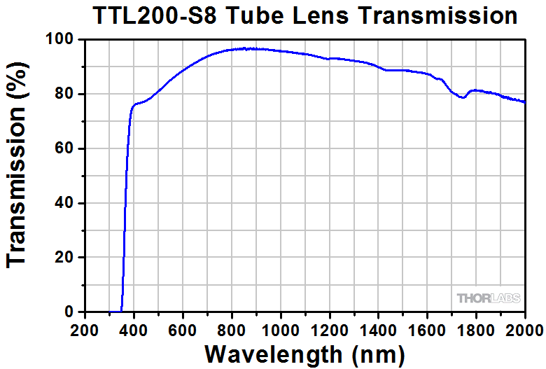
The TTL200-UVB tube lens features an air-spaced design for superior performance and high power handling. It is AR coated for UV wavelengths (240 - 360 nm) and is designed to be used with our high-power MicroSpot® focusing objectives. The tube lenses coated for visible wavelengths (350 - 700 nm) offer good performance at shorter wavelengths (<480 nm) to accommodate applications using 405 nm and 443 nm illumination. The TTL200-B is AR coated for NIR wavelengths (650 - 1050 nm), making it ideal for NIR fluorescence and NIR DIC imaging. The TTL200-S8 utilizes a broadband MgF2 single-layer coating with a low transmission roll-off throughout the visible and NIR, with peak transmission centered at 830 nm. See the graphs in Table G1.2 for transmission data. Some TTL series lenses can be custom coated with an AR coating optimized for transmission within the design wavelength range; contact Tech Sales for details.
Click to Enlarge
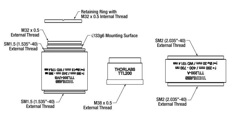
Figure G1.1 The three thread configurations available on our Widefield Imaging Tube Lenses are shown here with the objective-facing side down. Thead information for each Item # is provided in Table G1.2.
With the exception of the TTL200 and the ITL200, all of these tube lenses are engraved with an arrow next to an infinity symbol (∞) to indicate which side of the lens should face the objective (infinity space). Item #'s TTL200 and ITL200 should be inserted with the M38 x 0.5 threading facing the objective.
Mounting Options
The TTL200-UVB tube lens has a Ø33g6 surface for mounting on a compatible Mitutoyo microscope and can be secured in place using the included M32 x 0.5 threaded retaining ring (see the left-most tube lens in Figure G1.1). SM1.5 (1.535"-40) threading at each end of the tube lens can also be used for mounting or converted to external SM2 (2.035"-40) threading using the SM2A57 thread adapter.
The TTL200 and ITL200 lenses have external M38 x 0.5 threading for direct compatibility with Nikon and Thorlabs microscopes. This threading can be converted to external SM2 (2.035"-40) threading using the SM2A20 adapter available below. Alternatively, the WFA4111 dovetail adapter, also available below, directly accepts a TTL200 or ITL200 tube lens, allowing it to be integrated with a Cerna microscope.
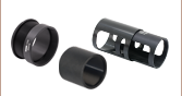
The rest of these lenses feature external SM2 (2.035"-40) threading on both sides that connects to our Ø2" lens tubes and many elements of our 60 mm cage system. Specifically, the TTL200-A, TTL200-S8, and TTL200-B tube lenses are compatible with our SM2L39 SM2-Threaded Lens Tube Spacer sold below, which is manufactured to be the exact length needed to position the sensor of a microscopy camera with a standard C-mount connection at the image plane of the tube lens when combined with an SM1A9 adapter, SM1ZM zoom housing, SM1L03 lens tube, and SM1A2 adapter; please see the Application tab for more details. The TTL180-A, TTL165-A, or TTL100-A tube lenses can be built into similar assemblies using the SM2L32, SM2L27, or SM2L04 lens tube spacers, respectively. Additionally, these tube lenses can be integrated with Thorlabs' Cerna® DIY Microscopy Systems by directly connecting to the SM2A59 Dovetail Adapter sold below.
| Table G1.2 Specifications | ||||||||
|---|---|---|---|---|---|---|---|---|
| Item # | Effective Focal Length |
Industry Objective Matcha |
Working Distanceb,c |
Design Wavelength Rangec |
AR Coating | External Threading |
Housing Length |
Transmission (Click for Graph) |
| TTL200-UVB | 200 mm ± 1% | Thorlabs, Mitutoyo | 176.4 mm | 248 to 700 nm | 240 to 360 nm | M32 x 0.5 (Top); SM1.5 (Top and Bottom) |
49.5 mm | |
| ITL200 | 200 mm | Thorlabs, Nikon, Leica, Mitutoyo |
148 mm | Visible Wavelengthsd | Visible Wavelengths | M38 x 0.5 (Bottom Only) |
28.0 mm | |
| TTL200 | 200 mm ± 1% | Thorlabs, Nikon, Leica, Mitutoyo |
148.6 mm | 400 to 750 nmd | 350 to 700 mm | M38 x 0.5 (Bottom Only) |
28.0 mm | |
| TTL200-A | 200 mm ± 1% | Thorlabs, Nikon, Leica, Mitutoyo |
151.8 mm | 400 to 750 nmd | 350 to 700 mm | SM2 (Top and Bottom) |
28.0 mm | |
| TTL200-S8 | 200 mm ± 1% | Thorlabs, Nikon, Leica, Mitutoyo |
151.8 mm | 400 to 2000 nmd | Broadband Single-Layer MgF2 |
SM2 (Top and Bottom) |
28.0 mm | |
| TTL200-B | 200 mm ± 1% | Thorlabs, Nikon, Leica, Mitutoyo |
151.8 mm | 650 to 1050 nm | 650 to 1050 nm | SM2 (Top and Bottom) |
28.0 mm | |
| TTL180-A | 180 mm ± 1% | Olympus | 133.5 mm | 400 to 750 nmd | 350 to 700 mm | SM2 (Top and Bottom) |
31.1 mm | |
| TTL165-A | 165 mm ± 1% | Zeiss | 120.6 mm | 400 to 750 nmd | 350 to 700 mm | SM2 (Top and Bottom) |
30.9 mm | |
| TTL100-A | 100 mm ± 1% | - | 63.1 mm | 450 to 750 nmd | 350 to 700 mm | SM2 (Top and Bottom) |
33.5 mm | |

 Zoom
Zoom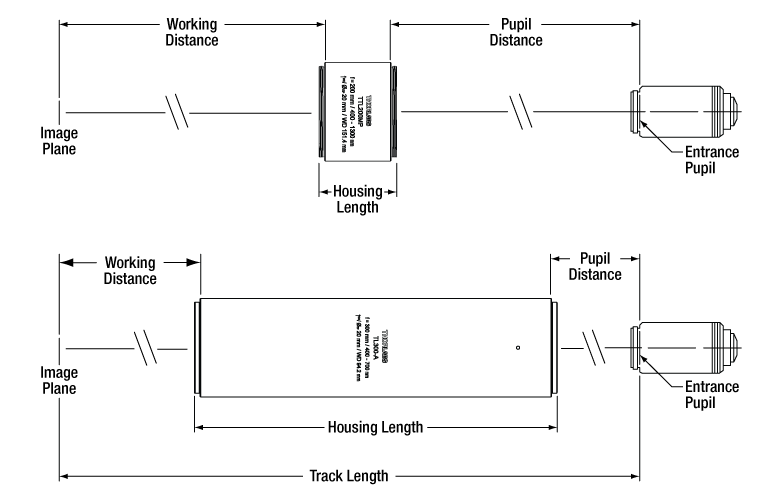
Click to Enlarge
Figure G2.1 The TL600-A, TL400-A, TL300-A, TTL200MP, and TTL200MP2 tube lenses are designed to have the same track length, defined as the distance between the image plane of the tube lens and the shoulder of the objective.
- 200 mm Effective Focal Length Used by Thorlabs, Nikon, Leica, and Mitutoyo
- 300 mm, 400 mm, and 600 mm Effective Focal Lengths for Increased Magnification in Standard Systems
- Telecentric Design
These infinity-corrected tube lenses feature a telecentric design appropriate for both laser scanning and widefield imaging applications. Our laser scanning tube lenses with a wavelength range from 400 to 700 nm or 450 to 1100 nm can be paired with our SL50-CLS2 (450 - 1100 nm) scan lens to create a telecentric system. Similarly, the TL200-2P2 and TL200-3P tube lenses are designed to be used with our SL50-2P2 (680 - 1300 nm) and SL50-3P (900 - 1900 nm) scan lenses, respectively. Due to the extended wavelength range of their AR coatings, the TTL200MP and TTL200MP2 can be paired with any of these three scan lenses. The TTL200MP tube lens provides higher transmission at visible and NIR wavelengths, while the TTL200MP2 tube lens provides higher transmission at longer wavelengths approaching 2000 nm; see full transmission data by clicking the graph icon in Table G2.2.
These tube lenses are engraved with an arrow next to an infinity symbol (∞) to indicate which side of the lens should face the objective (infinity space). The TL600-A, TL400-A, TL300-A, TTL200MP, and TTL200MP2 tube lenses are designed with the same nominal track length of 420 mm, allowing tube lenses of different focal lengths to be interchanged without realigning the imaging device or objective.
Some of these lenses can be custom coated with an AR coating optimized for transmission within the design wavelength range; contact Tech Sales for details.
Mounting Options
These tube lenses feature external SM2 (2.035"-40) threading on one or both sides that connects to our Ø2" lens tubes and many elements of our 60 mm Cage System. Specifically, the TTL200MP and TTL200MP2 tube lenses are compatible with our SM2L39 SM2-Threaded Lens Tube Spacer sold below, which is manufactured to be the exact length needed to position a microscopy camera with a standard C-mount connection at the image plane of the tube lens when combined with an SM1A9 adapter, SM1ZM zoom housing, SM1L03 lens tube, and SM1A2 adapter; please see the Application tab for more details. Additionally, these tube lenses can be integrated with Thorlabs' Cerna® DIY Microscopy Systems by directly connecting to the SM2A59 Dovetail Adapter sold below.
| Table G2.2 Specifications | ||||||||
|---|---|---|---|---|---|---|---|---|
| Item # | Effective Focal Length |
Industry Objective Matcha |
Working Distanceb,c |
Design Wavelength Ranged |
AR Coating | Threading | Housing Length |
Transmission (Click for Graph) |
| TL600-A | 600 mm ± 1% | - | 94.2 mm | 400 to 700 nm | 400 to 700 nm | External SM2 (Top and Bottom) |
205.7 mm | |
| TL400-A | 400 mm ± 1% | - | ||||||
| TL300-A | 300 mm ± 1% | - | ||||||
| TTL200MP | 200 mm ± 1% | Thorlabs, Nikon, Leica, Mitutoyo |
151.4 mm | 400 to 2000 nm | 400 to 1300 nm | 44.1 mm | |
|
| TTL200MP2 | Broadband Single-Layer MgF2 Coating |
|||||||
| TL200-CLS2 | 180.9 mm | 450 to 1100 nm | 450 to 1100 nm | External SM2 (Bottom), Internal SM2 (Top) |
41.6 mm | |
||
| TL200-2P2 | 680 to 1300 nm | 680 to 1300 nm | |
|||||
| TL200-3P | 900 to 1900 nm | 900 to 1900 nm | |
|||||
 Lens Tube Spacer for Infinity-Corrected Tube Lenses")
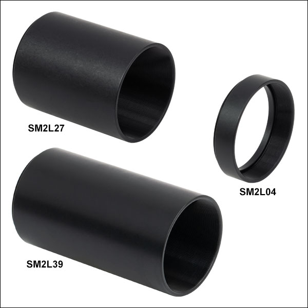 Zoom
Zoom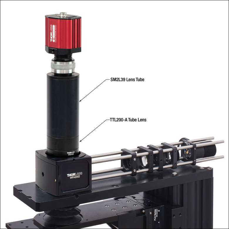
Click to Enlarge
Figure G3.1 An SM2L39 Lens Tube is used to position a microscopy camera with a standard
- Designed for Use in an Adjustable C-Mount to SM2 Camera Tube Assembly (See Application Tab)
- Compatible with Thorlabs' SM2-Threaded Infinity-Corrected Tube Lenses (See Table G3.2)
- Positions C-Mount Microscopy Cameras at the Image Plane of SM2-Threaded Tube Lenses
- Directly Compatible with SM2-Threaded (2.035"-40) Components
These Ø2" Lens Tubes are manufactured to be the exact length needed to position a microscopy camera with a standard
Each tube has an SM2-Threaded (2.035"-40) bore that accepts Ø2" (Ø50.8 mm) optics, and one SM2RR Retaining Ring is included with each lens tube. For SM2-threaded lens tubes with additional lengths, please see our Ø2" Stackable Lens Tubes.
*The lens tubes are designed to position the camera sensor at the image plane of the tube lens when the SM1ZM Zoom Housing is at the center of its adjustment range, allowing for ±1.75 mm travel.
| Table G3.2 Specifications | ||||
|---|---|---|---|---|
| Item # | L | Internal Thread Depth | Tube Lens Working Distancea | Recommended Tube Lensa |
| SM2L04 | 0.47" (11.9 mm) | 0.44" (11.0 mm) | 63.10 ± 1.75 mm | TTL100-A |
| SM2L27 | 2.73" (69.4 mm) | 2.70" (68.6 mm) | 120.60 ± 1.75 mm | TTL165-A |
| SM2L32 | 3.24" (82.2 mm) | 3.21" (81.4 mm) | 133.50 ± 1.75 mm | TTL180-A |
| SM2L39 | 3.96" (100.6 mm) | 3.93" (99.8 mm) | 151.88 ± 1.75 mm | TTL200-A, TTL200-B, TTL200-S8, TTL200MP, or TTL200MP2 |

 Zoom
Zoom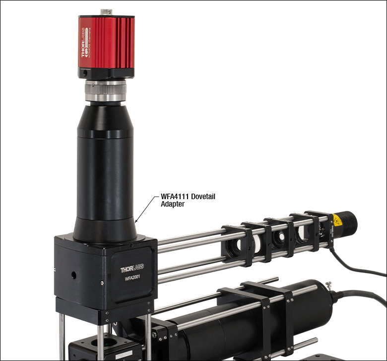
Click to Enlarge
Figure G4.1 A WFA4111 adapter can be used to integrate an external
- Easily Integrate Tube Lenses with Thorlabs' Construction Systems
- Options Available with Male D1N Dovetail for Using Tube Lenses in Cerna® DIY Systems and Microscopes
- Options Available for Compatibility with M38 x 0.5- and SM2-Threaded Tube Lenses
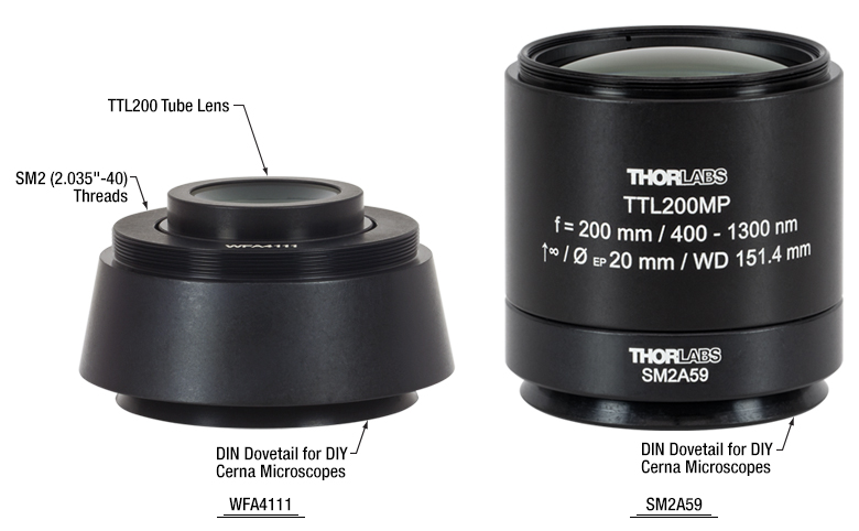
Click to Enlarge
Figure G4.2 The WFA4111 and SM2A59 adapters allow our infinity-corrected tube lenses to be easily integrated with Cerna microscopes and SM2-threaded components.
Thorlabs offers three styles of adapters for use with tube lenses that have M38 x 0.5 or SM2 (2.035"-40) threads, allowing them to be integrated with Thorlabs' SM2 lens tube systems and Cerna DIY Microscopy Platform.
The WFA4111 Dovetail Adapter features internal M38 x 0.5 threading for use with our TTL200 and ITL200 tube lenses. Alternatively, external SM2 threads on the top of the adapter allow externally SM2-threaded lenses to be connected via an SM2M05 lens tube. The SM2 threads on top can also be used to integrate user-designed camera tubes constructed from SM2-threaded lens tubes. The SM2A59 Dovetail Adapter features internal SM2 (2.035"-40) threading and directly accepts our SM2-threaded tube lenses. The internal SM2 threading can also be used to integrate with our SM2 lens tube systems for the construction of custom image detection modules. Both the WFA4111 and SM2A59 adapters feature a male D1N dovetail, making them compatible with our DIY Cerna systems.
The SM2A20 adapter also has internal M38 x 0.5 threads and allows the TTL200 and ITL200 tube lenses to be easily converted to SM2 threading. This allows for the construction of an optical system consisting of a scan lens and a tube lens using Thorlabs' standard SM2 lens tube components and the SM2-threaded GCM102(/M) 2D galvo mounting adapter. We also offer SM2-threaded adapters for common objective threads.
The SM38RR retaining ring can be used to lock the tube lens in place when using either the WFA4111 or the SM2A20 adapter.