 Products Home / Technical Resources / Camera and Camera Lens Technical Publications / Telecentric Lenses Tutorial
Telecentric Lenses Tutorial

Please Wait
Telecentric Lenses
Telecentric lenses are designed to have a constant magnification regardless of the object's distance or location in the field of view. This attribute is ideal for many machine vision measurement applications, as measurements of an object's dimensions will be independent of where it is located.
Types of Telecentric Lenses
In order to achieve a telecentric lens design, all of the chief rays (rays from an off-axis point that pass through the center of the aperture stop) have to be parallel to the optical axis in either image space or object space, or both.
For an object space telecentric lens, the chief rays will be parallel to the optical axis on the object's side of the lens (object space). This is accomplished by setting the aperture stop at the front focal plane of the lens, which results in an entrance pupil at infinity. Since chief rays are directed towards the center of the entrance pupil, the chief rays on the object side of the lens will be parallel to the optical axis. An example of an object space telecentric lens is shown in Figure 119A.
For an image space telecentric lens, the chief rays will be parallel to the optical axis on the image's side of the lens (image space). This is accomplished by setting the aperture stop at the back focal plane of the lens, which results in an exit pupil at infinity. Since the chief rays must pass through the center of the exit pupil, the chief rays on the image side of the lens must be parallel to the optical axis. An example of an image space telecentric lens is shown in Figure 119B.
Click to Enlarge
Figure 119A A ray trace through an idealized object space telecentric lens system. Note that the chief rays (the center ray of each color) are parallel to the optical axis in object space, but in image space, the chief rays form an angle with the optical axis.
Click to Enlarge
Figure 119B A ray trace through an idealized image space telecentric lens system. Note that the chief rays (the center ray of each color) are parallel to the optical axis in image space, but in object space, the chief rays form an angle with the optical axis.
For a double telecentric, or bi-telecentric, lens, the front and back focal planes are made to overlap so that the aperture stop is located where both the entrance and exit pupils are at infinity. In a bi-telecentric lens, neither the image or object location will affect the magnification. Thorlabs' telecentric lenses are all bi-telecentric designs. Figure 119C shows an example ray trace through a bi-telecentric lens and illustrates how the chief rays pass through the system.
Click to Enlarge
Figure 119C A ray trace through an idealized bi-telecentric lens system. Note that the chief rays (the center ray of each color) are parallel to the optical axis in both image and object space, which means that the magnification will remain constant regardless of object distance.
Conventional Lenses
In conventional lenses, the entrance and exit pupils are not located at infinity, so the chief rays will not be parallel to the optical axis. In this case, the magnification of the object depends on its distance from the lens and its position in the field of view. Figure 119D shows an example ray trace through a conventional camera lens; notice how the chief rays are angled with respect to the optical axis in both image and object space. Note that both Figures 119C and 119D feature the same lens design; only the aperture stop location was varied to shift the bi-telecentric system to a non-telecentric one.
Click to Enlarge
Figure 119D A ray trace through an idealized conventional camera lens system. Note that the chief rays (the center ray of each color) are not parallel to the optical axis in both image and object space, which means that the magnification will vary with object distance.
Example Images
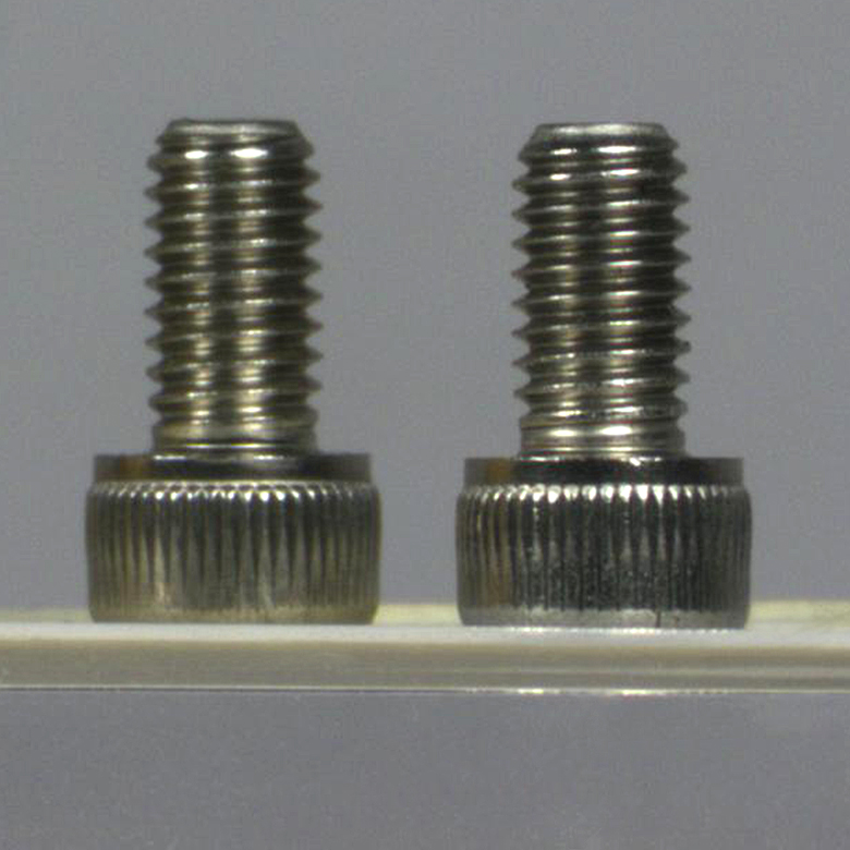
Figures 119E and 119F show photographs taken with a bi-telecentric lens and a standard camera lens, respectively. With the telecentric imaging system, the height of the two screws appears to be the same, even though the object planes are separated by approximately 45 mm along the optical axis. With the conventional imaging system, the two screws appear to be different heights, which could result in inaccurate dimensional measurements. A machine vision system using a bi-telecentric lens can offer advantages for dimensional metrology. For example, these lenses can be integrated into our Multi-Sensor Video Measurement Machines.
Click to Enlarge
Figure 119E An image of two identical 8-32 cap screws imaged with our previous generation MVTC23013 0.128X Telecentric Lens. Although the screws appear to be the same size and in the same object plane, they are actually separated by a distance of approximately 45 mm along the optical axis.

Click to Enlarge
Figure 119F The same two screws photographed with our previous-generation MVL7000 conventional zoom lens. The MVL7002 lens provides similar performance. In this image, the perspective error due to the separation of the screws would lead to incorrect height measurements.
| Posted Comments: | |
John Chapman
(posted 2024-08-12 23:07:04.777) the bi-telecentric ray diagram seems the same as the object-space diagram. cdolbashian
(posted 2024-12-26 01:51:47.0) Thank you for reaching out to us with this observation! You will note, however, following the caption for each of these, that the difference is in the angle of the chief ray in image space. The Bi-telecentric lens has chief rays which are parallel to each other in both spaces, while the object-space telecentric lens does not. Christoph Alt
(posted 2024-07-05 08:52:16.54) Hello,
I think there is a confusion between front and back focal planes in the below sentences, compare e.g. Wikipedia: https://en.wikipedia.org/wiki/Telecentric_lens
1.
"This is accomplished by setting the aperture stop at the front focal plane of the lens, which results in an entrance pupil at infinity."
In my opinion, it should be:
"This is accomplished by setting the aperture stop at the back focal plane of the lens, which results in an entrance pupil at infinity."
2.
"This is accomplished by setting the aperture stop at the back focal plane of the lens, which results in an exit pupil at infinity."
This should be:
"This is accomplished by setting the aperture stop at the front focal plane of the lens, which results in an exit pupil at infinity." cdolbashian
(posted 2024-08-01 03:12:29.0) Thank you for reaching out to us with this feedback. It seems like you are indeed correct here. As of the time of posting this, we are updating the tutorial to reflect the correct information. HB Shin
(posted 2023-05-14 00:01:41.91) I tried to make bi-telecentric lens set, and purchased LB1761 (F=25.4mm, back focal length=22.2mm) and LB1471 (F=50.0mm, back focal length=48.2mm). I placed two lens with 70.4 mm spacing, that is, vertex to vertex distance. And then, I put the lens system onto CMOS camera, but it catchs the image only at some distance. Do I calculate the focal distance in a wrong way? ksosnowski
(posted 2023-05-25 10:54:04.0) Thanks for reaching out to Thorlabs. Typically some aperture stop is used in bitelecentric systems, and while magnification doesn't change with distance in these systems, there is still a finite depth of field. I have reached out to discuss this application in more detail. mojtaba seydi
(posted 2019-06-03 11:58:19.72) Hello. There is a typo in the "Conventional Lenses" part, when you want to refer figure 3. "figure 2 is wrong" YLohia
(posted 2019-06-03 11:36:26.0) Hello, thank you for bringing this typo to our attention! We're working to get this corrected. |