 Products Home / Active Optical Devices / Optical Amplifiers / C-Band Optical Amplifiers (BOAs and SOAs), 1550 nm
C-Band Optical Amplifiers (BOAs and SOAs), 1550 nm
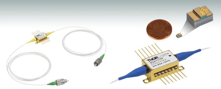
- Compact Optical Amplifier in Butterfly Package
- Low Noise, Broad, Flat Optical Bandwidth, High Saturation Power (>15 dBm)
- Polarization-Independent and Polarization-Maintaining Versions
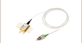
BOA1004S
BOA with SM Fiber and FC/APC Connectors
BOA1007C
Actual Size Compared to a U.S. Penny
SOA1117P
SOA with PM Fiber and FC/APC Connectors, Close-up of Butterfly Package Shown


Please Wait
| Optical Amplifier Selection Guide |
|---|
| 780 - 795 nm BOAs |
| 830 nm BOAs |
| 930 nm BOAs |
| 980 nm BOAs |
| 1050 nm BOAs |
| 1210 nm BOAs |
| 1250 nm BOAs |
| O-Band (1280 - 1350 nm) BOAs |
| E-Band (1410 nm) BOAs |
| C-Band (1520 - 1550 nm) BOAs and SOAs |
| L-Band (1590 - 1625 nm) BOAs |
| 1685 nm BOAs |
| 1700 nm BOAs |
Click to Enlarge
Figure 1.1 When current is applied across the ridge waveguide, excited state electrons are stimulated by input light, leading to photon replication and signal gain.
Features
- Booster Optical Amplifier (BOA)
- Polarization Maintaining: Amplifies Only One Polarization State
- Single Mode (SM) or Polarization-Maintaining (PM) Fiber Pigtails (1.5 m) with FC/APC Connectors
- Free-Space Chips Offered on Submount or Heatsink
- Typical Applications: Boosting Laser Transmitters, Compensating for Transmit MUX/DeMUX Insertion Loss, Optical Shutter
- Semiconductor Optical Amplifier (SOA)
- Polarization Independent: Amplifies All Polarization States
- SM or PM Fiber Pigtails (1.5 m) with FC/APC Connectors
- Typical Applications: Inline Amplifier, Detector Pre-Amp, Fast Optical Switch
(~1 ns Switching Speed)
BOAs and SOAs are single-pass, traveling-wave amplifiers that perform well with both monochromatic and multi-wavelength signals. Since BOAs only amplify one state of polarization, they are best suited for applications where the input polarization of the light is known. For applications where the input polarization is unknown or fluctuates, SOAs are required. However, the gain, noise, bandwidth, and saturation power specifications of a BOA are superior to that of a SOA because of the design features that make the SOA polarization insensitive.
Click to Enlarge
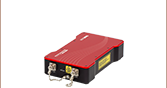
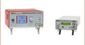
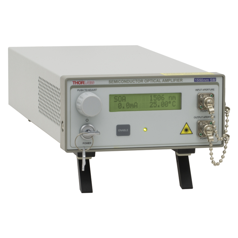
Figure 1.2 Our SOA1117S and BOA1004P optical amplifiers are also available in the S7FC1013S and S9FC1004P benchtop optical amplifiers, respectively.
Thorlabs offers fiber-coupled BOAs and SOAs that exhibit low coupling losses, as well as free-space BOAs as a chip on submount (C) or chip on heatsink (H). Losses typically range from 1.5 to 2.5 dB for the fiber-to-chip and chip-to-fiber coupling (each). This affects the total gain, noise figure (NF), and saturation power (Psat). While the gain produced by the amplifier exceeds that of the losses, these losses remain an important factor in determining the device's performance. For instance, a 1 dB drop in input coupling efficiency increases the noise figure by 1 dB. Alternatively, a 1 dB drop in output coupling decreases the saturation power by 1 dB.
Mount and Driver Options
These butterfly packages are compatible with the CLD1015 laser diode mount with integrated controller and TEC. When operating the BOAs on this page with the CLD1015, the orientation for type 1 pin configurations should be used. They are also compatible with the LM14TS and LM14S2 mounts, which can be used with our laser diode, TEC, and combined current/TEC controllers. When operating these lasers in environments with more than 5 °C variation in temperature, we recommend using the LM14TS mount, which provides active control of the butterfly package's case temperature to stabilize the amplifier's output wavelength and power.
Center Wavelength Note
The center wavelength (CWL) of the ASE spectrum in broadband semiconductor devices such as optical amplifiers may show variation between lots. Please refer to the Specs tab for the CWL tolerances of each particular model. For applications in which a specific ASE center wavelength is a critical concern, please contact Tech Sales for information on the CWL of currently available lots.
Booter Optical Amplifiers in Butterfly Packages
| Item # | BOA1004S and BOA1004P | BOA1550S and BOA1550P | BOA1554 and BOA1554P | |||||||
|---|---|---|---|---|---|---|---|---|---|---|
| Parametera | Symbol | Min | Typical | Max | Min | Typical | Max | Min | Typical | Max |
| Operating Current | IOP | - | 600 mA | 750 mA | - | 900 mA | 950 mA | - | 1700 mA | 1800 mA |
| Center Wavelength | λC | 1530 nm | 1550 nm | 1570 nm | 1530 nmb | 1550 nmb | 1580 nmb | 1510 nm | 1520 nm | 1560 nm |
| ASE Optical 3 dB Bandwidth | BW | 80 nm | 85 nm | - | 95 nm | 105 nm | - | 62 nm | 72 nm | - |
| Saturation Output Powerc (@ -3 dB) | PSAT | 13 dBm | 15 dBm | - | 17 dBmd,e | 18 dBmd,e | - | - | - | - |
| Achieved Output Power (@ PIN = 10 mW)d,e,f | P | - | - | - | - | - | - | 21.14 dBm (130 mW) |
22.04 dBm (160 mW) |
- |
| Small Signal Gain (@ PIN = -20 dBm) | G | 23 dBd | 27 dBd | - | 24 dBd,e | 27 dBd,e | - | 32 dB | 35 dB | - |
| Gain Ripple (RMS)e | δG | - | 0.05 dB | 0.3 dB | - | 0.04 dB | 0.3 dB | - | 0.15 dB | 0.50 dB |
| Polarization Extinction Ratio | PER | - | 18 dB | - | - | 18 dBg | - | 15 dBh | 23 dBh | - |
| Noise Figure | NF | - | 7.5 dB | 9 dB | - | 8.5 dBd,e | 9.5 dBd,e | - | 7.5 dBd,e | 10.0 dBd,e |
| Forward Voltage | VF | - | 1.3 V | 1.6 V | - | 1.6 V | 2.1 V | - | 1.5 V | 2.2 V |
| Chip Length | - | - | 1.5 mm | - | - | 1.5 mm | - | - | - | - |
| Waveguide Refractive Index | - | - | 3.2 | - | - | - | - | - | - | - |
| TEC Operation (Typical/Max @ TCASE = 25 °C/70 °C)i | ||||||||||
| TEC Current | ITEC | - | 0.13 A | 1.5 A | - | 0.55 A | 1.5 A | - | 1.0 A | 2.5 A |
| TEC Voltage | VTEC | - | 0.28 V | 4.0 V | - | 0.70 V | 4.0 V | - | 1.3 V | 4.0 V |
| Thermistor Resistance | RTH | - | 10 kΩ | - | - | 10 kΩ | - | - | 10 kΩ | - |
Semiconductor Optical Amplifiers in Butterfly Packages
| Item # | SOA1013S | SOA1117S and SOA1117P | |||||
|---|---|---|---|---|---|---|---|
| Parameter | Symbol | Min | Typical | Max | Min | Typical | Max |
| Operating Current | IOP | - | 500 mA | 750 mA | - | 500 mA | 600 mA |
| Operating Wavelength Range | - | 1528 nm | - | 1562 nm | 1528 nm | - | 1562 nm |
| Center Wavelength | λC | - | 1500 nma | - | - | 1550 nm | - |
| Saturation Output Powerb (@ -3 dB) | PSAT | 12 dBm | 14 dBm | - | 6 dBmc | 9 dBmc | - |
| Small Signal Gain (Over C-Band @ Pin = -20 dBm) | G | 10 dB | 13 dB | - | 15 dB | 20 dB | - |
| Gain Flatness (Over C-Band @ Pin = -20 dBm) | ΔG | - | 5 dB | 7 dB | - | - | - |
| Gain Ripple (p-p) @ IOP, λC | δG | - | 0.1 dB | 0.5 dB | - | 0.2 dB | 0.5 dB |
| Polarization Dependent Gain | PDG | - | 1.0 dB | 1.8 dB | - | 1 dB | 2.5 dB |
| Noise Figure | NF | - | 8 dB | 9.5 dB | - | 10 dB | 11.5 dB |
| Forward Voltage | VF | - | 1.6 V | 1.8 V | - | 1.4 V | 2.0 V |
| Chip Length | - | - | 1.5 mm | - | - | 1.0 mm | - |
| Waveguide Refractive Index | - | - | 3.2 | - | - | 3.2 | - |
| TEC Operation (Typical/Max @ TCASE = 25/70 °C) | |||||||
| TEC Current | ITEC | - | 0.23 A | 1.5 A | - | 0.2 A | 1.5 A |
| TEC Voltage | VTEC | - | 0.5 V | 4.0 V | - | 0.4 V | 4.0 V |
| Thermistor Resistance | RTH | - | 10 kΩ | - | - | 10 kΩ | - |
Booster Optical Amplifier Chips
| Item # | BOA1007C and BOA1007H | |||
|---|---|---|---|---|
| Parameter | Symbol | Min | Typical | Max |
| Operating Current | IOP | - | 600 mA | 750 mA |
| Central Wavelength | λC | 1530 nm | 1550 nm | 1580 nm |
| Optical 3 dB Bandwidth | BW | 80 nm | 85 nm | - |
| Saturation Output Powera (@ -3 dB) | PSAT | 15 dBm | 18 dBm | - |
| Small Signal Gain (@ PIN = -20 dBm, λ = 1550 nm) | G | 26 dB | 30 dB | - |
| Gain Ripple (RMS) @ IOP | δG | - | 0.05 dB | 0.3 dB |
| Polarization Extinction Ratio | PER | - | 18 dB | - |
| Chip Noise Figure | NF | - | 6.0 dB | 8.0 dB |
| Forward Voltage | VF | - | 1.3 V | 1.6 V |
| Chip Length | L | - | 1.5 mm | - |
| Waveguide Refractive Index | - | 3.2 | - | |
| Lateral Beam Exit Angle | ΘEXT | - | 19.5° | - |
| Beam Divergence Angle (FWHM) | ||||
| Transverse | ΘT | 26° | 34° | 42° |
| Lateral | ΘL | 10° | 14° | 30° |
Click to Enlarge
Figure 1: Diagram of the BOA1007C (top down view). The anode and cathode sections of the chip are highlighted here. Please note that the BOA1007H has the same chip structure, and thus, its anode and cathode sections can be similarly determined.
Note: All plots illustrate typical performance, and individual units may have slightly different performance, within the parameters outlined on the Specs tab.
BOA1004S and BOA1004P Graphs

BOA1550S Graphs


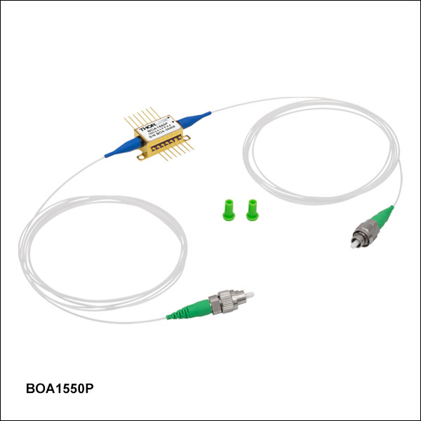
BOA1550P Graphs


BOA1554 Graphs


BOA1554P Graphs

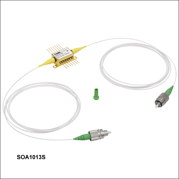
SOA1013S Graphs
SOA1117S and SOA1117P Graphs

BOA1007C and BOA1007H Graphs
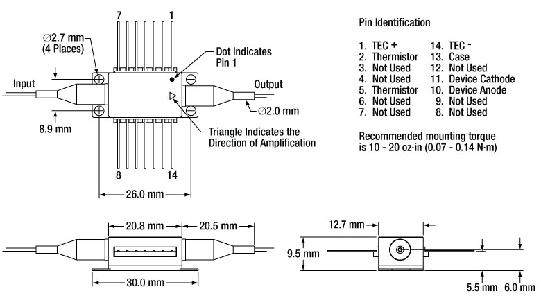
Mechanical Drawing and Pin Assignments for Butterfly Package
Booster optical amplifiers (BOAs) and semiconductor optical amplifiers (SOAs) are single-pass, traveling-wave amplifiers that perform well with both monochromatic and multi-wavelength signals. Since BOAs only amplify one state of polarization, they are best suited for applications where the input polarization of the light is known. For applications where the input polarization is unknown or fluctuates, SOAs are required. However, the gain, noise, bandwidth, and saturation power specifications of a BOA are superior to that of a SOA because of the design features that make the SOA polarization insensitive.
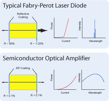
BOAs and SOAs are similar in design to Fabry-Perot Laser Diodes, the difference being that Fabry-Perot laser diodes have reflective coatings on both end faces of the semiconductor chip. The optical feedback from the reflective end faces establishes a cavity in which lasing can occur. SOAs and BOAs have an anti-reflection (AR) coating on both end faces of the semiconductor chip. The AR coatings limit the optical feedback into the chip so that lasing does not occur.
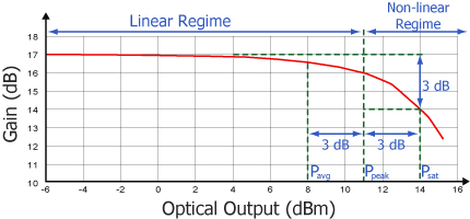
As is typical for all amplifiers, BOAs/SOAs operate in two regimes: a linear, flat, constant gain regime and a non-linear, saturated output regime. When used to amplify a modulated signal, the linear regime is typically used to eliminate pattern-dependent distortion, multi-channel cross-talk, and transient response issues common to EDFAs. The non-linear regime is used to take advantage of the highly non-linear attributes of the semiconductor gain medium (cross-gain modulation, cross phase modulation) to perform wavelength conversion, optical 3R regeneration, header recognition, and other high-speed optical signal processing functions.
For a continuous wave input signal, the amount of power that can be produced by the amplifier is determined by the saturation output power (Psat) parameter. Psat is defined as the output power at which the small-signal gain has been compressed by 3 dB. The maximum amount of CW power that can be extracted is approximately 3 dB higher than the saturation power.
| Posted Comments: | |
Ziya Keskin
(posted 2025-06-30 14:37:01.113) Hello, regarding the BOA1550P, what is the maximum output power at 1510nm? EGies
(posted 2025-07-01 06:38:14.0) Thank you for contacting Thorlabs. We have not explicitly tested the maximum output power from the BOA1550P at 1510nm, but we may be able to extrapolate how we'd expect the BOA to behave. I have reached out to you directly regarding this. William Swann
(posted 2024-10-18 13:51:24.067) Hello Thorlabs, We would like to know if your SOA1117S can operate bi-directionally, that is will it simultaneously amplify a signal entering the output and exiting the input along with a signal entering the input and exiting the output? If it cannot operate this way, can you comment as to why not? Thank you. jpolaris
(posted 2024-10-22 08:15:47.0) Thank you for contacting Thorlabs. These SOAs are built with a symmetric structure so they can be used bidirectionally and the gain will be the same. However, if it is operated backwards, it is likely that the saturation power and the noise figure will deviate from their specified values because it is common for the coupling efficiencies of the input and output fibers to be different. user
(posted 2022-08-16 11:49:50.877) i'm using BOA1004P on our project and i want to operate BOA1004P on 35°C. So i want to know BOA1004P's thermistor temperature coefficient or equation.
Thank you. ksosnowski
(posted 2022-08-23 01:17:38.0) Thanks for reaching out to Thorlabs. We use the same 10kOhm thermistor in most of our butterfly devices. The Steinhart-Hart coefficients for this are as follows: A= 1.129241E-03, B= 2.341077E-04, C= 8.775468E-08. user
(posted 2021-02-17 08:04:44.963) Dear Sir or Madam,
I could not find following information in the spec sheet:
(1) FC/APC connector key is aligned to slow or fast axis?
(2) Amplification is really aligned to fast axis as commented in Feedback section? (slow axis typically is better suited for PM stability and wide spread standard)
(3) What is the absorption value of the BOA when short circuit? Preferably high, in range 40...50dB?
Thank you very much YLohia
(posted 2021-03-12 04:47:46.0) Hello, thank you for contacting Thorlabs. (1) It is aligned to the slow-axis (2) It is aligned to the slow axis, not the fast axis (3) Unfortunately, we don’t have spec of absorption value for BOA1004P when no current is applied. If you have a key requirement for it, the BOA1004PXS would be more suitable since it has an isolation spec of > 40 dB when no current is applied. alexey Kokhanovskiy
(posted 2020-12-01 00:26:02.43) Dear Sir/Mme
We have purchased BOA1004P. What state of the polarization does BOA amplifies? That goes along fast or slow axis of PM fiber?
With respect,
Alexey Kokhanovskiy YLohia
(posted 2020-12-01 10:20:21.0) Hello Alexey, thank you for contacting Thorlabs. The BOA amplifies the polarization state along the slow axis of the fiber. Vasili Savitski
(posted 2020-04-07 05:11:46.033) Hi. Could you please give some numbers on the rise time of your BOA and SOA working in pulsed regime? Thank you. YLohia
(posted 2020-04-07 09:24:54.0) Hello, thank you for contacting Thorlabs. We have seen rise times on the order of hundreds of picoseconds for these BOAs in the past. Unfortunately, we do not have a formal rise time spec for these. I have reached out to you directly to discuss this further. DH Lee
(posted 2019-08-08 19:24:22.277) Can you show me the width and height of the ridge waveguide? YLohia
(posted 2019-08-09 09:56:59.0) Hello, thank you for contacting Thorlabs. Unfortunately, we cannot share this information as it is proprietary. We do, however, post the chip length, refractive index, and transverse/lateral beam divergence angles for the BOA1007C (see Specs tab for more information). yedukondalu patha
(posted 2019-05-16 08:09:06.867) Could you please send the manual, how to operate SOA1117S.
Thanks,
Yedukondalu P YLohia
(posted 2019-05-16 09:02:47.0) Hello Yedukondalu, thank you for contacting Thorlabs. Unfortunately, we do not offer a manual for this as the operation is very similar to that of a regular butterfly pigtail laser diode. I have reached out to you directly to discuss your application further and offer any assistance I can. kimyeonhwa1006
(posted 2018-10-15 21:07:20.387) Hi, I have a question for SOA graphs. I'm just wondering that the reason why the SOA 1013S and SOA1117S has different tendency according to Gain vs wavelength.
The graph of SOA 1013S in appendix tends to be decreased while that of SOA 1117S tends to be increased. I'm waiting for your reply. Thank you. YLohia
(posted 2018-10-19 12:08:41.0) Hello, thank you for contacting Thorlabs. The reason is that the peak of the ASE for SOA1013S happens at ~1500-1510 and that of the SOA1117S is at ~1550nm. Thus, based on the 1528-1562nm (C-band) region shown in the plots in question, the plot decreases for SOA1013S and increases for SOA1117S. Both of SOA1013S and SOA1117S are for C-band applications and we only test gain across this window. For the SOA1013S, which is marketed as a linear device (due to its high saturation power), we intentionally set peak gain wavelength at ~1500nm to obtain higher saturation power in the C-band. The saturation power tends to be higher on the longer wavelength side of the peak. kyeongpyo.lee
(posted 2018-09-19 05:10:10.58) I was testing the small signal gain by using BOA1007H, and I found that whatever the input power is (i.e. -50dBm or -20dBm) its amplified output is fixed at about -13dBm for 200mA current supply. I cannot understand this situation. Is it possible to do so? YLohia
(posted 2018-09-25 10:05:02.0) Hello, thank you for contacting Thorlabs. Please note that the performance of the BOA is highly dependent on its junction temperature and, thus, the unit should be used under properly temperature controlled environments. The BOA1007H will already start to produce gain (around 10-20dB) even with a 200mA drive current at 1550nm. It is quite likely that your input coupling efficiency to the BOA is not high enough, which would imply that the chip is not receiving enough light to amplify. The measured power then will be the BOA's ASE power itself, which can be around 5mW at 500-600mA of drive current. This is the fixed output you are seeing at these low input power levels. If you find that the power of your signal of interest is not high enough compared to the ASE, you may want to use spectral filters to attenuate the ASE signal. FBH1550-12 or FB1550-12 would be good choices to look into for the 1550nm center wavelength. mdrolet
(posted 2018-09-09 22:39:48.94) Hi, Do you have any graph showing amplification in pulsed regime?
Thanks,
Mathieu YLohia
(posted 2018-09-17 02:22:57.0) Hello Mathieu, thank you for contacting Thorlabs. Based on our discussion, your 150ns pulse width with 40 kHz rep rate supplied to this SOA will be perfectly fine, assuming that you use appropriate drivers/mounts. I have reached out to you directly with an eye diagram for an informal test we performed on one of our SOAs in the past/ jchg2758
(posted 2018-08-27 07:28:15.16) Can I know the general recovery time of those c-band SOAs? I want to know how fast pulse train could be applied to this amplifier.
Thanks. YLohia
(posted 2018-08-27 10:53:12.0) Thank you for contacting Thorlabs. SOA1117S gain recovery time is not a parameter that we specify or measure, but we expect it to be in the 300-500 ps range (potentially on the faster side). robert.supe
(posted 2017-10-02 10:13:51.683) in regards to product BOA1007C. We have several units and the height of each chip varies greatly. from 905um to 765um. I am unable to locate a height specification or tolerance on any of the data sheet provided on the website for the product. In order to proceed with our product development we need to know what the tolerances and specifications are for this product. Are there any which can be provided? tfrisch
(posted 2017-10-02 06:22:35.0) Hello, thank you for contacting Thorlabs. We will reach out to you directly to discuss these tolerances. hvdbrom
(posted 2015-12-15 17:24:51.02) Is this amplifier meant for CW or for digital signals? We need to amplify digital signals with pulse repetition rate of 10 Gb/s or 20 Gb/s. besembeson
(posted 2015-12-16 09:52:24.0) Response from Bweh at Thorlabs USA: Yes these can amplify a 10Gb/s or 20Gb/s modulated optical input as well as cw. In fact, the original application of the SOA design was a telecom alternative to EDFAs. However, the peak power levels will be limited to the cw saturation power. bdada
(posted 2011-09-09 11:09:00.0) Response from Buki at Thorlabs:
Thank you for using our Feedback tool. We apologize for not providing the drawing for the BOA1007H on our website. We will add it shortly. In the meantime, please refer to SAF1093H, which has the same mechanical drawing as the BOA1007H.
You can access the drawing on the right side of the SAF1093H product page linked below.
http://www.thorlabs.com/thorProduct.cfm?partNumber=SAF1093H jikim
(posted 2011-09-09 11:34:06.0) I would like to ask the mechanical dimensions of a BOA1007H. Before ordering such parameters are important for the design of our experiment. Thanks in advance. jjurado
(posted 2011-05-18 13:08:00.0) Response from Javier at Thorlabs to jikim: Thank you very much for contacting us. You are correct, since SOA is polarization dependent, the gain at fix current and wavelength will vary if the polarization state of the input changes. So, the maximum and minimum gain curves just describe the window of gain changes vs. polarization state. The difference between the max. and min, gain values correspond, then, to the polarization dependent gain (PDG) spec in the Specs tab. jikim
(posted 2011-05-18 15:00:18.0) In the performance plots of a SOA1013S, the maximum and minimum gain are shown. What does it mean? Are they the gains for different input polarizations, i.e. for TM and TE modes? Thorlabs
(posted 2010-08-26 14:54:46.0) Response from Javier at Thorlabs to jikim: The chip lengths for all our SOA/BOAs is 1.5 mm, except for the SOA1117, which has a length = 1.0 mm. I will contact you directly regarding the refractive index, since this information is not currently readily available. jikim
(posted 2010-08-26 10:58:25.0) Could you specify the length of the chip and its refractive index at 1550 nm? Adam
(posted 2010-04-23 12:15:21.0) A response from Adam at Thorlabs to jikim: I apologize for the confusion. The fiber to chip loss is 2.5dB and the chip to fiber loss is also 2.5dB. The total dB loss from fiber to fiber is 5dB. jikim
(posted 2010-04-23 09:00:15.0) Do you mean that fiber-to-chip loss is 2.5 dB and chip-to-fiber loss is also 2.5 dB? Or the loss of each side consisting of a surface of the chip and a fiber? Adam
(posted 2010-04-20 16:44:21.0) A response from Adam at Thorlabs to Jikim. The coupling losses at each side is 2.5dB. jikim
(posted 2010-04-20 10:38:13.0) Dear Thorlabs,
I have a simple question on a fibre-coupled BOA (BOA1004S). In this device, a pair of fibers is connected. Thus, there should be a certain amount of the coupling losses, e.g. fiber to the chip and chip to the fiber. Could you let me know such coupling losses? They are very important parameter in my laser system.
And Im looking forward to hearing from you soon.
Best Regards,
Jae-Ihn Kim
===============================================
Dr. Jae-Ihn Kim
- Scientific Assistant -
Technische Universitaet Kaiserslautern
Fachbereich Physik
Erwin-Schroedinger-Str.
(Postfach 3049)
67653 Kaiserslautern - Germany
Tel: (49) - 631 - 205 - 2319
Fax: (49) - 631 - 205 - 3903
http://www.physik.uni-kl.de/bergmann/
=============================================== Adam
(posted 2010-03-18 16:56:29.0) A response from Adam at Thorlabs to Sema: Previously, Covega has produced BOAs at this range, 1060nm. Thorlabs Quantum Electronics is planning on releasing a similar BOA in the next couple months. Will this work? At this time, there are no plans for the release of a SOA at this wavelength range, but if we can get more information about your application, I can suggest this as a new product idea. That being said, do you need a BOA or a SOA? Previously, most of our customer at this wavelength were either (1) making a laser for OCT or (2) amplifying 1064nm seed laser-- both of which a BOA is better suited than an SOA. I will email you to get more information for your application so we can suggest the most suitable product. sema
(posted 2010-03-18 10:20:02.0) Covega also used to produce SOAs for 1060 nm. Are these devices still available? |

 Zoom
Zoom- Polarization Maintaining: Amplifies Only One Polarization State
- SM or PM Fiber Pigtails (1.5 m) with FC/APC Connectors
- Typical Applications: Boosting Laser Transmitters, Compensating for Transmit MUX/DeMUX Insertion Loss, Optical Shutter
These BOAs consist of a highly efficient InP/InGaAsP Multiple Quantum Well (MQW) layer structure. As seen in Figure 1.1, the input and output of the amplifier is coupled to the reliable ridge waveguide on the optical amplifier chip. C-Band BOAs are available in a standard 14-pin butterfly package with either SM-fiber or PM-fiber pigtails that are terminated with FC/APC connectors. The connector key is aligned to the slow axis on all PM-fiber-pigtailed models. Optional polarization-maintaining isolators at the input, output, or both input/output are also available (specifications may vary with different configurations). Please contact Tech Sales to order such a device.
| Item #a | Center Wavelength | 3 dB Bandwidth | Saturated Output Power (@ -3 dB)b |
Achieved Output Power (@ PIN = 10 mW)c |
Small Signal Gain (@ PIN = -20 dBm) |
Noise Figure | Fiber Type |
Connector Types |
|---|---|---|---|---|---|---|---|---|
| BOA1554 | 1520 nmd | 62 nm | - | 22.04 dBm (160 mW)e,f | 35 dBe,f | 7.5 dBe,f | SM Fiber | FC/APC |
| BOA1554P | PM Fiber | |||||||
| BOA1004S | 1550 nm | 85 nm | 15 dBm | - | 27 dBe | 7.5 dB | SM Fiber | |
| BOA1004P | PM Fiber | |||||||
| BOA1550S | 1550 nmg | 105 nm | 18 dBme,f | - | 27 dBe,f | 8.5 dB | SM Fiber | |
| BOA1550P | PM Fiber |

 Zoom
Zoom- Polarization Independent: Amplifies All Polarization States
- SM or PM Fiber Pigtails (1.5 m) with FC/APC Connectors
- Typical Applications: Inline Amplifier, Detector Pre-Amp, Fast Optical Switch (~1 ns Switching Speed)
These Semiconductor Optical Amplifiers (SOAs) are polarization insensitive optical amplifiers; therefore, all polarization states are amplified. These devices are an ideal in-line amplifier. Advanced epitaxial wafer growth and opto-electronic packaging techniques enable a high output saturation power, low noise figure, and large gain across a broad spectral bandwidth. These devices come in an industry-standard 14-pin butterfly package with either SM-fiber or PM-fiber pigtails that are terminated with FC/APC connectors. The connector key is aligned to the slow axis on all PM-fiber-pigtailed models. These come without isolators, but we are able to provide units with polarization-insensitive isolators at the input, output, or both. Please contact Tech Sales for help in ordering such a device.
| Item #a | Center Wavelength | 3 dB Bandwidth | Saturated Output Power (@ -3 dB) |
Small Signal Gain (@ Pin = -20 dBm) |
Noise Figure | Fiber Type |
Connector Type |
|---|---|---|---|---|---|---|---|
| SOA1013S | 1500 nmb | - | 14 dBm | 13 dB | 8.0 dB | SM Fiber | FC/APC |
| SOA1117S | 9 dBm | 20 dB | 10.0 dB | ||||
| SOA1117P | PM Fiber |

 Zoom
ZoomThorlabs offers free-space BOAs, either as a chip on submount (C) or chip on heatsink (H).
| Item #a | Center Wavelength | 3 dB Bandwidth | Saturated Output Power (@ -3 dB) |
Small Signal Gain (@ Pin = -20 dBm) |
Noise Figure |
|---|---|---|---|---|---|
| BOA1007C | 1550 nm | 85 nm | 18 dBm | 30 dB | 6.0 dB |
| BOA1007H |