 Products Home
Mid-Infrared Supercontinuum Laser
- 1.3 - 4.5 μm Wavelength Coverage (7700 - 2200 cm-1)
- >300 mW Average Output Power
- Single-Mode, Collimated Output Beam
- Low Noise: 0.025% (Typical)
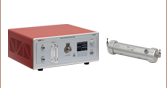
SC4500
Mid-IR Supercontinuum Laser
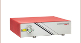
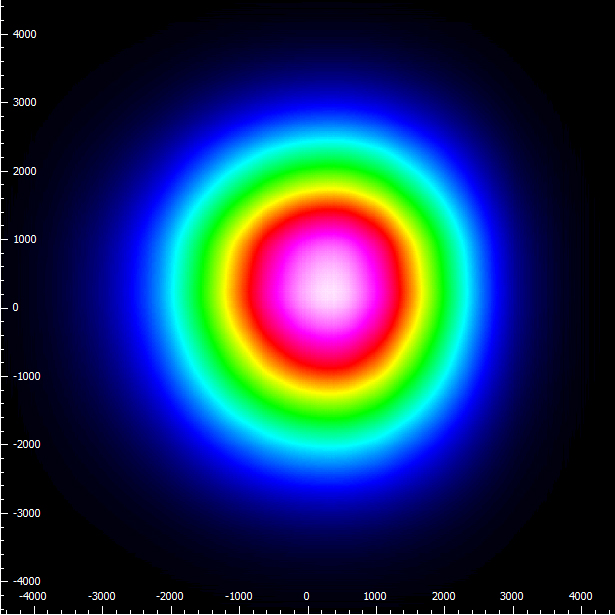
Numerical simulation of the non-linear processes used to generate the output of the SC4500 by propagation of a 2.1 µm, 100 fs, 10 nJ pulse through a dispersion-engineered InF3 fiber.


Please Wait

Click to Enlarge
Click Here for Raw Data
Figure 1.1 Typical power spectral density as a function of wavelength. The blue highlighted region denotes the operating wavelength range of 1.3 - 4.5 µm (7700 - 2200 cm-1). Please note that this is a sample spectrum and that small variations may occur from unit to unit. The fine structure seen around 2.7 μm is due to water and CO2 absorption in the beam path of the measurement setup. The sharp drop-off at 4.2 μm is also due to CO2 absorption. This spectrum was obtained without purging the laser cavity.

Reza Salem
BU Leader
Laser Systems and Technology
Need a Quote?
| Key Specifications | |
|---|---|
| Wavelength Range | 1.3 - 4.5 μm (7700 - 2200 cm-1) |
| Output Power | 300 mW (Minimum) |
| Mid-IR Output Power | 110 mW (Minimum; 2.2 - 4.2 μm) |
| Output Power Stability |
±1% (Room Temperature ±1 °C) |
| Intensity Noise | 0.025% (Typical; RMS; 10 Hz - 1 MHz) |
| Repetition Rate | 50 MHz (Typical) |
| Beam Output | Collimated; Single Spatial Mode |
| Dimensions | 17.92" x 15.89" x 5.84" (455.2 mm x 403.5 mm x 148.2 mm) |
Features
- 300 mW Output Power Over Entire Bandwidth
- >110 mW Output Power over 2.2 - 4.2 µm
- 0.025% (Typical) Intensity Noise Enables Highly Sensitive Measurements
- Femtosecond Pump Architecture to Minimize Shot-to-Shot Noise
- Robust All-Fiber Design for Hands-Off, Reliable Operation
- Record-High Brightness Enables Remote and Standoff Detection
- Compatible with Standard Fourier-Transform Infrared Spectrometers (FTIRS)
- Available with Water Cooling for Vibrationally Sensitive Applications (Contact Us)
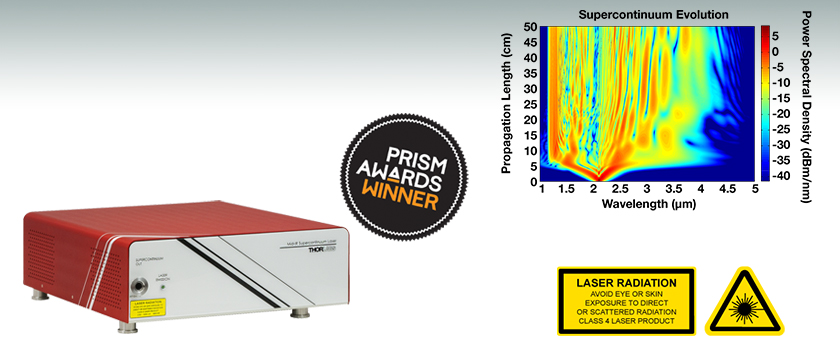
- Winner of the 2017 Prism Awards, Scientific Lasers Category
Applications
- Environmental Sensing
- Standoff Detection of Chemical and Biological Threats
- Absorption Spectroscopy with High Sensitivity
- Infrared Spectromicroscopy
- Ultrafast Spectroscopy
- Semiconductor Inspection
- Frequency Comb Spectroscopy
- Femtosecond Pulse Generation in the Mid-Infrared
- Optical Coherence Tomography (See OCT Application Tab)
The Mid-IR Supercontinuum Laser Source is the world's first commercially available femtosecond-laser-pumped source of its kind. This supercontinuum laser emits over a wavelength range from approximately 1.3 μm to 4.5 μm (7700 cm-1 to 2200 cm-1) with >300 mW of average output power in a single-mode, collimated beam. More than 110 mW of the output power is within the 2.2 - 4.2 µm
(4500 cm-1 - 2400 cm-1) range, which overlaps with many gas absorption lines and other molecular signatures. The pulsed femtosecond oscillator driving the supercontinuum runs at a fixed repetition rate of 50 MHz. The brightness of the SC4500 laser exceeds traditional Globars and even synchrotron sources by orders of magnitude.
The laser cavity can be purged via a gas inlet located in the back panel of the laser head. A gas supply connected to this inlet can cause gas to flow through the internal beam path of the laser to reduce undesirable absorption lines in the environment. This gas supply should not be pressurized. The output port of the SC4500 includes a KF16 vacuum compatible flange which can be used to connect the output to other purge capable instruments or devices.
The supercontinuum light is generated by pumping a dispersion-engineered indium fluoride (InF3) fiber with a high-power femtosecond fiber laser. Unlike supercontinuum lasers pumped in the long-pulse regime (picoseconds to nanoseconds), the spectrum of a femtosecond-pumped source is stable from pulse to pulse. As a result, our supercontinuum laser provides a typical output noise of 0.025% (RMS; 10 Hz to 1 MHz), greatly aiding applications that require high-sensitivity detection.

High brightness and low output noise make the SC4500 the ideal laser for sensing and spectroscopy applications in the mid-infrared. Applications range from environmental sensing of greenhouse gases to standoff detection in the field to spectroscopy in the lab using standard FTIR spectrometers. In addition, this laser's shot-to-shot spectral stability allows it to be used as a source of femtosecond pulses in the mid-infrared by filtering the output through a bandpass filter. An all-fiber design with proprietary fluoride-to-silica fiber splices offers robust, reliable, and maintenance-free performance.
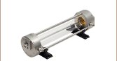
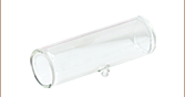
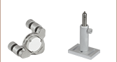
We also offer pre-assembled Herriott cells for gas absorption spectroscopy applications.
See the Publications tab for articles featuring applications of our Mid-IR Supercontinuum Laser Source. See the OCT Application tab for a novel application of this source in an optical coherence tomography system.
Click to Enlarge
Click Here for Raw Data
Figure 2.1 Typical power spectral density as a function of wavelength. Please note that this is a sample spectrum and that small variations may occur from unit to unit. The fine structure seen around 2.7 μm is due to water and CO2 absorption in the beam path of the measurement setup. The sharp drop-off at 4.2 μm is also due to CO2 absorption. This spectrum was obtained without purging the laser cavity.
Click to Enlarge
Figure 2.2 A sample measurement of the beam profile was taken at the center of the SC band (~2300 nm) using a bandpass filter with a 500 nm bandwidth. This image represents the result of a Gaussian fit which yields a 1/e2 beam diameter of 5.5 mm and a circularity of 97%.
| Item # | SC4500 | ||
|---|---|---|---|
| Parameters | Min | Typical | Max |
| Emission Center Wavelength | 1.3 - 4.5 µm (7700 - 2200 cm-1) | ||
| Output Power (Full Emission Band) | 300 mW | - | 500 mW |
| Mid-IR Output Power (2.2 - 4.2 μm) |
110 mW | - | - |
| Output Power Stability (Full Emission Band; Room Temperature ±1 °C) |
- | - | ±1% |
| Intensity Noise (RMS; 10 Hz - 1 MHz) | - | 0.025% | - |
| Repetition Rate | 48 MHz | 50 MHz | 52 MHz |
| Output Beam Diameter (1/e2; Single Mode) | - | 5.5 mm | - |
| Polarization | Random | ||
| Electrical Requirements | |||
| Input Voltage | 100 - 240 V | ||
| Frequency | 50 - 60 Hz | ||
| Power Consumption | 700 W (Max) | ||
| Environmental Requirements | |||
| Room Temperature Range | 17 °C to 25 °C | ||
| Physical Specifications | |||
| Gas Purging Inlet Connection | 0.25" (6.35 mm) Outer Diameter | ||
| Optical Output Connection | KF10/KF16 Vacuum Flange | ||
| Dimensions (Laser Head) | 17.92" x 15.89" x 5.84" (455.2 mm x 403.5 mm x 148.2 mm) |
||
| Dimensions (Controller) | 16.97" x 15.68" x 5.24" (431.0 mm x 398.2 mm x 133.1 mm) |
||


Software
Version 1.1.513.51
An installer for the Windows®-based GUI of the SC4500 MIR Supercontinuum Source.
Laser Safety and Classification
Safe practices and proper usage of safety equipment should be taken into consideration when operating lasers. The eye is susceptible to injury, even from very low levels of laser light. Thorlabs offers a range of laser safety accessories that can be used to reduce the risk of accidents or injuries. Laser emission in the visible and near infrared spectral ranges has the greatest potential for retinal injury, as the cornea and lens are transparent to those wavelengths, and the lens can focus the laser energy onto the retina.
 |
 |
 |
 |
 |
 |
 |
 |
 |
Safe Practices and Light Safety Accessories
- Laser safety eyewear must be worn whenever working with Class 3 or 4 lasers.
- Regardless of laser class, Thorlabs recommends the use of laser safety eyewear whenever working with laser beams with non-negligible powers, since metallic tools such as screwdrivers can accidentally redirect a beam.
- Laser goggles designed for specific wavelengths should be clearly available near laser setups to protect the wearer from unintentional laser reflections.
- Goggles are marked with the wavelength range over which protection is afforded and the minimum optical density within that range.
- Laser Safety Curtains and Laser Safety Fabric shield other parts of the lab from high energy lasers.
- Blackout Materials can prevent direct or reflected light from leaving the experimental setup area.
- Thorlabs' Enclosure Systems can be used to contain optical setups to isolate or minimize laser hazards.
- A fiber-pigtailed laser should always be turned off before connecting it to or disconnecting it from another fiber, especially when the laser is at power levels above 10 mW.
- All beams should be terminated at the edge of the table, and laboratory doors should be closed whenever a laser is in use.
- Do not place laser beams at eye level.
- Carry out experiments on an optical table such that all laser beams travel horizontally.
- Remove unnecessary reflective items such as reflective jewelry (e.g., rings, watches, etc.) while working near the beam path.
- Be aware that lenses and other optical devices may reflect a portion of the incident beam from the front or rear surface.
- Operate a laser at the minimum power necessary for any operation.
- If possible, reduce the output power of a laser during alignment procedures.
- Use beam shutters and filters to reduce the beam power.
- Post appropriate warning signs or labels near laser setups or rooms.
- Use a laser sign with a lightbox if operating Class 3R or 4 lasers (i.e., lasers requiring the use of a safety interlock).
- Do not use Laser Viewing Cards in place of a proper Beam Trap.
Laser Classification
Lasers are categorized into different classes according to their ability to cause eye and other damage. The International Electrotechnical Commission (IEC) is a global organization that prepares and publishes international standards for all electrical, electronic, and related technologies. The IEC document 60825-1 outlines the safety of laser products. A description of each class of laser is given below:
| Class | Description | Warning Label |
|---|---|---|
| 1 | This class of laser is safe under all conditions of normal use, including use with optical instruments for intrabeam viewing. Lasers in this class do not emit radiation at levels that may cause injury during normal operation, and therefore the maximum permissible exposure (MPE) cannot be exceeded. Class 1 lasers can also include enclosed, high-power lasers where exposure to the radiation is not possible without opening or shutting down the laser. |  |
| 1M | Class 1M lasers are safe except when used in conjunction with optical components such as telescopes and microscopes. Lasers belonging to this class emit large-diameter or divergent beams, and the MPE cannot normally be exceeded unless focusing or imaging optics are used to narrow the beam. However, if the beam is refocused, the hazard may be increased and the class may be changed accordingly. |  |
| 2 | Class 2 lasers, which are limited to 1 mW of visible continuous-wave radiation, are safe because the blink reflex will limit the exposure in the eye to 0.25 seconds. This category only applies to visible radiation (400 - 700 nm). |  |
| 2M | Because of the blink reflex, this class of laser is classified as safe as long as the beam is not viewed through optical instruments. This laser class also applies to larger-diameter or diverging laser beams. |  |
| 3R | Class 3R lasers produce visible and invisible light that is hazardous under direct and specular-reflection viewing conditions. Eye injuries may occur if you directly view the beam, especially when using optical instruments. Lasers in this class are considered safe as long as they are handled with restricted beam viewing. The MPE can be exceeded with this class of laser; however, this presents a low risk level to injury. Visible, continuous-wave lasers in this class are limited to 5 mW of output power. |  |
| 3B | Class 3B lasers are hazardous to the eye if exposed directly. Diffuse reflections are usually not harmful, but may be when using higher-power Class 3B lasers. Safe handling of devices in this class includes wearing protective eyewear where direct viewing of the laser beam may occur. Lasers of this class must be equipped with a key switch and a safety interlock; moreover, laser safety signs should be used, such that the laser cannot be used without the safety light turning on. Laser products with power output near the upper range of Class 3B may also cause skin burns. |  |
| 4 | This class of laser may cause damage to the skin, and also to the eye, even from the viewing of diffuse reflections. These hazards may also apply to indirect or non-specular reflections of the beam, even from apparently matte surfaces. Great care must be taken when handling these lasers. They also represent a fire risk, because they may ignite combustible material. Class 4 lasers must be equipped with a key switch and a safety interlock. |  |
| All class 2 lasers (and higher) must display, in addition to the corresponding sign above, this triangular warning sign. |  |
|
Pulsed Laser Emission: Power and Energy Calculations

Determining whether emission from a pulsed laser is compatible with a device or application can require referencing parameters that are not supplied by the laser's manufacturer. When this is the case, the necessary parameters can typically be calculated from the available information. Calculating peak pulse power, average power, pulse energy, and related parameters can be necessary to achieve desired outcomes including:
- Protecting biological samples from harm.
- Measuring the pulsed laser emission without damaging photodetectors and other sensors.
- Exciting fluorescence and non-linear effects in materials.
Pulsed laser radiation parameters are illustrated in Figure 170A and described in Table 170B. For quick reference, a list of equations is provided below. The document available for download provides this information, as well as an introduction to pulsed laser emission, an overview of relationships among the different parameters, and guidance for applying the calculations.
|
Equations: |
||||
 |
and |  |
||
 |
||||
 |
||||
 |
||||
Peak power and average power calculated from each other: |
||||
 |
and |  |
||
| Peak power calculated from average power and duty cycle*: | ||||
 |
*Duty cycle ( ) is the fraction of time during which there is laser pulse emission. ) is the fraction of time during which there is laser pulse emission. |
|||
Click to Enlarge
Figure 170A Parameters used to describe pulsed laser emission are indicated in this plot and described in Table 170B. Pulse energy (E) is the shaded area under the pulse curve. Pulse energy is, equivalently, the area of the diagonally hashed region.
| Table 170B Pulse Parameters | |||||
|---|---|---|---|---|---|
| Parameter | Symbol | Units | Description | ||
| Pulse Energy | E | Joules [J] | A measure of one pulse's total emission, which is the only light emitted by the laser over the entire period. The pulse energy equals the shaded area, which is equivalent to the area covered by diagonal hash marks. | ||
| Period | Δt | Seconds [s] | The amount of time between the start of one pulse and the start of the next. | ||
| Average Power | Pavg | Watts [W] | The height on the optical power axis, if the energy emitted by the pulse were uniformly spread over the entire period. | ||
| Instantaneous Power | P | Watts [W] | The optical power at a single, specific point in time. | ||
| Peak Power | Ppeak | Watts [W] | The maximum instantaneous optical power output by the laser. | ||
| Pulse Width |  |
Seconds [s] | A measure of the time between the beginning and end of the pulse, typically based on the full width half maximum (FWHM) of the pulse shape. Also called pulse duration. | ||
| Repetition Rate | frep | Hertz [Hz] | The frequency with which pulses are emitted. Equal to the reciprocal of the period. | ||
Example Calculation:
Is it safe to use a detector with a specified maximum peak optical input power of 75 mW to measure the following pulsed laser emission?
- Average Power: 1 mW
- Repetition Rate: 85 MHz
- Pulse Width: 10 fs
The energy per pulse:

seems low, but the peak pulse power is:

It is not safe to use the detector to measure this pulsed laser emission, since the peak power of the pulses is >5 orders of magnitude higher than the detector's maximum peak optical input power.
Selected Publications Featuring Thorlabs' Mid-IR Supercontinuum Laser
2022
Zorin I, Gattinger P, Ebner A, and Brandstetter M. "Advances in mid-infrared spectroscopy enabled by supercontinuum laser sources," Opt. Express. 2022; 30, 5222-5254.
2021
Meem M, Majumder A, Banerji S, et al. "Imaging from the visible to the longwave infrared wavelengths via an inverse-designed flat lens," Opt. Express. 2021; 29, 20715-20723.
Salem R, "Mid-IR supercontinuum laser covers key spectral bands for spectroscopy," Laser Focus World. 2021; 57(04), 48–50.
Salem R, Backus S, Liu D, et al. "5-11 μm Supercontinuum Generation Using Cascaded Nonlinearities in Fluoride Fiber and ZGP," Conference on Lasers and Electro-Optics. 2021; OSA Technical Digest (Optica Publishing Group, 2021), paper STh1L.5.
2019
Wang Q, Jing JY, Wang BT. "Highly Sensitive SPR Biosensor Based on Graphene Oxide and Staphylococcal Protein A Co-Modified TFBG for Human IgG Detection," IEEE Transactions on Instrumentation and Measurement. Sept. 2019; 68(9), 3350-3357.
2015
Salem R, Jiang Z, Liu D, et al. "Mid-infrared supercontinuum generation spanning 1.8 octaves using step-index indium fluoride fiber pumped by a femtosecond fiber laser near 2 µm," Opt. Express. 2015 Nov 16; 23 (24): 30592 - 30602.

Click to Enlarge
Figure 7.1 OCT scans recorded: (a) B-scan of 300 μm thick sintered alumina sheet (1% porosity), scan length 8 mm; (b) B-scan of 450 μm thick sintered alumina sheet with embossed microchannels (1% porosity), scan length 8 mm; (c) B-scan of high-porous (2%) and high-roughness 3D printed ceramic alumina sample (325 μm thick), scan length 8 mm; (d) volume scan (4x8 mm2 area) of a green LCM part [650 μm thick, corresponds to the printed part shown in (c)], consists of ceramic particles embedded in a polymer matrix; (e) En-face scan of the back interface, retrieved from (d).
Images Courtesy of Ivan Zorin and Bettina Heise, Optical Coherence Tomography Group,
Research Center for Non-Destructive Testing GmbH, Linz, Austria
Mid-IR OCT Imaging
Optical Coherence Tomography (OCT) is a noninvasive optical imaging technique that provides real-time 3D images with micron-scale resolution and at MHz repetition rates. In this white paper by Ivan Zorin and Bettina Heise of the Research Center for Non-Destructive Testing GmbH (RECENDT), the authors demonstrate the performance of Thorlabs' SC4500 Supercontinuum Laser as a light source in their OCT system. They propose this use of a mid-IR OCT system as an alternative to existing near-IR systems, which are more limited by scattering.
Figure 7.1, provided by the authors, shows scans of various samples, including highly scattering samples made by lithography-based ceramic manufacturing (LCM) which cannot be imaged by commercial near-IR OCT systems.
| Posted Comments: | |
user
(posted 2023-08-10 17:17:44.757) Also, what is the typical beam divergence? - thank you cdolbashian
(posted 2023-09-11 02:05:47.0) Thank you for reaching out to us with this inquiry. The typical beam divergence is <0.4mrad, Daniel Korwan
(posted 2023-08-10 15:59:34.837) Have you determined what the pulse length and energy per pulse yet (I see the comment on the simulated pulse length of 200-300fs)? -thank you cdolbashian
(posted 2023-09-11 02:05:47.0) Thank you for reaching out to us with this inquiry Daniel. We still estimate the pulse duration to be ~200-300fs, while the pulse energy is >5nJ. The difficulty of measuring the pulse duration directly stems from the broadband nature of the source. user
(posted 2022-04-25 01:36:16.283) What's the pulse width (in time) and pulse-to-pulse timing jitter of this laser? jdelia
(posted 2022-04-27 09:33:56.0) Thank you for contacting Thorlabs. The integrated FSL1950 pump laser in the SC4500 is sub 100 fs. These pulses undergo nonlinear spectral broadening, which broadens their spectrum and also alters the pulse width and shape. The dispersion in the nonlinear fiber is relatively small and flat over the continuum so we don't expect extensive broadening. We have numerical simulations that suggest the output pulses of the SC4500 should be on the order of 200 - 300 fs. While we do not specify a pulse-to-pulse jitter for this product, the seed oscillator is a passively mode-locked fiber oscillator so there is no reason to expect large jitter. There will be some rep rate drift which will depend on the cavity length variation (i.e. environmental temperature). For a few ten MHz rep rate ML fiber laser, the cavity length is meter scale, and the cavity length variation should be much less than 1% of the cavity length. Therefore, we would expect the max rep rate drift to be in the kHz range or less. Arindam Banerjee
(posted 2020-03-05 01:23:20.507) We are distrobutors of Thorlabs in India.
A request from customer for quotation.
the application is to characterize Infrared detectors (HgCdTe and InGaAs based). the SC4500 will be used as photon source covering MWIR range. Also this unit will be used for spectral characterization of infrared optical filters as part of an optical test setup llamb
(posted 2020-03-05 11:27:28.0) Thank you for contacting Thorlabs. A representative will reach out to you directly to discuss your application and provide a quote. agoncharov
(posted 2017-10-28 20:50:38.837) please provide price and ordering information
202 478 8947
Alex tfrisch
(posted 2017-10-30 10:28:59.0) Hello, thank you for contacting Thorlabs. We will reach out to you with a quote. |