 Products Home / Imaging Components / DIY Cerna Components: Imaging for Home Builders / Widefield Viewing Modules for DIY Cerna® Systems
Widefield Viewing Modules for DIY Cerna® Systems

- Trinoculars for Viewing Samples via Naked Eye
- Camera Tubes and Double Camera Ports for Camera Attachment
- Breadboards and Dovetail Adapters for Custom Assemblies
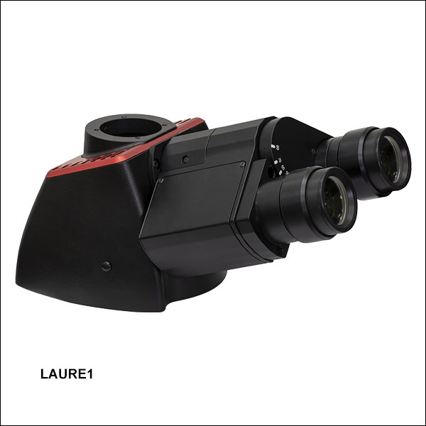
LAURE1
Trinoculars with
10X Eyepieces
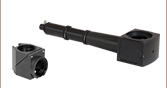
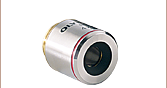
WFA4101
0.75X Camera Tube
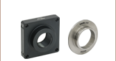
CSD1002
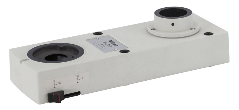
Fixed Magnification Double Camera Port
Application Idea
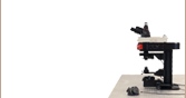
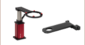
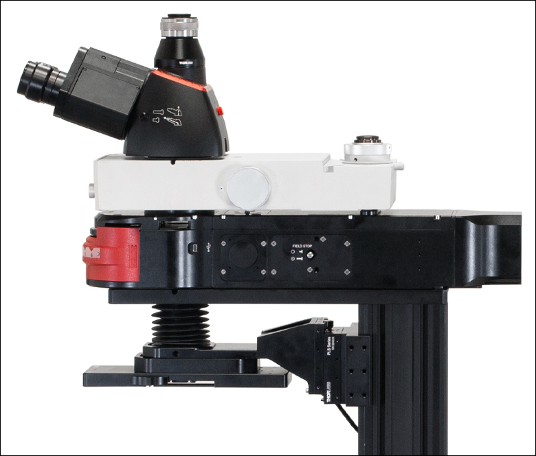
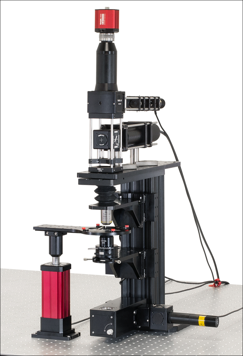
User-Built Epi-Illumination and Widefield Module Using a Breadboard Top, Dovetail Adapters, and Thorlabs' Optomechanics
CSA1003
D1N Dovetail Adapter with 60 mm Cage Mounting Holes


Please Wait
Click to Enlarge
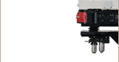
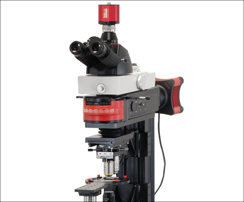
Figure 1.1 Trinoculars with 10X Eyepieces and Camera Mounted on a 1X Camera Tube for Imaging an Epi-Illuminated Sample

Did You Know?
Multiple optical elements, including the microscope objective, tube lens, and eyepieces, together define the magnification of a system. See the Magnification & FOV tab to learn more.
Features
Trinoculars with 10X Eyepieces and a Camera Port- Camera Tubes Mechanically Align a Camera at the Image Plane with 1X, 0.75X, or 0.5X Magnification
- Double Camera Ports Allow Two Cameras to be Attached Simultaneously
- Breadboards and Dovetail Adapters for Creating Custom Widefield Assemblies Using Thorlabs Cage Systems and SM-Threaded Lens Tubes
These widefield viewing accessories allow images obtained from a sample to be viewed and recorded.
Upright
Thorlabs also separately offers the eyepiece and IR blocking filter included in the LAURE1 trinoculars. The eyepiece provides 10X magnification, while the filter transmits wavelengths from 375 nm to 650 nm and blocks wavelength from 700 nm to 1400 nm. An eyepiece adapter is also available for connecting custom image detection setups to either eyepiece of the trinoculars. This adapter features internal SM1 (1.035"-40) threading for Ø1" lens tubes, external SM2 (2.035"-40) threading for Ø2" lens tubes, and four 4-40 tapped holes for 30 mm cage systems.
Camera Tubes
Camera tubes are designed to place the camera at the focal plane of the system's tube lens, thus allowing the camera to image the FOV on the sensor. They can be
Double Camera Ports
Double camera ports allow for the simultaneous attachment of up to two cameras or a trinocular onto a microscope system, thus allowing for greater experimental flexibility. They are available with or without included optics to direct light to separate, independently configurable cameras.
Breadboard Tops
Breadboards have an array of 1/4"-20 mounting taps to provide the means to construct custom-designed widefield viewing apparatuses and epi-illumination pathways on top of a DIY Cerna® microscope body. They are available in two sizes: 14.00" x 11.00" and 18.00" x 4.60" (350.0 mm x 275.0 mm and 450.0 mm x 116.8 mm for metric versions). The larger version provides a larger work surface with more mounting taps while the smaller version does not restrict approach angles. The small version also has eight 4-40 taps around the Ø1.5" through hole for 30 mm and 60 mm cage systems.
Dovetail Adapters
Dovetail interfaces are used to facilitate the attachment of many DIY Cerna modules, including the widefield viewing components below. Various dovetail adapters are provided to adapt Thorlabs' Cerna assemblies to standard Thorlabs optomechanical systems, such as SM-threaded lens tubes, 30 mm cage systems, and 60 mm cage systems. Please see the Microscope Dovetails tab for more information on the type of dovetail mounts used and their specifications, and the DIY Cerna Interfaces tab for a comprehensive compatibility table for the Cerna product line.
| Table 76C Thorlabs Dovetail Referencea | |||
|---|---|---|---|
| Type | Shape | Outer Dimension | Angle |
| 95 mm | Linear | 95 mm | 45° |
| D1N | Circular | Ø2.018" | 60° |
| D2Nb | Circular | Ø1.50" | 90° |
| D2NBb | Circular | Ø1.50" | 90° |
| D3N | Circular | Ø45 mm | 70° |
| D5N | Circular | Ø1.58" | 90° |
| D6N | Circular | Ø1.90" | 90° |
| D7N | Circular | Ø2.05" | 90° |
| D8N | Circular | Ø40 mm | 90° |
| D9N | Circular | Ø50 mm | 90° |
| D10N | Circular | Ø52 mm | 90° |
| D1T | Circular | Ø1.50" | 60° |
| D3T | Circular | Ø1.65" | 90° |
| D4T | Circular | Ø1.20" | 90° |
| D1Y | Circular | Ø107 mm | 60° |
| D2Y | Circular | Ø2.32" | 50° |
| D3Y | Circular | Ø1.75" | 90° |
| D4Y | Circular | Ø56 mm | 60° |
| D5Y | Circular | Ø46 mm | 60° |
| D6Y | Circular | Ø41.9 mm | 45° |
| D1Z | Circular | Ø54 mm | 60° |
| D2Z | Circular | Ø57 mm | 60° |
| D3Z | Circular | Ø54 mm | 45° |
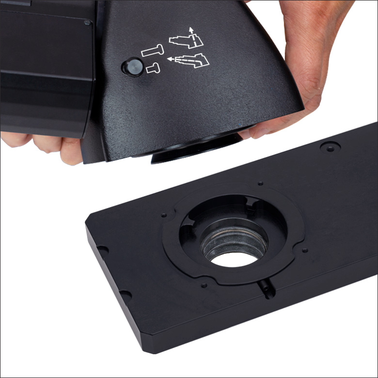
Click to Enlarge
Figure 76B This photo shows the male D1N dovetail on the trinoculars next to the female D1N dovetail on the epi-illumination arm.

Click to Enlarge
Figure 76A This photo shows the male 95 mm dovetail on the microscope body and the female 95 mm dovetail on the CSA1002 Fixed Arm.
Introduction to Microscope Dovetails
Dovetails are used for mechanical mating and optical port alignment of microscope components. Components are connected by inserting one dovetail into another, then tightening one or more locking setscrews on the female dovetail. Dovetails come in two shapes: linear and circular. Linear dovetails allow the mating components to slide before being locked down, providing flexible positioning options while limiting unneeded degrees of freedom. Circular dovetails align optical ports on different components, maintaining a single optical axis with minimal user intervention.
Thorlabs manufactures many components which use dovetails to mate with our own components or those of other manufacturers. To make it easier to identify dovetail compatibility, we have developed a set of dovetail designations. The naming convention of these designations is used only by Thorlabs and not other microscope manufacturers. Table 76C lists all the dovetails Thorlabs makes, along with their key dimensions.
In the case of Thorlabs’ Cerna® microscopes, different dovetail types are used on different sections of the microscope to ensure that only compatible components can be mated. For example, our WFA2002 Epi-Illuminator Module has a male D1N dovetail that mates with the female D1N dovetail on the microscope body's epi-illumination arm, while the CSS2001 XY Microscopy Stage has a female D1Y dovetail that mates with the male D1Y dovetail on the CSA1051 Mounting Arm.
To learn which dovetail type(s) are on a particular component, consult its mechanical drawing, available by clicking on the red Docs icon ( ) below. For adapters with a female dovetail, the drawing also indicates the size of the hex key needed for the locking setscrew(s). It is important to note that mechanical compatibility does not ensure optical compatibility. Information on optical compatibility is available from Thorlabs' web presentations.
For customers interested in machining their own dovetails, Table 76C gives the outer diameter and angle (as defined by Figures 76D and 76E) of each Thorlabs dovetail designation. However, the dovetail's height must be determined by the user, and for circular dovetails, the user must also determine the inner diameter and bore diameter. These quantities can vary for dovetails of the same type. One can use the intended mating part to verify compatibility.
In order to reduce wear and simplify connections, dovetails are often machined with chamfers, recesses, and other mechanical features. Some examples of these variations are shown by Figures 76D and 76E.

Click to Enlarge
Figure 76D Two examples of how circular male dovetails can be manufactured.
Click to Enlarge
Figure 76E Two examples of how circular female dovetails can be manufactured.
Figure 73A When viewing an image with a camera, the system magnification is the product of the objective and camera tube magnifications. When viewing an image with trinoculars, the system magnification is the product of the objective and eyepiece magnifications.

| Table 73B Focal Lengths by Manufacturer | |
|---|---|
| Manufacturer | Tube Lens Focal Length |
| Leica | f = 200 mm |
| Mitutoyo | f = 200 mm |
| Nikon | f = 200 mm |
| Olympus | f = 180 mm |
| Thorlabs | f = 200 mm |
| Zeiss | f = 165 mm |
Magnification and Sample Area Calculations
Magnification
The magnification of a system is the multiplicative product of the magnification of each optical element in the system. Optical elements that produce magnification include objectives, camera tubes, and trinocular eyepieces, as shown in Figure 73A. It is important to note that the magnification quoted in these products' specifications is usually only valid when all optical elements are made by the same manufacturer. If this is not the case, then the magnification of the system can still be calculated, but an effective objective magnification should be calculated first, as described below.
To adapt the examples shown here to your own microscope, please use our Magnification and FOV Calculator, which is available for download by clicking on the Magnification and FOV Calculator button. Note the calculator is an Excel spreadsheet that uses macros. In order to use the calculator, macros must be enabled. To enable macros, click the "Enable Content" button in the yellow message bar upon opening the file.
Example 1: Camera Magnification
When imaging a sample with a camera, the image is magnified by the objective and the camera tube. If using a 20X Nikon objective and a 0.75X Nikon camera tube, then the image at the camera has 20X × 0.75X = 15X magnification.
Example 2: Trinocular Magnification
When imaging a sample through trinoculars, the image is magnified by the objective and the eyepieces in the trinoculars. If using a 20X Nikon objective and Nikon trinoculars with 10X eyepieces, then the image at the eyepieces has 20X × 10X = 200X magnification. Note that the image at the eyepieces does not pass through the camera tube, as shown by Figure 73A.
Using an Objective with a Microscope from a Different Manufacturer
Magnification is not a fundamental value: it is a derived value, calculated by assuming a specific tube lens focal length. Each microscope manufacturer has adopted a different focal length for their tube lens, as shown by Table 73B. Hence, when combining optical elements from different manufacturers, it is necessary to calculate an effective magnification for the objective, which is then used to calculate the magnification of the system.
The effective magnification of an objective is given by Equation 1:

Here, the Design Magnification is the magnification printed on the objective, fTube Lens in Microscope is the focal length of the tube lens in the microscope you are using, and fDesign Tube Lens of Objective is the tube lens focal length that the objective manufacturer used to calculate the Design Magnification. These focal lengths are given by Table 73B.
Note that Leica, Mitutoyo, Nikon, and Thorlabs use the same tube lens focal length; if combining elements from any of these manufacturers, no conversion is needed. Once the effective objective magnification is calculated, the magnification of the system can be calculated as before.
Example 3: Trinocular Magnification (Different Manufacturers)
When imaging a sample through trinoculars, the image is magnified by the objective and the eyepieces in the trinoculars. This example will use a 20X Olympus objective and Nikon trinoculars with 10X eyepieces.
Following Equation 1 and Table 73B, we calculate the effective magnification of an Olympus objective in a Nikon microscope:

The effective magnification of the Olympus objective is 22.2X and the trinoculars have 10X eyepieces, so the image at the eyepieces has 22.2X × 10X = 222X magnification.
 Figure 73C Sample Area When Imaged on a Camera
Sample Area When Imaged on a Camera
When imaging a sample with a camera, the dimensions of the sample area are determined by the dimensions of the camera sensor and the system magnification, as shown by Equation 2.

The camera sensor dimensions can be obtained from the manufacturer, while the system magnification is the multiplicative product of the objective magnification and the camera tube magnification (see Example 1). If needed, the objective magnification can be adjusted as shown in Example 3.
As the magnification increases, the resolution improves, but the field of view also decreases. The dependence of the field of view on magnification is shown in Figure 73C.
Example 4: Sample Area
The dimensions of the camera sensor in Thorlabs' previous-generation 1501M-USB Scientific Camera are 8.98 mm × 6.71 mm. If this camera is used with the Nikon objective and trinoculars from Example 1, which have a system magnification of 15X, then the image area is:

Sample Area Examples
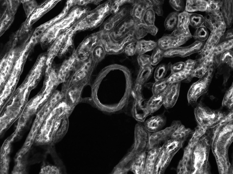
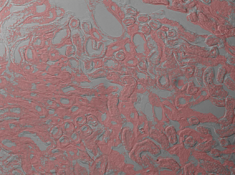
Figures 73D through 73F, images of a mouse kidney, were all acquired using the same objective and the same camera. However, the camera tubes used were different. Figures 73D through 73F demonstrate that decreasing the camera tube magnification enlarges the field of view at the expense of the size of the details in the image.


Standard Mechanical Interfaces on DIY Cerna® Components
The table below gives the dovetail, optical component threads, and cage system interfaces that are present on each DIY Cerna component. If a DIY Cerna component does not have one of the standard interfaces in the table, it is not listed here. Please note that mechanical compatibility does not ensure optical compatibility. Information on optical compatibility is available from Thorlabs' web presentations.
| Item # | Microscope Dovetails | Optical Component Threadsa | Cage Systemsb | ||||||||||
|---|---|---|---|---|---|---|---|---|---|---|---|---|---|
| 95 mm | D1N | D2N | D2NB | D3N | D5N | D1T | D3T | D1Y | D5Y | Internal | External | ||
| 2CM1 | - | - | - | - | - | - | - | - | - | - | SM1c (1.035"-40) and SM2d (2.035"-40) | SM1c (1.035"-40) | 60 mmd |
| 2CM2 | - | - | - | - | - | - | - | - | - | - | SM1c (1.035"-40) and SM2d (2.035"-40) | SM1c (1.035"-40) | 30 mmc |
| BSA2000e | - | - | - | - | Female | - | - | - | - | - | - | - | - |
| CEA1350 | Male | Female | - | - | - | - | - | - | - | - | - | - | 60 mmd |
| CEA1400 | Male | Female | - | - | - | - | - | - | - | - | - | - | 60 mmd |
| CEA1500 | Male | Female | - | - | - | - | - | - | - | - | - | - | 60 mmd |
| CEA1600 | Male | Female | - | - | - | - | - | - | - | - | - | - | 60 mmd |
| CFB1500 | Male | - | - | - | - | - | - | - | - | - | - | - | - |
| CSA1000 | Female | - | - | - | - | - | - | - | - | - | - | - | - |
| CSA1001 | Female | - | - | - | - | - | - | - | - | - | SM1c (1.035"-40) | - | 30 mmc |
| CSA1002 | Female | - | - | - | - | - | - | - | - | - | SM2d (2.035"-40) | - | 60 mmd |
| CSA1003 | - | Female | - | - | - | - | - | - | - | - | - | - | 60 mmd |
| CSA1051 | Female | - | - | - | - | - | - | - | Male | - | - | - | - |
| CSA1200e,f | - | - | - | - | - | - | - | - | - | - | - | - | 60 mmd |
| CSA1400e | - | - | - | - | - | - | Female | - | - | - | - | - | 60 mmd |
| CSA1500e,g | - | - | - | - | - | - | - | - | - | - | - | - | - |
| CSA2000e | - | - | - | - | Female | - | - | - | - | - | SM2d (2.035"-40) | - | 60 mmd |
| CSA2001 | - | - | - | - | Female | - | - | - | - | - | - | SM2d (2.035"-40) | - |
| CSA2100e | - | - | - | - | - | - | - | - | - | - | SM2d (2.035"-40) | - | 60 mmd |
| CSA3000(/M) | - | Male | - | - | - | - | - | - | - | - | - | - | 30 mmc and 60 mmd |
| CSA3010(/M) | - | Male | - | - | - | - | - | - | - | - | - | - | 30 mmc and 60 mmd |
| Item # | 95 mm | D1N | D2N | D2NB | D3N | D5N | D1T | D3T | D1Y | D5Y | Internal | External | Cage Systems |
| CSC1001 | - | - | - | - | Male | - | - | - | - | - | - | - | - |
| CSC1002 | - | - | - | - | Male | - | - | - | - | - | - | - | - |
| CSC2001 | - | - | - | - | Male | - | - | - | - | - | - | - | - |
| CSD1001 | - | Male & Female | - | Female | - | - | - | - | - | - | - | - | - |
| CSD1002 | - | Male & Female | - | - | - | - | - | - | - | - | - | C-Mounth | - |
| CSE2000 | - | Male & Female | - | - | - | - | - | - | - | - | - | - | 60 mmd |
| CSE2100 | - | Male & Female | - | - | - | - | - | Female | - | - | SM1c (1.035"-40) | - | 30 mmc and 60 mmd |
| CSE2200 | - | Male & Female | - | - | - | - | - | Female | - | - | SM1c (1.035"-40) | - | 30 mmc and 60 mmd |
| CSN100e | - | - | - | - | - | - | - | - | - | - | M32 x 0.75 | - | 60 mmd |
| CSN110 | - | - | - | - | - | - | Male | - | - | - | M32 x 0.75 | - | 30 mmc and 60 mmd |
| CSNK10 | - | - | - | - | - | - | - | - | - | - | M32 x 0.75 | - | 60 mmd |
| CSNK100e | - | - | - | - | - | - | - | - | - | - | M32 x 0.75 | - | 60 mmd |
| CSN200 | - | - | - | - | - | - | Male | - | - | - | M32 x 0.75 | - | - |
| CSN210 | - | - | - | - | - | - | Male | - | - | - | M32 x 0.75 | - | - |
| CSN500 | - | - | - | - | - | - | Male | - | - | - | M25 x 0.75 | - | - |
| CSN510 | - | - | - | - | - | - | Male | - | - | - | RMS (0.800"-36) | - | - |
| CSN1201f | - | - | - | - | - | - | - | - | - | - | M32 x 0.75 | - | - |
| CSN1202f | - | - | - | - | - | - | - | - | - | - | M25 x 0.75 | - | - |
| CSS2001 | - | - | - | - | - | - | - | - | Female | - | - | - | - |
| LAURE1 | - | Male | Female | - | - | - | - | - | - | - | - | - | - |
| LAURE2 | - | Male | Female | - | - | - | - | - | - | - | - | - | - |
| LCPN1 | - | - | - | - | Male | - | - | - | - | - | SM30 (M30.5 x 0.5) | - | 30 mmc and 60 mmd |
| LCPN2 | - | Male | - | - | - | - | - | - | - | - | SM30 (M30.5 x 0.5) | - | 30 mmc and 60 mmd |
| Item # | 95 mm | D1N | D2N | D2NB | D3N | D5N | D1T | D3T | D1Y | D5Y | Internal | External | Cage Systems |
| LCPN3 | - | Male | - | - | - | - | - | - | - | Female | SM30 (M30.5 x 0.5) | - | 60 mmd |
| LCPN4 | - | Male | - | - | - | - | - | - | - | - | SM2d (2.035"-40) | - | 60 mmd |
| LCPN5 | - | - | - | - | Male | - | - | - | - | - | SM2d (2.035"-40) | - | 60 mmd |
| LCPN6 | - | - | Female | - | - | - | - | - | - | - | SM1c (1.035"-40) | - | 30 mmc and 60 mmd |
| LCPY2 | - | - | - | - | - | - | - | - | - | Male | SM30 (M30.5 x 0.5) | - | 30 mmc and 60 mmd |
| LCPY3 | - | - | - | - | - | - | - | - | - | Female | - | - | 30 mmc and 60 mmd |
| OPX2400(/M) | - | Male & Female | - | - | - | - | - | - | - | - | SM2d (2.035"-40) | - | 60 mmd |
| SM1A70 | - | - | - | - | - | - | - | - | - | - | SM30 (M30.5 x 0.5) | SM1c (1.035"-40) | - |
| SM1A58 | - | - | Male | Male | - | - | - | - | - | - | SM1c (1.035"-40) | SM2d (2.035"-40) | 30 mmc |
| SM2A56 | - | - | - | - | - | - | - | Male | - | - | - | SM2d (2.035"-40) | - |
| SM2A59 | - | Male | - | - | - | - | - | - | - | - | SM2d (2.035"-40) | - | - |
| TC1X | - | - | Male | - | - | - | - | - | - | - | - | - | - |
| WFA0150 | Female | - | - | - | - | - | - | - | - | - | - | - | - |
| WFA1000 | - | - | - | - | - | - | - | - | - | - | - | - | 30 mmc |
| WFA1010 | - | - | - | - | - | - | - | - | - | - | SM1c (1.035"-40) | - | 30 mmc |
| WFA1020 | - | - | - | - | - | - | - | - | - | - | SM1c (1.035"-40) | - | 30 mmc |
| WFA1051 | - | - | - | - | - | - | - | - | - | - | SM1c (1.035"-40) | - | 30 mmc |
| WFA1100 | - | - | - | - | - | - | - | - | - | - | - | - | 30 mmc |
| WFA2001 | - | Male & Female | - | - | - | - | - | - | - | - | SM1c (1.035"-40) | SM1c (1.035"-40) | - |
| WFA2002 | - | Male & Female | - | - | - | - | - | - | - | - | SM1c (1.035"-40) | - | 30 mmc |
| Item # | 95 mm | D1N | D2N | D2NB | D3N | D5N | D1T | D3T | D1Y | D5Y | Internal | External | Cage Systems |
| WFA4100 | - | Male | - | - | - | - | - | - | - | - | SM1c (1.035"-40) | C-Mounth | - |
| WFA4101 | - | Male | - | - | - | - | - | - | - | - | SM1c (1.035"-40) | C-Mounth | - |
| WFA4102 | - | Male | - | - | - | - | - | - | - | - | SM1c (1.035"-40) | C-Mounth | - |
| WFA4111 | - | Male | - | - | - | - | - | - | - | - | - | SM2d (2.035"-40) | - |
| WFA4112 | - | - | - | Male | - | - | - | - | - | - | - | C-Mounth | - |
| Female | - | - | - | - | - | - | - | - | - | - | - | - | |
| Female | - | - | - | - | - | - | - | - | - | - | - | - | |
| Female | - | - | - | - | - | - | - | - | - | - | - | - | |
| Female | - | - | - | - | - | - | - | - | - | - | - | - | |
| XT95P12(/M) | Female | - | - | - | - | - | - | - | - | - | - | - | - |
| ZFM1020 | Female | - | - | - | - | - | - | - | - | - | - | - | - |
| ZFM1030 | Female | - | - | - | - | - | - | - | - | - | - | - | - |
| ZFM2020 | Female | - | - | - | - | - | - | - | - | - | - | - | - |
| ZFM2030 | Female | - | - | - | - | - | - | - | - | - | - | - | - |
Building a Cerna® Microscope
The Cerna microscopy platform's large working volume and system of dovetails make it straightforward to connect and position the components of the microscope. This flexibility enables simple and stable set up of a preconfigured microscope, and provides easy paths for later upgrades and modification. See the videos in this tab for a couple of examples of the assembly of some DIY Cerna microscopes.
DIY Cerna Design and Assembly
Video 20A Walkthrough of a DIY Microscope Configuration
This DIY microscope uses a CSA3000(/M) Breadboard Top, a CSA2001 Dovetail Adapter, our CSA1001 and CSA1002 Fixed Arms, and other body attachments and extensions. These components provide interfaces to our lens tube and cage construction systems, allowing the rig to incorporate two independent trans-illumination modules, a home-built epi-illumination path, and a custom sample viewing optical path.
The simplicity of Thorlabs optomechanical interfaces allows a custom DIY microscope to be quickly assembled and reconfigured for custom imaging applications.
| Posted Comments: | |
Masayuki Futamata
(posted 2025-01-09 16:02:53.177) 時々説明に出てくる、視野と倍率のタブがどこになるのか不明です。 cdolbashian
(posted 2025-01-10 12:13:13.0) Thank you for reaching out to us with this inquiry. You are inquiring about where we have our "Magnification and FOV" tab on the product page, as we reference it in a few different spots on the same page. It is the 3rd tab towards the top of the page, directly below the main banner image on the page. I have contacted directly in order to more easily guide you there. Alex B
(posted 2023-08-14 20:20:17.163) Hi, can you advise as to whether the tube lens for the WFA4100 works out to 1200nm? I can't appear to find the part number/transmittance data for the included optic.
I am adapting a SFM/SFM2 based system to also be capable of NIR imaging and would like to know if this requires changing. jdelia
(posted 2025-11-05 11:14:09.0) Thank you for contacting Thorlabs. The component tube lens inside is a TTL200, which is our in-house visible-wavelength tube lens. While it would technically work in the IR, we would expect a decent amount of attenuation and some degree of focal shift: https://www.thorlabs.com/images/TabImages/TTL200_Transmission_G1-780.gif. Note that the transmission graph has a blue shaded region where we guarantee a transmission value. Outside of that region, we cannot necessarily guarantee the posted transmission. For the focal shift, I would encourage you to check out the specs tab of the TTL200 (https://www.thorlabs.com/newgrouppage9.cfm?objectgroup_id=5834&pn=TTL200&tabname=Specs) and click the various graphs, read the captions, and supporting footnotes. user
(posted 2023-06-08 03:32:08.457) Are items #WFA4102 and #TTL100-A the same in optical features? cdolbashian
(posted 2023-06-12 02:00:30.0) Thank you for reaching out to us with this inquiry. The part featured in the WFA4102 is listed as an achromatic doublet with 100mm EFL. For the TTL100-A, we actually employ more optical elements in order to improve performance by further minimizing optical aberrations. user
(posted 2020-03-23 13:21:31.08) Is it possible to have CSD1002 using gold mirror that will allow the microscope to be used in IR range? YLohia
(posted 2020-03-23 02:27:38.0) Hello, thank you for contacting Thorlabs. Custom items can be requested by emailing techsupport@thorlabs.com. We will reach out to you directly to discuss this customization. David Carr
(posted 2019-10-20 22:23:09.297) You should consider correcting the note for the new eyepieces. You state that "The eyepiece features an adjustable focus that allows users to rotate the housing while not rotating the optics inside." Unless someone changed the design within the past 4 months, you are confusing this feature with one that is on the trinoc (LAUREx). The trinoc has a feature that allows the interpupilary distance to be adjusted without the right eyepiece rotating. This allows a user who has a reticle in the right eyepiece to adjust the interpupilary distance, and not have the reticle rotate relative to the sample they are viewing. YLohia
(posted 2019-11-14 09:31:42.0) The eyepiece has a rotatable barrel that changes the distance of optics, thus allowing you to focus so you can see the image more clearly. I believe you are referring to the adjustment on the trinoc to adjust the distance between two eyepiece to match the inter pupil distance of your eyes. We will reach out to you directly to discuss this further. |
Click on the different parts of the microscope to explore their functions.
Elements of a Microscope
This overview was developed to provide a general understanding of a Cerna® microscope. Click on the different portions of the microscope in Figure 77A or use the links below to learn how a Cerna microscope visualizes a sample.
Terminology
Arm: Holds components in the optical path of the microscope.
Bayonet Mount: A form of mechanical attachment with tabs on the male end that fit into L-shaped slots on the female end.
Bellows: A tube with accordion-shaped rubber sides for a flexible, light-tight extension between the microscope body and the objective.
Breadboard: A flat structure with regularly spaced tapped holes for DIY construction.
Dovetail: A form of mechanical attachment for many microscopy components. A linear dovetail allows flexible positioning along one dimension before being locked down, while a circular dovetail secures the component in one position. See the Microscope Dovetails tab or here for details.
Epi-Illumination: Illumination on the same side of the sample as the viewing apparatus. Epi-fluorescence, reflected light, and confocal microscopy are some examples of imaging modalities that utilize epi-illumination.
Filter Cube: A cube that holds filters and other optical elements at the correct orientations for microscopy. For example, filter cubes are essential for fluorescence microscopy and reflected light microscopy.
Köhler Illumination: A method of illumination that utilizes various optical elements to defocus and flatten the intensity of light across the field of view in the sample plane. A condenser and light collimator are necessary for this technique.
Nosepiece: A type of arm used to hold the microscope objective in the optical path of the microscope.
Optical Path: The path light follows through the microscope.
Rail Height: The height of the support rail of the microscope body.
Throat Depth: The distance from the vertical portion of the optical path to the edge of the support rail of the microscope body. The size of the throat depth, along with the working height, determine the working space available for microscopy.
Trans-Illumination: Illumination on the opposite side of the sample as the viewing apparatus. Brightfield, differential interference contrast (DIC), Dodt gradient contrast, and darkfield microscopy are some examples of imaging modalities that utilize trans-illumination.
Working Height: The height of the support rail of the microscope body plus the height of the base. The size of the working height, along with the throat depth, determine the working space available for microscopy.
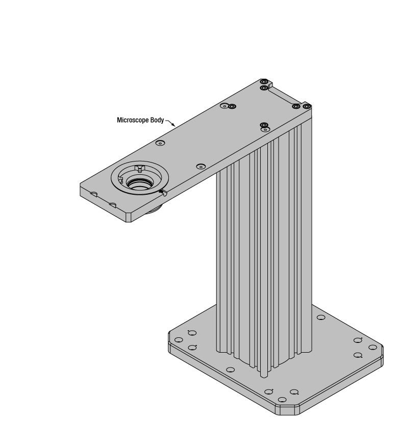 Click to Enlarge
Figure 77C Cerna Microscope Body
Click to Enlarge
Figure 77B Body Details
Microscope Body
The microscope body provides the foundation of any Cerna microscope. The support rail utilizes 95 mm rails machined to a high angular tolerance to ensure an aligned optical path and perpendicularity with the optical table. The support rail height chosen (350 - 600 mm) determines the vertical range available for experiments and microscopy components. The 7.74" throat depth, or distance from the optical path to the support rail, provides a large working space for experiments. Components attach to the body by way of either a linear dovetail on the support rail, or a circular dovetail on the epi-illumination arm (on certain models). Please see the Microscope Dovetails tab or here for further details.
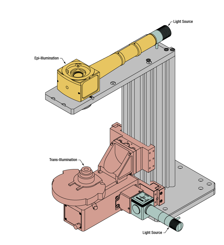 Click to Enlarge
Figure 77D Illumination with a Cerna microscope can come from above (yellow) or below (orange). Illumination sources (green) attach to either.
Illumination
Using the Cerna microscope body, a sample can be illuminated in two directions: from above (epi-illumination, see yellow components in Figure 77D) or from below (trans-illumination, see orange components in Figure 77D).
Epi-illumination illuminates on the same side of the sample as the viewing apparatus; therefore, the light from the illumination source (green) and the light from the sample plane share a portion of the optical path. It is used in fluorescence, confocal, and reflected light microscopy. Epi-illumination modules, which direct and condition light along the optical path, are attached to the epi-illumination arm of the microscope body via a circular D1N dovetail (see the Microscope Dovetails tab or here for details). Multiple epi-illumination modules are available, as well as breadboard tops, which have regularly spaced tapped holes for custom designs.
Trans-illumination illuminates from the opposite side of the sample as the viewing apparatus. Example imaging modalities include brightfield, differential interference contrast (DIC), Dodt gradient contrast, oblique, and darkfield microscopy. Trans-illumination modules, which condition light (on certain models) and direct it along the optical path, are attached to the support rail of the microscope body via a linear dovetail (see Microscope Dovetails tab or here). Please note that certain imaging modalities will require additional optics to alter the properties of the beam; these optics may be easily incorporated in the optical path via lens tubes and cage systems. In addition, Thorlabs offers condensers, which reshape input collimated light to help create optimal Köhler illumination. These attach to a mounting arm, which holds the condenser at the throat depth, or the distance from the optical path to the support rail. The arm attaches to a focusing module, used for aligning the condenser with respect to the sample and trans-illumination module.
 |
 |
 |
 |
 |
 |
 |
 |
| Epi-Illumination Modules | Breadboards & Body Attachments |
Brightfield | DIC | Dodt | Condensers | Condenser Mounting | Light Sources |
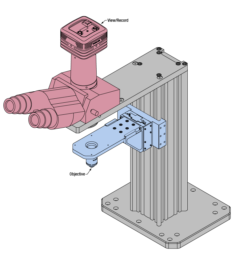 Click to Enlarge
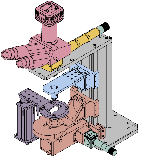
Figure 77E Light from the sample plane is collected through an objective (blue) and viewed using trinocs or other optical ports (pink).
Sample Viewing/Recording
Once illuminated, examining a sample with a microscope requires both focusing on the sample plane (see blue components in Figure 77E) and visualizing the resulting image (see pink components).
A microscope objective collects and magnifies light from the sample plane for imaging. On the Cerna microscope, the objective is threaded onto a nosepiece, which holds the objective at the throat depth, or the distance from the optical path to the support rail of the microscope body. This nosepiece is secured to a motorized focusing module, used for focusing the objective as well as for moving it out of the way for sample handling. To ensure a light-tight path from the objective, the microscope body comes with a bellows (not pictured).
Various modules are available for sample viewing and data collection. Trinoculars have three points of vision to view the sample directly as well as with a camera. Double camera ports redirect or split the optical path among two viewing channels. Camera tubes increase or decrease the image magnification. For data collection, Thorlabs offers both cameras and photomultiplier tubes (PMTs), the latter being necessary to detect fluorescence signals for confocal microscopy. Breadboard tops provide functionality for custom-designed data collection setups. Modules are attached to the microscope body via a circular dovetail (see the Microscope Dovetails tab or here for details).


 Click to Enlarge
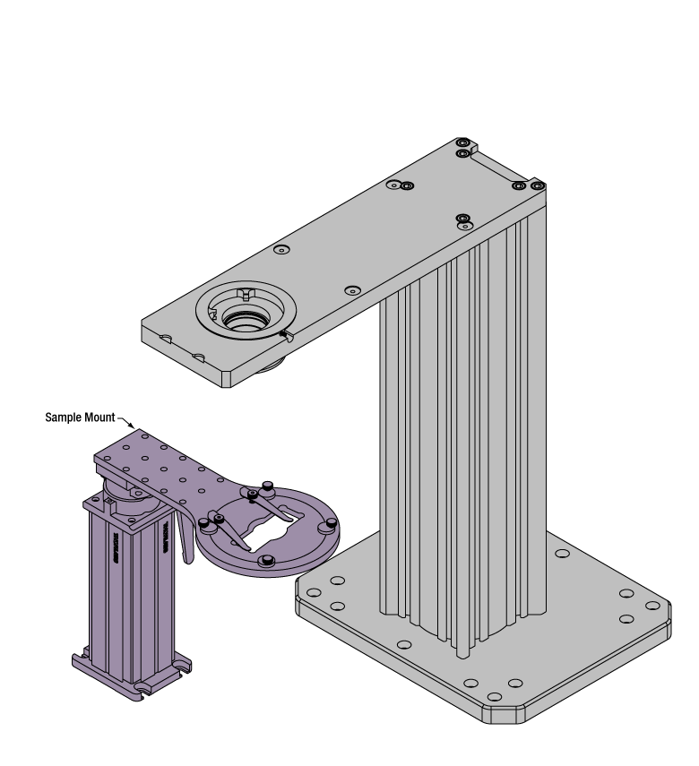
Figure 77F The rigid stand (purple) pictured is one of various sample mounting options available.
Sample/Experiment Mounting
Various sample and equipment mounting options are available to take advantage of the large working space of this microscope system. Large samples and ancillary equipment can be mounted via mounting platforms, which fit around the microscope body and utilize a breadboard design with regularly spaced tapped through holes. Small samples can be mounted on rigid stands (for example, see the purple component in Figure 77F), which have holders for different methods of sample preparation and data collection, such as slides, well plates, and petri dishes. For more traditional sample mounting, slides can also be mounted directly onto the microscope body via a manual XY stage. The rigid stands can translate by way of motorized stages (sold separately), while the mounting platforms contain built-in mechanics for motorized or manual translation. Rigid stands can also be mounted on top of the mounting platforms for independent and synchronized movement of multiple instruments, if you are interested in performing experiments simultaneously during microscopy.
 |
 |
 |
 |
 |
| Translating Platforms | Rigid Stands | Translation Stages for Rigid Stands | Motorized XY Stages | Manual XY Stage |
For sample viewing, Thorlabs offers trinoculars, double camera ports, and camera tubes. Light from the sample plane can be collected via cameras, photomultiplier tubes (PMTs), or custom setups using breadboard tops. Click here for additional information about viewing samples with a Cerna microscope.
| Product Families & Web Presentations | |||
 |
|
 |
 |
| Sample Viewing | Breadboards & Body Attachments |
Cameras | PMTs |
Microscope objectives are held in the optical path of the microscope via a nosepiece. Click here for additional information about viewing a sample with a Cerna microscope.
| Product Families & Web Presentations | ||||
 |
 |
 |
 |
 |
| Objectives | Objective Thread Adapters | Parfocal Length Extender | Piezo Objective Scanner | Objective Mounting |
Large and small experiment mounting options are available to take advantage of the large working space of this microscope. Click here for additional information about mounting a sample for microscopy.
| Product Families & Web Presentations | ||||
|
|
|
|
 |
| Translating Platforms | Rigid Stands | Translation Stages for Rigid Stands | Motorized XY Stages | Manual XY Stage |
Thorlabs offers various light sources for epi- and trans-illumination. Please see the full web presentation of each to determine its functionality within the Cerna microscopy platform.
| Product Families & Web Presentations | ||||
 |
 |
 |
 |
|
| Trans-Illumination Kits | Solis™ High-Power LEDs | Mounted LEDs | X-Cite® Lamps | Other Light Sources |
Epi-illumination illuminates the sample on the same side as the viewing apparatus. Example imaging modalities include fluorescence, confocal, and reflected light microscopy. Click here for additional information on epi-illumination with Cerna.
| Product Families & Web Presentations | ||
|
|
|
| Epi-Illumination | Body Attachments | Light Sources |
Trans-illumination illuminates from the opposite side of the sample as the viewing apparatus. Example imaging modalities include brightfield, differential interference contrast (DIC), Dodt gradient contrast, oblique, and darkfield microscopy. Click here for additional information on trans-illumination with Cerna.
| Product Families & Web Presentations | ||||||
|
|
|
|
 |
|
|
| Brightfield | DIC | Dodt | Condensers | Condenser Mounting | Illumination Kits | Other Light Sources |
The microscope body provides the foundation of any Cerna microscope. The 7.74" throat depth provides a large working space for experiments. Click here for additional information about the Cerna microscope body.
| Product Families & Web Presentations | |
 |
 |
| Microscope Bodies | Microscope Translator |

 Zoom
Zoom

Click for Details
Figure G1.2 Drawing of LAURE1 and LAURE2 Trinoculars
- 10X Eyepieces to Observe FOV with Naked Eye
- Upright-Image Trinoculars
- Available With or Without IR Filters for Eye Protection
- Top-Located Port for Camera Attachment Using Camera Tube
- Adjustable Interpupil Distance
- Male D1N Dovetail on Bottom
These trinoculars are ideal for viewing a sample with the naked eye using the included 10X eyepieces or with a camera connected to the top-located camera port via a camera tube (camera and camera tube sold separately). A lever located on the side of the housing directs the incoming light to either the eyepieces or the camera.
Each camera port has either a D2N or D5N female dovetail connector that accepts a compatible camera tube, which mechanically positions the camera sensor at the image plane and ensures parfocality with the eyepieces. See Table G2.2 for compatible camera tubes. A 2 mm hex key (not included) is used to lock the camera tube in place.
A bottom-located D1N male dovetail connector is provided to attach the trinoculars to other modules such as Cerna microscope bodies, epi-illuminator modules, or double camera ports (available below). For customers interested in constructing a custom system, adapters (available below) that attach directly to the D1N or D2N dovetails on these trinoculars provide compatibility with Thorlabs' 30 mm Cage Systems and SM-Threaded Lens Tubes.
Upright-Image Trinoculars
These LAUREx trinoculars produce an upright image of a sample. The LAURE1 includes a filter before the eyepieces that blocks NIR light. This filter will not block NIR light that is sent to the camera port and it cannot be removed. The LAURE2 does not ship with a blocking filter, but accepts the TF1 NIR blocking filter, available below, with the use of an SM30RR retaining ring (not included).
The drawings for the LAURE1 and LAURE2 trinoculars are shown in Figure G1.2. The LAUREx trinoculars have an internal TTL200 tube lens. This tube lens has a focal length of 200 mm; see Figure G1.2 for the location of the image plane.
These trinoculars incorporate several additional features. A red vibration damping knob on the side of the housing allows the detent mechanism on the carriage slider to be disengaged, which is useful for electrophysiology applications that require minimal vibration when switching between the eyepiece and camera port. They also include a carriage position indicator switch via a 2.5 mm phono jack, allowing users to connect a laser interlock; it is designed to break the circuit in a laser interlock when the carriage is in the eyepiece output position. For custom-built optical detection systems, these trinoculars have 4-40 taps on the top D2N dovetail connector for compatibility with 30 mm cage systems and 4-40 taps on the bottom D1N dovetail for compatibility with 60 mm cage systems.
System Magnification
The total system magnification will be the multiplicative product of the objective magnification and the eyepieces or camera tube magnification, depending on which is being used. To achieve an objective's stated magnification, the objective must have been designed for systems using a 200 mm tube lens. Please note that the eyepieces and camera will see a different FOV due to a difference in magnification in each path. Please see the Magnification & FOV tab for more information on objective's magnification dependance on the system's tube lens and how paths with differing magnifications will see a different FOV.

 Zoom
Zoom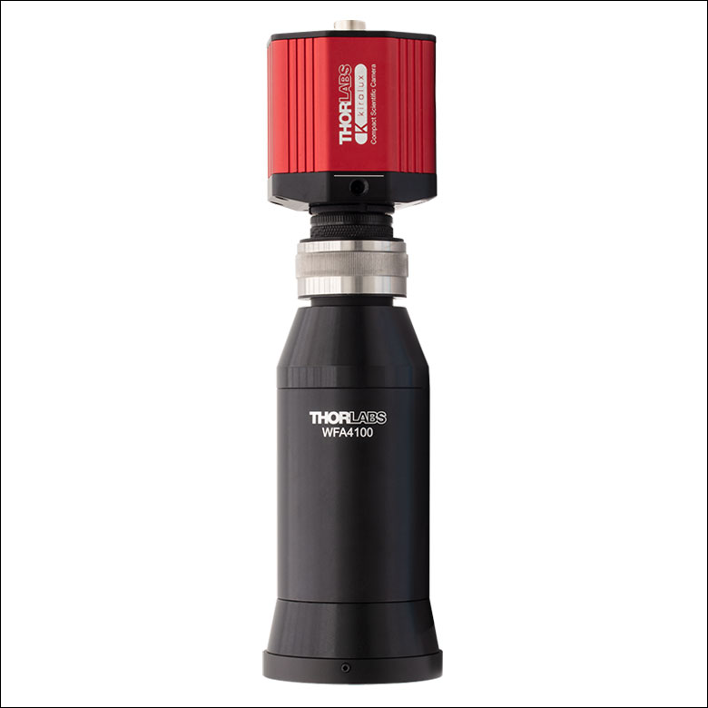
Click to Enlarge
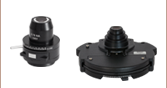
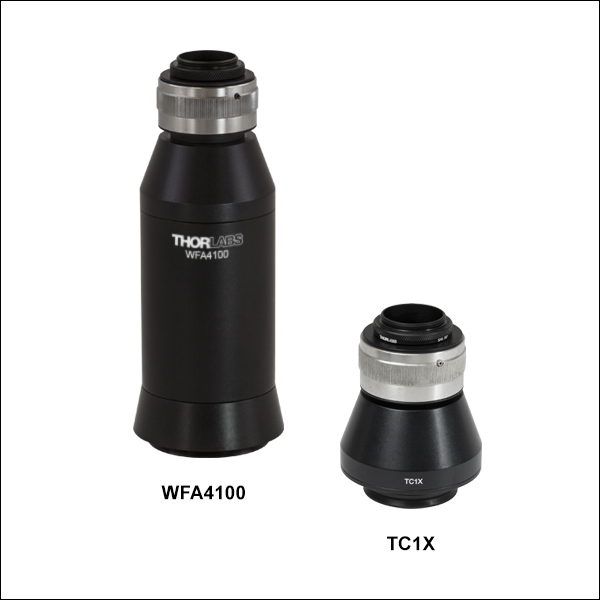
Figure G2.1 Fine Focus Adjuster (Item # SM1ZM) on Camera Tube (Available on Item #'s TC1X, WFA4100, WFA4101, and WFA4102)
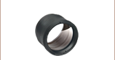
- Positions Camera Sensor at Image Plane with 1X, 0.75X, or 0.5X Magnification
- Versions with Tube Lens Form an Image on a Camera Sensor
- Versions without Tube Lens Provide Optical Distance When Using
Trinoculars or Double Camera Ports - C-Mount (1.00"-32) Threads for Camera Attachment
These camera tubes provide the mechanical spacing necessary to align a camera sensor to the imaging plane in a
The WFA4100, WFA4101, and WFA4102 all include either a 200 mm, 150 mm, or 100 mm focal length tube lens, respectively, which allows them to be used in place of
In contrast, the other camera tubes available here do not have built-in tube lenses. They act as a spacer with or without magnification that positions the camera's sensor at the imaging plane when used with the compatible trinocular or double camera port. The lack of a tube lens and the bottom-located male D2N, D2NB, or D5N male dovetail make them compatible with the rear port of the CSD1002 double camera port (available below) or trinoculars (sold above). Additionally, the D2N dovetail on the TC1X allows it to be used with the LCPN6 Camera Tube Adapter (available below) for the construction of custom assemblies. To compensate for small mechanical tolerances or alignment issues, three 5/64" (2 mm) hex setscrews on the side of the housing can be used to adjust the camera position.
Complete compatibility details can be found in Table G2.2. For more information on the dovetails used, please refer to the Microscope Dovetails tab.
Please note that an adjustable C-mount to SM2 camera tube can be constructed using an SM1A9 Adapter, SM1ZM Zoom Housing, SM1L03 Lens Tube, SM1A2 Adapter, and a Ø2" Stackable Lens Tube, which is used as a spacer to compensate for the working distance of the tube lens. For more details on assembling this camera tube, please see the full presentation for our infinity-corrected tube lenses.
| Table G2.2 Specifications and Compatibility | |||||||
|---|---|---|---|---|---|---|---|
| Item # | Magnificationa,b | Dovetail | Included Tube Lens | Included Camera Focus Adjuster | Compatibility with Trinoculars | Compatibility with Double Camera Ports | Camera Threading |
| WFA4100 | 1X | Male D1N | Yes; f = 200 mm |
Yes (SM1ZM) |
Noc | CSD1001 and CSD1002 Front Port |
C-Mount (1.00"-32) |
| WFA4101 | 0.75X | Yes; f = 150 mm (AC508-150-A) |
|||||
| WFA4102 | 0.5X | Yes; f = 100 mm (AC300-100-A) |
|||||
| WFA4112 | 1X | Male D2NB | No | No | No | CSD1002 Rear Port | |
| TC1X | 1X | Male D2N | No | Yes (SM1ZM) | LAURE1 and LAURE2 | No | |

 Zoom
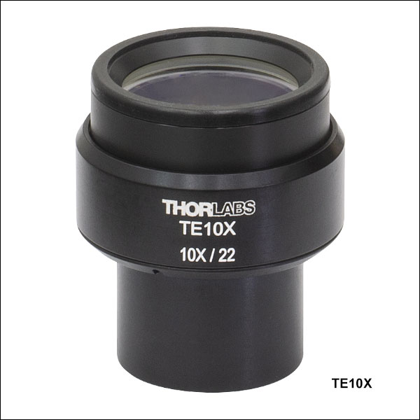
Zoom| Item # | TE10X |
|---|---|
| Microscope Connection | Ø1.18" Eyepiece Tube |
| Magnification | 10X |
| Field Number | 22 |
| Length | 2.05" (52.1 mm) |
- Replacement Eyepiece for Cerna Trinoculars (Sold Above)
- 10X Magnification
- Field Number: 22 mm
The TE10X eyepiece is identical to the ones included in the LAURE1 and LAURE2 Cerna trinoculars. It offers 10X magnification and has a field number of 22. The eyepiece features an adjustable focus that allows users to rotate the housing while not rotating the optics inside. It can be used with reticles and attached to trinoculars by sliding the narrower, Ø1.18" end of the eyepiece into the eyepiece slot on the trinoculars. Three notches on the housing secure the eyepiece in place once installed.

 Zoom
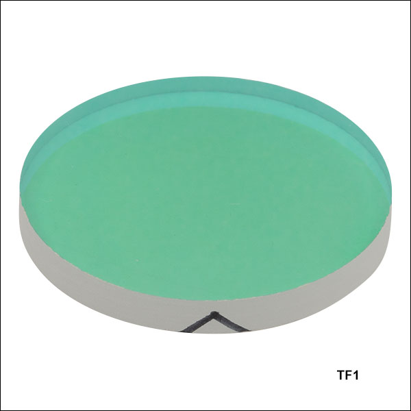
Zoom- IR Filter for Cerna Trinoculars (Sold Above)
- ODavg > 6 in Rejection Region
- Tavg > 90% in Transmission Region
- 30 mm Outer Diameter
The TF1 IR blocking filter is identical to the one included in the LAURE1 Cerna trinoculars. It can be installed before the eyepieces in the LAURE2 trinoculars (sold above), which do not include a blocking filter, using an SM30RR retaining ring (not included); only one filter is needed for both eyepieces. The filter transmits light from 375 - 650 nm and blocks light from 700 - 1400 nm. It features a durable immersed dielectric coating on a Borofloat® substrate.
Note: Borofloat® is a registered trademark by a company of the Schott group.

Click to Enlarge
Click for Raw Data
Figure G4.1 The TF1 filter provides >90% average transmission from 375 to 650 nm, denoted by the blue shaded region.
Click to Enlarge
Click for Raw Data
Figure G4.2 The TF1 filter has an average optical density of >6 from 700 to 1400 nm, denoted by the blue shaded region.
| Item # | TF1 |
|---|---|
| Transmission Region | 375 - 650 nm Tavg> 90% |
| Rejection Region | 700 - 1400 nm ODavg > 6 |
| Construction | Immersed Dielectric |
| Surface Quality | 80-50 Scratch-Dig |
| Substrate Material | Borofloat® |
| Diameter | 30.0 mm (1.18") |
| Diameter Tolerance | ±0.1 mm |
| Clear Aperture | Ø27 mm |
| Thickness | 3.3 mm (0.13") |

 Zoom
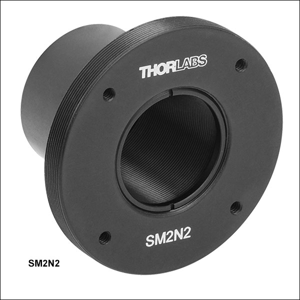
Zoom| Item # | SM2N2 |
|---|---|
| Microscope Connection | Ø1.18" Eyepiece Tube (Alignment Slot, 5 Places) |
| SM Threading |
Internal SM1 (1.035"-40) External SM2 (2.035"-40) |
| Cage Compatibility | 30 mm Cage System (4-40 Tap, One Side, 4 Places) |
| Clear Aperture | Ø0.90" (22.9 mm) |
| Adapter Profile (Click for Drawing) |
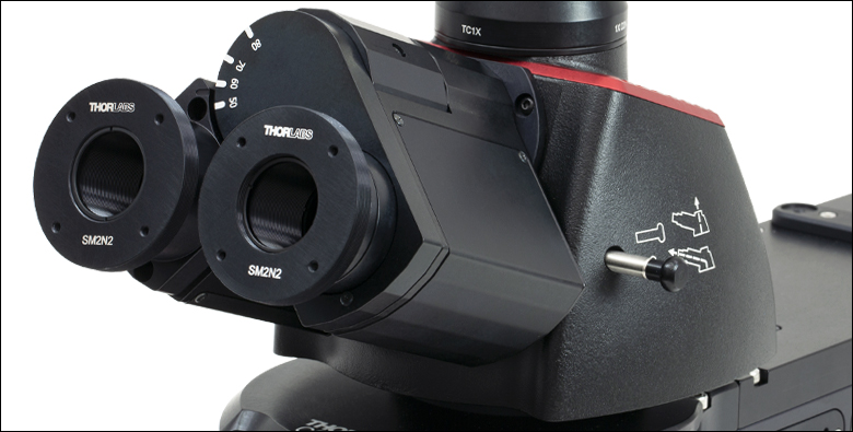
Click to Enlarge
Figure 635A Two SM2N2 adapters attached to the trinocular eyepieces.
- Replace Trinocular Eyepiece for DIY Construction
- Compatible with SM1, SM2, and 30 mm Cage Construction Systems
The SM2N2 Eyepiece Adapter allows custom-built optical detection systems to attach to either eyepiece on the trinoculars of a Cerna Microscope. This adapter replaces the lens element on the eyepiece that sets the image plane at the the back of the eyes (see Figure 635A). Five alignment slots ensure the adapter fits snugly inside the eyepiece without rotation; because of the drop-in nature of this adapter, take care the attached system does not overbalance the 40 g eyepiece adapter when it is inside the trinoculars.
This adapter features internal SM1 (1.035"-40) threading for Ø1" lens tubes; two SM1RR retaining rings are included to secure an optic inside the adapter. The adapter also has external SM2 (2.035"-40) threading for Ø2" lens tubes. The face with the item # engraving has 4-40 tapped holes for 30 mm cage systems.

 Zoom
Zoom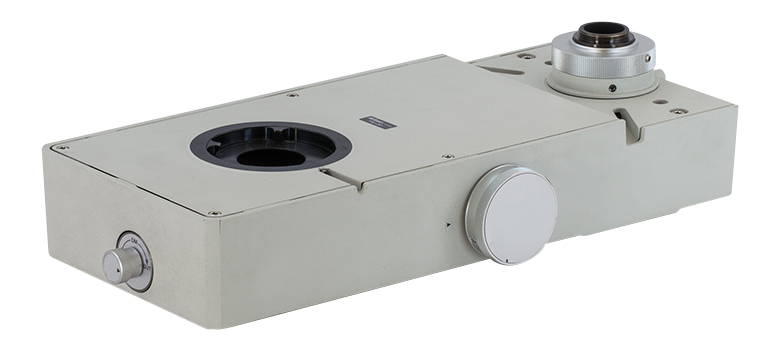
Click to Enlarge
Figure G6.2 Knob on the Front of the CSD1001 Controls Dichroic Mirror to Redirect Light
Click to Enlarge
Figure G6.1 Slider on the Side of the CSD1002 Directs Light to One Camera or the Other
Click to Enlarge
Figure G6.4 CSD1001 Operation Diagram
Click to Enlarge
Figure G6.3 CSD1002 Operation Diagram
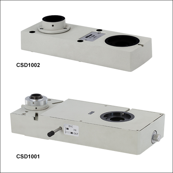
- Allows Two Cameras to be Simultaneously Attached to the Microscope
- CSD1002 Double Camera Port:
- Fixed Magnification
- All Light can Be Sent to the Front or Rear Port
- CSD1001 Double Camera Port:
- Variable Magnification Using a Side-Located Knob
- Light Can be Sent to Front Port or Split with Visible to Front and NIR to Rear
These Double Camera Ports let you simultaneously attach two cameras to a microscope system. The use of two separate cameras, which independently detect the signals from the sample, adds a significant amount of experimental flexibility.
The CSD1002 Double Camera Port provides fixed magnification for the front and rear cameras. As shown in Figure G6.3, this camera port contains an internal silver mirror that can be moved into the optical path to reflect all incoming light to the rear port.
In contrast, the CSD1001 Double Camera Port offers fixed magnification for the front camera and variable magnification of 0.35X, 2X, or 4X for the rear camera. The magnification is set by rotating a knob on the right side of the housing. As shown in Figure G6.4, it also contains an internal dichroic mirror that can be moved into the optic path to transmit visible light to the front port and reflect NIR light to the rear port. A graph showing the transmission and reflectance information can be found in Table G6.6. The rear port also has a built-in NIR DIC analyzer that can be selectively added into the beam path using a side-located lever.
Click to Enlarge
Figure G6.5 LAURE1 Trinoculars Attached to the Front Port of the CSD1001 Double Camera Port
Camera Mounting
The front port of each double camera port contains a female D1N dovetail for mounting widefield assemblies used to view the FOV. As shown in Figures G6.3 and G6.4, there is no internal tube lens prior to the first port of either system. Therefore, any component mounted to this port requires a tube lens to resolve the image from the objective. To remain parfocal with the rear port, the focal length of the tube lens should be 200 mm. Solutions from Thorlabs' DIY Cerna components include any of the camera tubes with a built-in tube lens or our trinoculars (available above). For more information on how the tube lens focal length affects the system magnification, see the Magnification & FOV tab for details.
In contrast to the front port, an internal tube lens is provided before the rear port of each double camera port. The rear port of the CSD1002 has a D2NB dovetail to attach the WFA4112 1X camera tube (available above). This camera tube is designed to mechanically align a mounted camera with the image plane provided by the internal tube lens and contains no internal optics. The rear port for the CSD1001 contains an externally threaded C-Mount (1.00"-32) for direct attachment of a scientific camera that will be parfocal with a camera mounted to the front port (assuming a 200 mm tube lens was used).
| Table G6.6 Specifications | |||
|---|---|---|---|
| Item # | CSD1002 | CSD1001 | |
| Top Connection Interface | Front Port | Female D1N | Female D1N |
| Rear Port | Female D2NBa | Externally Threaded C-Mount (1.00"-32)b | |
| Bottom Connection Interface | Male D1N | Male D1N | |
| Location of Internal Tube Lens | Before Rear Porta | Before Rear Portb | |
| Reflector for Rear Port | Silver Mirrorc | Dichroic Mirror |
|
| Mechanical Drawing (Click for Details) |
 |
 |
|

 Zoom
Zoom
Click for Details
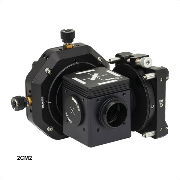
Figure G7.2 Mechanical Diagram of the 2CM2 Double Camera Port
Click for Details
Figure G7.1 Mechanical Diagram of the 2CM1 Double Camera Port
| Table G7.3 Compatible Filters | |||
|---|---|---|---|
| Type | Dimensions | Thickness | |
| Excitation | Ø25 mm | 5 mm | |
| Emission | Ø25 mm | 3.5 mm | |
| Dichroic | Min | 25.0 mm x 35.6 mm | 1.0 mm |
| Max | 25.2 mm x 36.0 mm | 2.0 mm | |
Click to Enlarge
Figure G7.4 Live two-channel composite image generated using 2CM1 Mount, previous-generation scientific CCD cameras, and ThorCam software. The image shows Fluorescence (Pink) and DIC (Grayscale) images of a mouse kidney.
- Microscope Adapters Allow Two Scientific Cameras to Image a Single Optical Input Simultaneously
- Optics Not Included:
- Accepts 25 mm x 36 mm Dichroic Filters or Beamsplitters
- Accepts Standard Ø25 mm or Ø1" Filters on Outputs
- Fine Pitch Rotation and XY Adjustment for Image Co-Registration
- Coarse Focus Adjustment for Parfocalization of Cameras
- Mechanically Adapt to Most Cerna, Olympus, and Nikon Upright Microscopes Using Thorlabs' Standard SM1 Interface (Microscope Camera Port Adapters Sold Separately)
Thorlabs' two-camera mounts are designed to attach two Thorlabs scientific cameras to a standard microscope, allowing simultaneous imaging of a single optical output. A rotation mount allows for 360° of rotational adjustment (±8° fine adjustment) for the reflected camera while a translation mount gives 4 mm linear XY adjustment of the transmitted camera. Both camera mounts have coarse focus adjustment by manually translating the cameras, allowing for parfocalization of both images. The 2CM1 and 2CM2 mounts have up to 15 mm and 11 mm of adjustment, respectively, using the cage rods, although this adjustment range may be limited by the geometry of the camera's front face.
Each mount includes a DFM1 fluorescence filter cube, which is designed to hold a fluorescence filter set (dichroic mirror, excitation filter, and emission filter) as well as plate beamsplitters or other similarly sized optics. See Table G7.3 for compatible optic sizes. The filter cube has an insert to hold filter set components with a kinematic design for easy swapping between mounted filter sets without requiring realignment. A DFM1T1 filter cube insert can also be used for mounting additional filter sets. Please note that these mounts do not include tube lenses.
These camera ports are ideal for use with Thorlabs' scientific cameras and ThorCam software. The 2CM1 mount is designed for cameras with 60 mm cage system taps on the front, such as our cooled sCMOS and CMOS cameras, while the 2CM2 mount is identical except for the inclusion of two LCP4S cage size adapters for compatibility with 30 mm cage system taps, such as those found on our compact scientific cameras with sCMOS and CMOS sensors. The ThorCam user interface, provided for free with our scientific cameras, includes a plug-in to allow for multiple live camera images to be overlaid into a real-time 2-channel composite, eliminating the need for frequent updates of a static overlay image. This live imaging method is ideal for applications such as calcium ratio imaging and electrophysiology.
To see example applications where these camera ports are used and how various filters and dichroics are used, please see the full presentation. For double camera ports with an internal tube lens please see the CSD1001 and CSD1002 above.
Microscope Compatibility
The input port of each camera port adapter has external SM1 (1.035"-40) threading and places Thorlabs scientific cameras' sensors at a distance of 4.05" to 4.17" (102.9 mm to 106.0 mm) from the base of the mount (see Figures G7.1 and G7.2), which may be outside the parfocal distance of some microscopes. See the compatibility information below for details.
Thorlabs' Cerna Microscope Systems
These camera ports can be mounted directly onto our previous-generation inverted-image trinoculars using the SM1A58 adapter (available below). When used with the trinoculars, each mounted camera will be parfocal with the eyepieces. Alternatively, a custom camera tube assembly can also be made to support the two-camera mount. This can be done using the WFA4111 adapter and lens tube or cage system assemblies. When used with upright-image trinocs the camera sensors will not be parfocal with the eyepieces.
Other Commercial Microscopes
Thorlabs offers a line of microscope camera port adapters that will allow these two-camera mounts to be installed on many commercial microscopes. When used with inverted microscopes from Nikon and Olympus the camera sensor will be outside the parfocal distance of the microscope and therefore should only be used if parfocality with the eyepieces is not needed. These mounts will be parfocal with upright microscopes from Nikon and Olympus. For Olympus BX or IX microscopes, Thorlabs offers the SM1A51 camera port adapter with SM1 threading. For upright Nikon Eclipse microscopes, the two-camera mount can be attached to the trinocular's camera port using our SM1A58 camera port adapter.

 Zoom
Zoom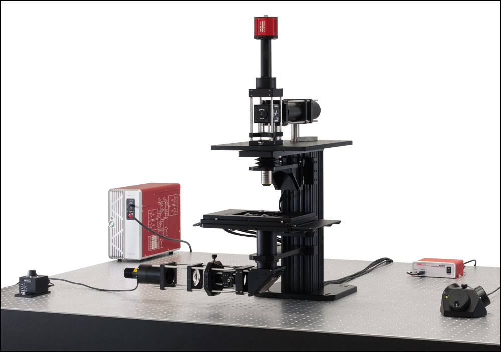
Click for Details
Figure 497B CSA3000 Used to Mount a Custom Epi-Illuminator and Widefield Viewing Apparatus with a sCMOS Camera
Click for Details
Figure 497A CSA3010 Used to Mount a Custom Epi-Illuminator and Widefield Viewing Apparatus with a sCMOS Camera
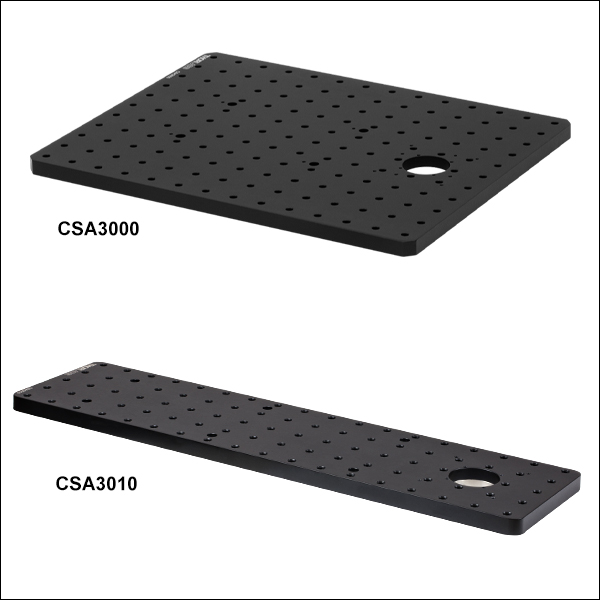
- Male D1N Dovetail on Bottom for Attachment to DIY Cerna Microscope Bodies
- Available in Two Sizes in Imperial and Metric Versions:
- Imperial: 14.00" x 11.00" or 18.00" x 4.60"
- Metric: 350.0 mm x 275.0 mm or 450.0 mm x 116.8 mm
- 1/4"-20 or M6 x 1.0 Mounting Holes
Click to Enlarge
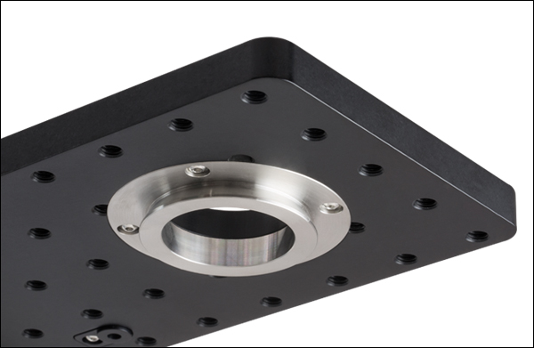
Figure 497C Each breadboard has a male D1N dovetail on the bottom.
These black-anodized aluminum breadboard tops support user-designed widefield viewing apparatuses, epi-illumination pathways, and laser scanning pathways on top of upright Cerna microscopes. Each contains a Ø1.5" (Ø38.1 mm) through hole that is centered on a male D1N dovetail. This dovetail allows the breadboard to be connected directly to the epi-illumination arm of the microscope body, and it can also be used to stack the breadboard on top of an epi-illumination module. Additional details on the dovetail are available in the Microscope Dovetails tab.
The breadboards are available in two sizes. The larger version [Item # CSA3000(/M)] provides additional work surface, but protrudes past the sides of the epi-illumination arm, which may restrict approach angles around the objective for micromanipulators. The smaller version [Item # CSA3010(/M)] does not restrict approach angles and also has eight 4-40 taps around the Ø1.5" through hole for 30 mm and 60 mm cage systems.
In configurations where the breadboard is mounted directly on top of the epi-illumination arm, four M4 counterbores can be used to provide additional mounting stability.
| Item # | CSA3000 | CSA3000/M | CSA3010 | CSA3010/M |
|---|---|---|---|---|
| Dimensions (L x W) | 14.00" x 11.00" | 350.0 mm x 275.0 mm | 18.00" x 4.60" | 450.0 mm x 116.8 mm |
| Breadboard Thickness | 1/2" | 12.7 mm | 1/2" | 12.7 mm |
| Hole Size and Spacing | 1/4"-20 Tapped Holes on 1" Centers |
M6 x 1.0 Tapped Holes on 25 mm Centers |
1/4"-20 Tapped Holes on 1" Centers |
M6 x 1.0 Tapped Holes on 25 mm Centers |
| Number of Tapped Holes |
153 | 153 | 87 | 89 |
| Cage System Compatibility | Four 4-40 Taps for 30 mm Cage Systems Four 4-40 Taps for 60 mm Cage Systems |
|||
| Click for Mechanical Drawing | ||||
| Dovetail | Male D1N | |||
| Material | Matte Black Anodized Aluminum | |||

 Zoom
Zoom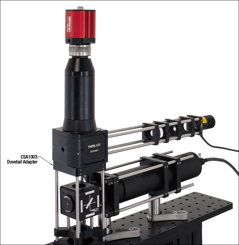
Click for Details
Figure G9.2 In this setup, the CSA1003 D1N Adapter is connecting lens tube and cage system components to a WFA2002 Epi-Illuminator Module.
Click to Enlarge
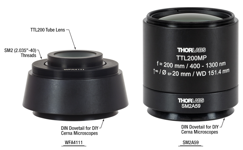
Figure G9.1 The WFA4111 and SM2A59 adapters allow our infinity-corrected tube lenses to be easily integrated with Cerna microscopes and SM2-threaded components.
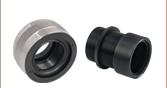
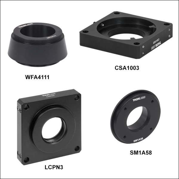
- Extend Versatility of Our Lens Tube and Cage Construction Systems to DIY Cerna Systems
- Compatible with DIY Cerna Modules that Have D1N, D2N, or D2NB Dovetails
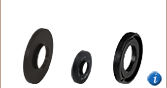
These dovetail adapters integrate Thorlabs' Cerna microscopy platform with our SM1 (1.035"-40) lens tube, SM30 (M30.5 x 0.5) lens tube, SM2 (2.035"-40) lens tube, 30 mm cage, and 60 mm cage construction systems. They are ideal for creating custom widefield viewing, epi-illumination, and trans-illumination apparatuses. Additionally, the WFA4111 and SM2A59 adapters feature internal M38 x 0.5 and SM2 threads, respectively, that can directly accept one of our infinity-corrected tube lenses. We also offer the LCPN3 trinocular port adapter, designed to allow Olympus trinoculars that have a male D5Y dovetail to be used with DIY Cerna systems.
See Table G9.3 for adapter features and Figures G9.1 and G9.2 for application ideas. Please note the dovetail designations are specific to Thorlabs products; see the Microscope Dovetails tab for details.
| Table G9.3 Specifications | |||||
|---|---|---|---|---|---|
| Item # | Dovetaila | Threading | Cage Compatibility | Clear Aperture | Adapter Profile (Click for Drawing) |
| LCPN2 | Male D1N | Internal SM30b | 30 mm Cage System (4-40 Tapc, 4 Places) 60 mm Cage System (Ø6 mm Bore, 4 Places) |
Ø1.10" (27.9 mm) | |
| LCPN3 | Male D1N Female D5Y |
Internal SM30b | 60 mm Cage System (Ø6 mm Bore, 4 Places) |
Ø1.10" (27.9 mm) | |
| WFA4111 | Male D1N | Internal M38 x 0.5d External SM2 |
Nonee | Ø1.47" (37.0 mm) | |
| SM2A59 | Male D1N | Internal SM2f | Nonee | Ø1.69" (43.0 mm) | |
| LCPN4 | Male D1N | Internal SM2g | 60 mm Cage System (Ø6 mm Bore, 4 Places) |
Ø1.74" (44.3 mm) | |
| CSA1003 | Female D1N | None | 60 mm Cage System (Ø6 mm Bore, 4 Places) |
Ø1.50" (38.1 mm) | |
| SM1A58 | Male D2N Male D2NB |
Internal SM1f External SM2 |
30 mm Cage System (4-40 Tap, 4 Places) |
Ø1.008" (25.6 mm) | |
| LCPN6 | Female D2N | Internal SM1f | 30 mm Cage System (4-40 Tapc, 4 Places) 60 mm Cage System (Ø6 mm Bore, 4 Places) |
Ø1.01" (25.6 mm) | |
| LCPY3 | Female D5Y | None | 30 mm Cage System (4-40 Tapc, 4 Places) 60 mm Cage System (Ø6 mm Bore, 4 Places) |
Ø1.26" (32.0 mm) | |