 Products Home / Imaging Components / DIY Cerna Components: Imaging for Home Builders / Laser Scanning for DIY Cerna® Systems
Laser Scanning for DIY Cerna® Systems
- Build or Modify a Laser Scanning System with Various Optical and Mechanical Components
- Support for Photostimulation, Confocal, and Multiphoton Imaging
TTL200MP
Laser Scanning
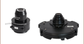
Tube Lens
CSE2000
Epi-Illuminator
Module with Turret
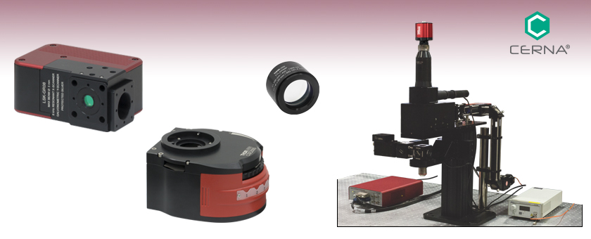
DIY Laser Scanning Cerna® Microscope System
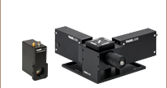
LSK-GR08
Galvo-Resonant Scan Head


Please Wait

Click for Details
DIY Cerna Laser Scanning System using LSKGG4 Galvo-Galvo Scanner, OPX2400 Breadboard Top with Two-Position Slider, SL50-CLS2 Scan Lens, and WFA2001 Epi-Illuminator Module.
Features
- Galvo-Galvo and Galvo-Resonant Scan Head Options
- Telecentric Scan and Tube Lenses with AR Coatings for Single-, Two-, and Three-Photon Excitation
- Breadboard Tops With or Without Two-Position Slider for Combining or Switching Between Optical Paths
- Epi-Illuminator Module with Turret for Six Filter Sets and 60 mm Cage Compatibility
- Dovetail Adapters for Epi-Illumination Arm of Cerna® Microscope Body
- Compatible with Thorlabs' Laser Sources, Detectors, Dichroics, Objectives, and Pinholes
The items on this webpage are used to construct DIY Cerna systems that are capable of laser scanning microscopy. Other components will be needed to complete a DIY Cerna scanning system, such as laser sources, detectors, dichroics, objectives, and pinholes. For more information on these components and to view a complete overview of our Cerna Microscopy Platform, please see the full web presentation.
Thorlabs provides laser scanning kits for either high-speed XY scanning or custom scanning shapes. The LSKGG4(/M) Galvo-Galvo Scanner uses two galvo scan mirrors to trace a scan geometry supplied by the user, while the LSK-GR08(/M) and LSK-GR12(/M) Galvo-Resonant Scanners use one galvo scan mirror and one resonant scan mirror to scan at high speeds. Every laser scanning kit utilizes two mirrors with a protected silver coating for high reflectance of visible and NIR laser beams. Each scan head includes mounting features for Thorlabs' SM1 (1.035"-40) and SM05 (0.535"-40) threading, and 30 mm cage construction systems. See the Galvo vs Resonant tab for a features comparison between galvo and resonant scanning.
In addition, Thorlabs has engineered telecentric scan and tube lenses that are fully corrected and AR coated for multiple broadband wavelength ranges spanning the visible and NIR. Identical to the optics used in our Bergamo® II multiphoton microscopes, four-channel Cerna-based confocal systems, and Veneto® inverted microscopy platform, these scan and tube lenses support field numbers up to 20 (i.e., up to a Ø20 mm entrance pupil at the objective), making them able to capture large-area images. Our scan lenses have external SM30 (M30 x 0.5) threads for mounting, while our tube lenses have internal and/or external SM2 (2.035"-40) threads.
To couple the laser path into the objective, we offer breadboard tops with 1/4"-20 (M6 x 1.0) tapped holes, with or without a two-position optic slider; the large aperture of the optic slider is ideal for applications requiring large area scanning. For pairing this imaging modality with epi-fluorescence or photoactivation, the CSE2000 epi-illuminator module holds six filter sets and has four 4-40 taps for our 60 mm cage system. For custom builds, we offer D1N dovetail adapters that provide connections from the top of the epi-illumination arm to our SM30, 30 mm cage, and 60 mm cage construction systems. We also have available the LCPN3 trinocular port adapter, designed to allow Olympus trinoculars that have a male D5Y dovetail to be used with DIY Cerna systems.
Laser-Scanning Beam Diagram Using Cerna Components
Click on Each Component to See Its Web Presentation
| Scanning Methodologies | |
|---|---|
| Galvanometer-Based Scanning | Advantage: Flexible Scan Positioning Disadvantage: Slow |
| Resonant Scanning |
Advantage: Scan Speed Disadvantage: Unable to Adjust Center of Resonant Scan Area; Nonlinear Dwell Time |
Galvo Versus Resonant Scanning
Galvo and resonant scanning provide orthogonal advantages due to their respective scanning mechanisms. As a result, it is important to choose the scanning methodology that is ideal for the intended application. For instance, galvo-galvo scanning is optimal for user-defined scanning paths and shapes, while galvo-resonant scanning is optimal for high-speed scans.
Galvanometer-based scanning uses a galvanometric mirror steered by an assembly system of a servo-controlled motor and a positioning actuator. The angle of the mirror is tightly controlled in the system and can be controlled via an external signal for accurate positioning and scanning, providing the flexibility for user-defined scan lines and areas. Due to inertia, the velocity of a galvo scanner has a low upper limit.
While resonant scanning also utilizes a galvanometric mirror, the scanning method differs significantly. In a manner similar to that of a tuning fork, the mirror assembly is driven at its resonant frequency in order to reach over 10X faster scan speeds than that of galvo scanning. The speed of the resonant galvanometric mirror varies sinusoidally with the scanning angle in order to maintain smooth motion over the course of the scan, which results in longer dwell times at the edges of the FOV and shorter dwell times at the center of the scan. The combination of this effect and the fixed center position and frequency of the resonant scanner results in an inability to scan complex patterns or adjust the scanning speed. The only user-variable parameter of the resonant scan mirror is the maximum scan angle.
| Thorlabs Dovetail Referencea | |||
|---|---|---|---|
| Type | Shape | Outer Dimension | Angle |
| 95 mm | Linear | 95 mm | 45° |
| D1N | Circular | Ø2.018" | 60° |
| D2Nb | Circular | Ø1.50" | 90° |
| D2NBb | Circular | Ø1.50" | 90° |
| D3N | Circular | Ø45 mm | 70° |
| D5N | Circular | Ø1.58" | 90° |
| D6N | Circular | Ø1.90" | 90° |
| D7N | Circular | Ø2.05" | 90° |
| D1T | Circular | Ø1.50" | 60° |
| D3T | Circular | Ø1.65" | 90° |
| D1Y | Circular | Ø107 mm | 60° |
| D2Y | Circular | Ø2.32" | 50° |
| D3Y | Circular | Ø1.75" | 90° |
| D4Y | Circular | Ø56 mm | 60° |
| D5Y | Circular | Ø46 mm | 60° |
| D6Y | Circular | Ø41.9 mm | 45° |
| D1Z | Circular | Ø54 mm | 60° |
| D2Z | Circular | Ø57 mm | 60° |
| D3Z | Circular | Ø54 mm | 45° |
Click to Enlarge
This photo shows the male D1N dovetail on the trinoculars next to the female D1N dovetail on the epi-illumination arm.

Click to Enlarge
This photo shows the male 95 mm dovetail on the microscope body and the female 95 mm dovetail on the CSA1002 Fixed Arm.
Introduction to Microscope Dovetails
Dovetails are used for mechanical mating and optical port alignment of microscope components. Components are connected by inserting one dovetail into another, then tightening one or more locking setscrews on the female dovetail. Dovetails come in two shapes: linear and circular. Linear dovetails allow the mating components to slide before being locked down, providing flexible positioning options while limiting unneeded degrees of freedom. Circular dovetails align optical ports on different components, maintaining a single optical axis with minimal user intervention.
Thorlabs manufactures many components which use dovetails to mate with our own components or those of other manufacturers. To make it easier to identify dovetail compatibility, we have developed a set of dovetail designations. The naming convention of these designations is used only by Thorlabs and not other microscope manufacturers. The table to the right lists all the dovetails Thorlabs makes, along with their key dimensions.
In the case of Thorlabs’ Cerna® microscopes, different dovetail types are used on different sections of the microscope to ensure that only compatible components can be mated. For example, our WFA2002 Epi-Illuminator Module has a male D1N dovetail that mates with the female D1N dovetail on the microscope body's epi-illumination arm, while the CSS2001 XY Microscopy Stage has a female D1Y dovetail that mates with the male D1Y dovetail on the CSA1051 Mounting Arm.
To learn which dovetail type(s) are on a particular component, consult its mechanical drawing, available by clicking on the red Docs icon ( ) below. For adapters with a female dovetail, the drawing also indicates the size of the hex key needed for the locking setscrew(s). It is important to note that mechanical compatibility does not ensure optical compatibility. Information on optical compatibility is available from Thorlabs' web presentations.
For customers interested in machining their own dovetails, the table to the right gives the outer diameter and angle (as defined by the drawings below) of each Thorlabs dovetail designation. However, the dovetail's height must be determined by the user, and for circular dovetails, the user must also determine the inner diameter and bore diameter. These quantities can vary for dovetails of the same type. One can use the intended mating part to verify compatibility.
In order to reduce wear and simplify connections, dovetails are often machined with chamfers, recesses, and other mechanical features. Some examples of these variations are shown by the drawings below.

Click to Enlarge
Two examples of how circular male dovetails can be manufactured.
Click to Enlarge
Two examples of how circular female dovetails can be manufactured.
Standard Mechanical Interfaces on DIY Cerna® Components
The table below gives the dovetail, optical component threads, and cage system interfaces that are present on each DIY Cerna component. If a DIY Cerna component does not have one of the standard interfaces in the table, it is not listed here. Please note that mechanical compatibility does not ensure optical compatibility. Information on optical compatibility is available from Thorlabs' web presentations.
| Item # | Microscope Dovetails | Optical Component Threadsa | Cage Systemsb | ||||||||||
|---|---|---|---|---|---|---|---|---|---|---|---|---|---|
| 95 mm | D1N | D2N | D2NB | D3N | D5N | D1T | D3T | D1Y | D5Y | Internal | External | ||
| 2CM1 | - | - | - | - | - | - | - | - | - | - | SM1c (1.035"-40) and SM2d (2.035"-40) | SM1c (1.035"-40) | 60 mmd |
| 2CM2 | - | - | - | - | - | - | - | - | - | - | SM1c (1.035"-40) and SM2d (2.035"-40) | SM1c (1.035"-40) | 30 mmc |
| BSA2000e | - | - | - | - | Female | - | - | - | - | - | - | - | - |
| CEA1350 | Male | Female | - | - | - | - | - | - | - | - | - | - | 60 mmd |
| CEA1400 | Male | Female | - | - | - | - | - | - | - | - | - | - | 60 mmd |
| CEA1500 | Male | Female | - | - | - | - | - | - | - | - | - | - | 60 mmd |
| CEA1600 | Male | Female | - | - | - | - | - | - | - | - | - | - | 60 mmd |
| CFB1500 | Male | - | - | - | - | - | - | - | - | - | - | - | - |
| CSA1000 | Female | - | - | - | - | - | - | - | - | - | - | - | - |
| CSA1001 | Female | - | - | - | - | - | - | - | - | - | SM1c (1.035"-40) | - | 30 mmc |
| CSA1002 | Female | - | - | - | - | - | - | - | - | - | SM2d (2.035"-40) | - | 60 mmd |
| CSA1003 | - | Female | - | - | - | - | - | - | - | - | - | - | 60 mmd |
| CSA1051 | Female | - | - | - | - | - | - | - | Male | - | - | - | - |
| CSA1200e,f | - | - | - | - | - | - | - | - | - | - | - | - | 60 mmd |
| CSA1400e | - | - | - | - | - | - | Female | - | - | - | - | - | 60 mmd |
| CSA1500e,g | - | - | - | - | - | - | - | - | - | - | - | - | - |
| CSA2000e | - | - | - | - | Female | - | - | - | - | - | SM2d (2.035"-40) | - | 60 mmd |
| CSA2001 | - | - | - | - | Female | - | - | - | - | - | - | SM2d (2.035"-40) | - |
| CSA2100e | - | - | - | - | - | - | - | - | - | - | SM2d (2.035"-40) | - | 60 mmd |
| CSA3000(/M) | - | Male | - | - | - | - | - | - | - | - | - | - | - |
| CSA3010(/M) | - | Male | - | - | - | - | - | - | - | - | - | - | 30 mmc and 60 mmd |
| Item # | 95 mm | D1N | D2N | D2NB | D3N | D5N | D1T | D3T | D1Y | D5Y | Internal | External | Cage Systems |
| CSC1001 | - | - | - | - | Male | - | - | - | - | - | - | - | - |
| CSC1002 | - | - | - | - | Male | - | - | - | - | - | - | - | - |
| CSC2001 | - | - | - | - | Male | - | - | - | - | - | - | - | - |
| CSD1001 | - | Male & Female | - | Female | - | - | - | - | - | - | - | - | - |
| CSD1002 | - | Male & Female | - | - | - | - | - | - | - | - | - | C-Mounth | - |
| CSE2000 | - | Male & Female | - | - | - | - | - | - | - | - | - | - | 60 mmd |
| CSE2100 | - | Male & Female | - | - | - | - | - | Female | - | - | SM1c (1.035"-40) | - | 30 mmc and 60 mmd |
| CSE2200 | - | Male & Female | - | - | - | - | - | Female | - | - | SM1c (1.035"-40) | - | 30 mmc and 60 mmd |
| CSN100e | - | - | - | - | - | - | - | - | - | - | M32 x 0.75 | - | 60 mmd |
| CSN110 | - | - | - | - | - | - | Male | - | - | - | M32 x 0.75 | - | 30 mmc and 60 mmd |
| CSNK10 | - | - | - | - | - | - | - | - | - | - | M32 x 0.75 | - | 60 mmd |
| CSNK100e | - | - | - | - | - | - | - | - | - | - | M32 x 0.75 | - | 60 mmd |
| CSN200 | - | - | - | - | - | - | Male | - | - | - | M32 x 0.75 | - | - |
| CSN210 | - | - | - | - | - | - | Male | - | - | - | M32 x 0.75 | - | - |
| CSN1201f | - | - | - | - | - | - | - | - | - | - | M32 x 0.75 | - | - |
| CSN1202f | - | - | - | - | - | - | - | - | - | - | M25 x 0.75 | - | - |
| CSS2001 | - | - | - | - | - | - | - | - | Female | - | - | - | - |
| LAURE1 | - | Male | Female | - | - | - | - | - | - | - | - | - | - |
| LAURE2 | - | Male | Female | - | - | - | - | - | - | - | - | - | - |
| LCPN1 | - | - | - | - | Male | - | - | - | - | - | SM30 (M30.5 x 0.5) | - | 30 mmc and 60 mmd |
| LCPN2 | - | Male | - | - | - | - | - | - | - | - | SM30 (M30.5 x 0.5) | - | 30 mmc and 60 mmd |
| Item # | 95 mm | D1N | D2N | D2NB | D3N | D5N | D1T | D3T | D1Y | D5Y | Internal | External | Cage Systems |
| LCPN3 | - | Male | - | - | - | - | - | - | - | Female | SM30 (M30.5 x 0.5) | - | 60 mmd |
| LCPN4 | - | Male | - | - | - | - | - | - | - | - | SM2d (2.035"-40) | - | 60 mmd |
| LCPN5 | - | - | - | - | Male | - | - | - | - | - | SM2d (2.035"-40) | - | 60 mmd |
| LCPN6 | - | - | Female | - | - | - | - | - | - | - | SM1c (1.035"-40) | - | 30 mmc and 60 mmd |
| LCPY2 | - | - | - | - | - | - | - | - | - | Male | SM30 (M30.5 x 0.5) | - | 30 mmc and 60 mmd |
| LCPY3 | - | - | - | - | - | - | - | - | - | Female | - | - | 30 mmc and 60 mmd |
| OPX2400(/M) | - | Male & Female | - | - | - | - | - | - | - | - | SM2d (2.035"-40) | - | 60 mmd |
| SM1A70 | - | - | - | - | - | - | - | - | - | - | SM30 (M30.5 x 0.5) | SM1c (1.035"-40) | - |
| SM1A58 | - | - | Male | Male | - | - | - | - | - | - | SM1c (1.035"-40) | SM2d (2.035"-40) | 30 mmc |
| SM2A56 | - | - | - | - | - | - | - | Male | - | - | - | SM2d (2.035"-40) | - |
| SM2A59 | - | Male | - | - | - | - | - | - | - | - | SM2d (2.035"-40) | - | - |
| TC1X | - | - | Male | - | - | - | - | - | - | - | - | - | - |
| WFA0150 | Female | - | - | - | - | - | - | - | - | - | - | - | - |
| WFA1000 | - | - | - | - | - | - | - | - | - | - | - | - | 30 mmc |
| WFA1010 | - | - | - | - | - | - | - | - | - | - | SM1c (1.035"-40) | - | 30 mmc |
| WFA1020 | - | - | - | - | - | - | - | - | - | - | SM1c (1.035"-40) | - | 30 mmc |
| WFA1051 | - | - | - | - | - | - | - | - | - | - | SM1c (1.035"-40) | - | 30 mmc |
| WFA1100 | - | - | - | - | - | - | - | - | - | - | - | - | 30 mmc |
| WFA2001 | - | Male & Female | - | - | - | - | - | - | - | - | SM1c (1.035"-40) | SM1c (1.035"-40) | - |
| WFA2002 | - | Male & Female | - | - | - | - | - | - | - | - | SM1c (1.035"-40) | - | 30 mmc |
| Item # | 95 mm | D1N | D2N | D2NB | D3N | D5N | D1T | D3T | D1Y | D5Y | Internal | External | Cage Systems |
| WFA4100 | - | Male | - | - | - | - | - | - | - | - | SM1c (1.035"-40) | C-Mounth | - |
| WFA4101 | - | Male | - | - | - | - | - | - | - | - | SM1c (1.035"-40) | C-Mounth | - |
| WFA4102 | - | Male | - | - | - | - | - | - | - | - | SM1c (1.035"-40) | C-Mounth | - |
| WFA4111 | - | Male | - | - | - | - | - | - | - | - | - | SM2d (2.035"-40) | - |
| WFA4112 | - | - | - | Male | - | - | - | - | - | - | - | C-Mounth | - |
| Female | - | - | - | - | - | - | - | - | - | - | - | - | |
| Female | - | - | - | - | - | - | - | - | - | - | - | - | |
| Female | - | - | - | - | - | - | - | - | - | - | - | - | |
| Female | - | - | - | - | - | - | - | - | - | - | - | - | |
| XT95P12(/M) | Female | - | - | - | - | - | - | - | - | - | - | - | - |
| ZFM1020 | Female | - | - | - | - | - | - | - | - | - | - | - | - |
| ZFM1030 | Female | - | - | - | - | - | - | - | - | - | - | - | - |
| ZFM2020 | Female | - | - | - | - | - | - | - | - | - | - | - | - |
| ZFM2030 | Female | - | - | - | - | - | - | - | - | - | - | - | - |
Cerna® microscopes support several imaging modalities, including epi-fluorescence, brightfield illumination, differential interference contrast (DIC) imaging, and Dodt gradient contrast imaging. Each of these methods requires different accessories and confers different advantages to the microscopist, as described below.
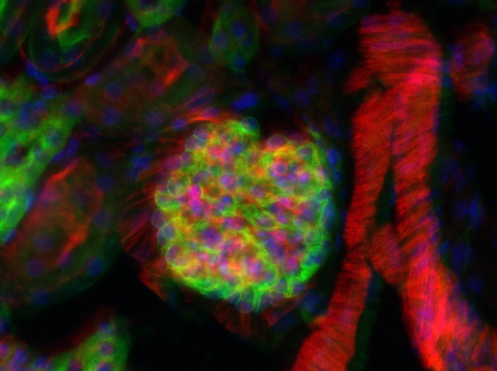
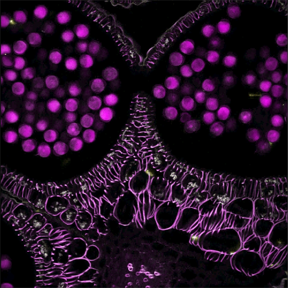
Click to Enlarge
Epi-Fluorescence Image of Mouse Kidney with Multiple Labels
Epi-Fluorescence
Epi-fluorescence makes use of fluorescent labels and intrinsic fluorescence in a specimen to identify sample features. To create an epi-fluorescence image, light that has been passed through an excitation filter is directed through an objective and absorbed by a sample. This excitation causes fluorophores within the sample to emit light of a longer wavelength (i.e., lower energy) than the excitation light. Some of this emitted light is collected by the objective, which helps direct the emission onto a camera for observation. Additional details on this imaging modality are available here.
For performing epi-fluorescence measurements in DIY Cerna systems, we offer a range of widefield viewing and epi-illumination accessories, as well as fluorescence filter sets targeted at common fluorophores.
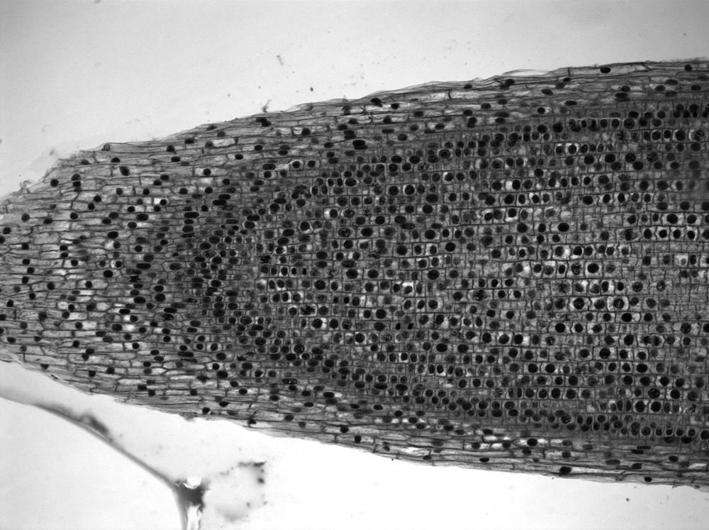
Click for Details
Brightfield Image of Onion Mitosis
Brightfield Illumination
Brightfield illumination is the simplest method of trans-illumination. In this modality, light from an illumination source is collected by a condenser and passed through a sample, which is observed by its effect on the intensity of the transmitted light. Brightfield illumination only requires an illumination source (i.e., an illumination kit) and a condenser to be attached to a DIY Cerna system.
Click to Enlarge
DIC Image of a Buttercup Root
DIC Imaging
In differential interference contrast (DIC) imaging, light transmitted through the sample is manipulated by a number of polarization optics. Light from the illumination source is polarized and then split into two orthogonally polarized beams before it reaches the sample. Small differences in the optical path length experienced by the two beams cause interference when the beams are recombined, providing enhanced contrast for sample features that would be transparent under brightfield illumination. In addition to an illumination source and a condenser, DIC imaging requires several additional optical elements: a DIC polarizer, a condenser prism, an objective prism, and an analyzer.
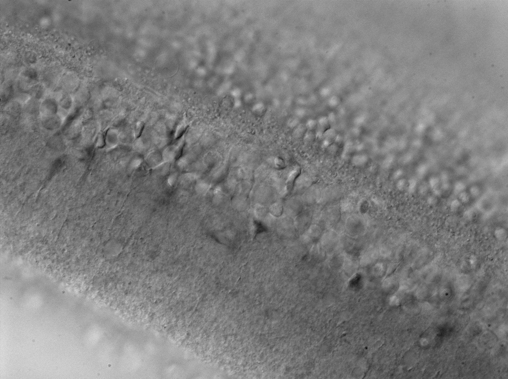
Click to Enlarge
Dodt Contrast Image of a Mouse Retina
Dodt Contrast
Dodt gradient contrast, also known more simply as Dodt contrast, can be understood as an improvement upon oblique illumination. Both methods use a mask to generate an illumination gradient, but in Dodt contrast, the mask occurs much earlier in the optical path. This configuration improves the image contrast to a point where it is comparable to that obtained using DIC.
The Dodt illumination gradient is generated using a specially shaped quarter annulus and diffusers, and reveals thickness changes in a sample over the field of view. Compared to brightfield illumination, Dodt contrast offers improved resolution of sample features, and compared to DIC, it allows thicker samples to be studied. Thorlabs manufactures a pre-configured, pre-aligned illumination module for Dodt contrast that generates the desired gradient; it requires an illumination source and a condenser for operation.
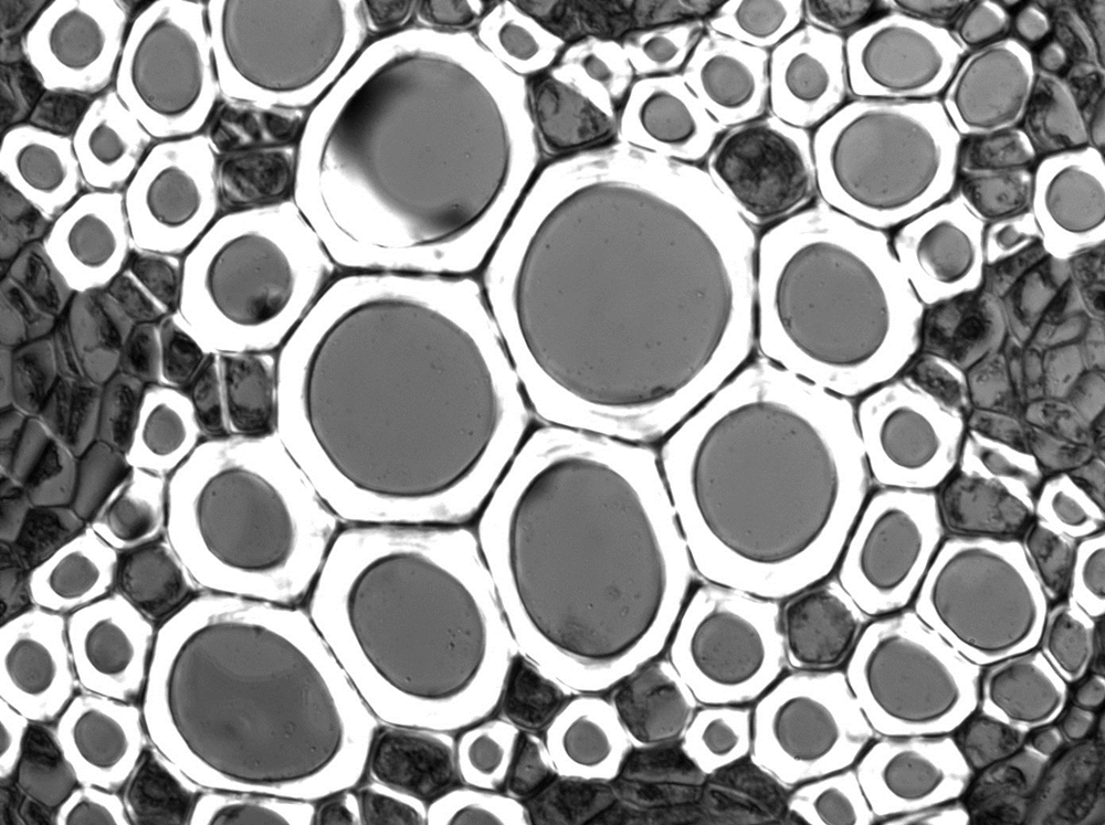
Click to Enlarge
Laser Scanned Image of a Flower Bud
Laser Scanning
Like epi-fluorescence, laser scanning makes use of fluorescent labels and intrinsic fluorescence in a specimen to identify sample features. Unlike epi-fluorescence, laser scanning is able to resolve thin individual planes relatively deep into a thick sample, enabling 3D volumetric images and opening the door to in vivo studies.
Laser scanning techniques (e.g., multiphoton and confocal microscopy) rely upon the coherence of laser beams to provide significantly improved axial resolution. In confocal microscopy, a pinhole eliminates the out-of-focus light that would reduce the axial resolution (as it does in epi-fluorescence), while in multiphoton microscopy, the necessity of two- or three-photon absorption by the fluorophore, a low-probability event, effectively creates optical sections.
Additional details are available at our laser scanning microscopy tutorial.
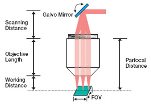
Scan lenses are used in a variety of laser imaging systems, including confocal laser scanning microscopy and multiphoton imaging systems. In these applications, a laser beam incident on the back aperture (entrance pupil) of the lens is scanned through a range of angles. This translates the position of the spot formed in the image plane across the lens' field of view. In the case of non-telecentric lenses, this approach to scanning the focal spot through the image plane would introduce severe aberrations that would significantly degrade the quality of the resulting image. Telecentric scan lenses are designed to create a uniform spot size in the image plane at every scan position, which allows a high-quality image of the sample to be formed.
In general, laser scanning microscopy systems pair a scan lens with a tube lens to create an infinity-corrected optical system. The CLS-SL, SL50-CLS2, SL50-2P2, and SL50-3P scan lenses were optimized for use in Thorlabs' confocal laser scanning and multiphoton microscopy systems. (In most OCT systems, the scan lens is designed to be used without a tube lens.)
Click to Enlarge
The tube and scan lens schematic above shows the lens spacing for the SL50-2P2 scan lens used with a 200 mm focal length telecentric tube lens. Note that for the SL50-CLS2, the entrance pupil at the scan plane is a maximum of Ø4 mm.
Scan Lenses Implemented in General Laser Scanning Microscopy Applications
The image to the right shows the proper spacing of the scan and tube lenses for laser scanning microscopy. The scanning mirror, which is located at the left of the image at the scan plane, directs the laser beam through the scan lens. The angle at which the laser beam is incident on the scan lens determines the position of the focal spot in the intermediate image plane, which is located between the scan lens and the tube lens. The tube lens is positioned so that it collects and collimates the light (the focus is at infinity). The collimated light is collected by the objective, which brings it to a focus on the sample plane. Light scattered or emitted from the sample plane is collected by the objective and directed to a detector. The image below and to the left shows a CLS-SL scan lens paired with a tube lens; clicking on the image shows the correct spacing for using the CLS-SL with the TTL200 series and ITL200 tube lenses.
An attractive feature of this optical system design is the collimated light that is produced as a result of pairing the scan lens with the tube lens. With the light from the tube lens focusing at infinity, it is possible to move the position of the objective with respect to the tube lens without impacting the image quality at the sample plane. This imparts considerable flexibility to the design of the optical system. If no tube lens were used, the scan lens would also function as the objective and the intermediate image plane would become the sample plane. It would not be possible to move the image plane much with respect to the scan lens while maintaining image quality.
The image below and to the right shows the relationship between the scan distance and the objective distance. In a perfect 4f optical system (using the CLS-SL as an example), d1 = 52 mm (minimum scan distance) and d2 = f2. However, in many practical cases the system is slightly deviated from this perfect alignment. For instance, in many commercial microscopes, the objective distance (d2) is not the same as the focal length (f2), so there may be a need to adjust distances. The figure below and to the right shows the scan and objective distance moved by some small distance δ1 and δ2, respectively. The relationship between these values is δd1 = -δd2*(f1/f2)2.
Click for Details
CLS-SL Tube Lens used with the ITL200 tube lens and an objective in a laser scanning system.
When designing an imaging system that uses a scan lens, it is important to accommodate the design wavelength, parfocal distance, scanning distance, entrance pupil, and scan angle specifications in order to maximize the image quality. In general, the larger the input beam diameter, the smaller the focused spot size. However, due to the effects of vignetting and/or increased aberrations, the range of scan angles decreases as the diameter of the beam increases. Beams smaller than the entrance pupil specification will result in spot sizes larger than those specified, and beams with larger diameters will be clipped.
For imaging systems with a single galvo mirror, the center of the scan lens' entrance pupil is coincident with the pivot point of the galvo mirror. When a single galvo mirror is used, the scanning distance is measured from the mounting surface of the lens to the pivot point of the mirror. This is shown in the image at bottom-left.
If the imaging system uses two galvo mirrors (one to scan in the X direction and one to scan in the Y direction), the entrance pupil is located between the two galvo mirrors, as is shown in the image at bottom-right. The scanning distance is then the distance from the shoulder of the lens housing to the pivot point of the mirror closest to the lens (d1) plus the distance from the pivot point of that mirror to the entrance pupil (d2). It is important to minimize the distance between the two galvo mirrors, because when the entrance pupil and beam steering pivot point are not coincident, the quality of the image is degraded. This is principally due to the variation in the optical path length as the beam is scanned over the sample. Below are schematics for an imaging system containing one and two galvo mirrors.
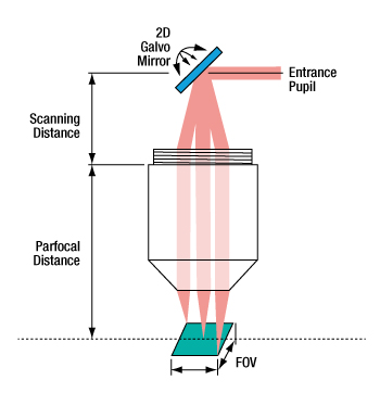
When one galvo mirror is used, the entrance pupil
is located at the pivot point of the mirror.
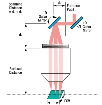
When two galvo mirrors are used, the entrance
pupil is located between the mirrors.
Building a Cerna® Microscope
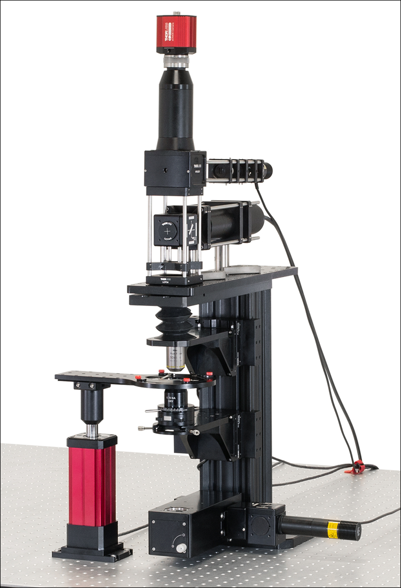
The Cerna microscopy platform's large working volume and system of dovetails make it straightforward to connect and position the components of the microscope. This flexibility enables simple and stable set up of a preconfigured microscope, and provides easy paths for later upgrades and modification. See below for a couple examples of the assembly of some DIY Cerna microscopes.
DIY Cerna Design and Assembly
Walkthrough of a DIY Microscope Configuration
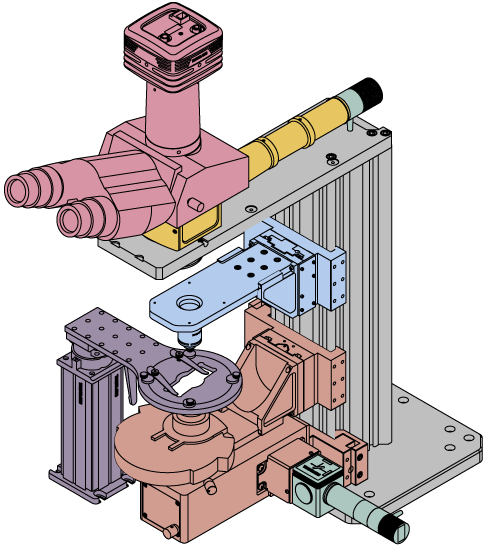
This DIY microscope uses a CSA3000(/M) Breadboard Top, a CSA2001 Dovetail Adapter, our CSA1001 and CSA1002 Fixed Arms, and other body attachments and extensions. These components provide interfaces to our lens tube and cage construction systems, allowing the rig to incorporate two independent trans-illumination modules, a home-built epi-illumination path, and a custom sample viewing optical path.
The simplicity of Thorlabs optomechanical interfaces allows a custom DIY microscope to be quickly assembled and reconfigured for custom imaging applications.
Click on the different parts of the microscope to explore their functions.
Elements of a Microscope
This overview was developed to provide a general understanding of a Cerna® microscope. Click on the different portions of the microscope graphic to the right or use the links below to learn how a Cerna microscope visualizes a sample.
Terminology
Arm: Holds components in the optical path of the microscope.
Bayonet Mount: A form of mechanical attachment with tabs on the male end that fit into L-shaped slots on the female end.
Bellows: A tube with accordion-shaped rubber sides for a flexible, light-tight extension between the microscope body and the objective.
Breadboard: A flat structure with regularly spaced tapped holes for DIY construction.
Dovetail: A form of mechanical attachment for many microscopy components. A linear dovetail allows flexible positioning along one dimension before being locked down, while a circular dovetail secures the component in one position. See the Microscope Dovetails tab or here for details.
Epi-Illumination: Illumination on the same side of the sample as the viewing apparatus. Epi-fluorescence, reflected light, and confocal microscopy are some examples of imaging modalities that utilize epi-illumination.
Filter Cube: A cube that holds filters and other optical elements at the correct orientations for microscopy. For example, filter cubes are essential for fluorescence microscopy and reflected light microscopy.
Köhler Illumination: A method of illumination that utilizes various optical elements to defocus and flatten the intensity of light across the field of view in the sample plane. A condenser and light collimator are necessary for this technique.
Nosepiece: A type of arm used to hold the microscope objective in the optical path of the microscope.
Optical Path: The path light follows through the microscope.
Rail Height: The height of the support rail of the microscope body.
Throat Depth: The distance from the vertical portion of the optical path to the edge of the support rail of the microscope body. The size of the throat depth, along with the working height, determine the working space available for microscopy.
Trans-Illumination: Illumination on the opposite side of the sample as the viewing apparatus. Brightfield, differential interference contrast (DIC), Dodt gradient contrast, and darkfield microscopy are some examples of imaging modalities that utilize trans-illumination.
Working Height: The height of the support rail of the microscope body plus the height of the base. The size of the working height, along with the throat depth, determine the working space available for microscopy.
 Click to Enlarge
Cerna Microscope Body
Click to Enlarge
Body Details
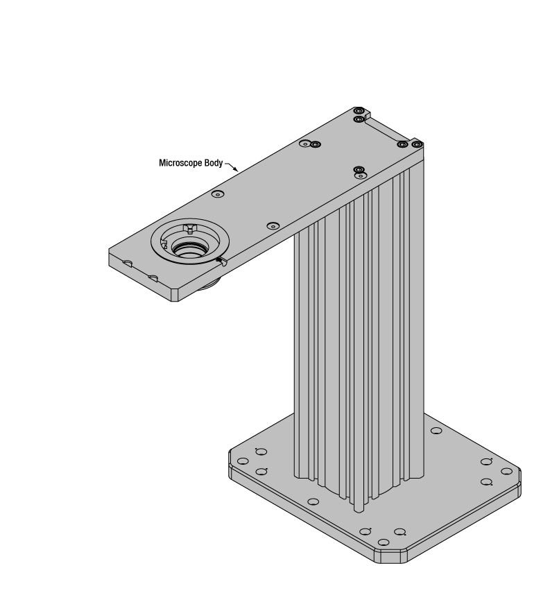
Microscope Body
The microscope body provides the foundation of any Cerna microscope. The support rail utilizes 95 mm rails machined to a high angular tolerance to ensure an aligned optical path and perpendicularity with the optical table. The support rail height chosen (350 - 600 mm) determines the vertical range available for experiments and microscopy components. The 7.74" throat depth, or distance from the optical path to the support rail, provides a large working space for experiments. Components attach to the body by way of either a linear dovetail on the support rail, or a circular dovetail on the epi-illumination arm (on certain models). Please see the Microscope Dovetails tab or here for further details.
 Click to Enlarge
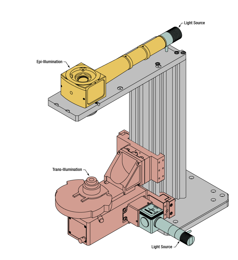
Illumination with a Cerna microscope can come from above (yellow) or below (orange). Illumination sources (green) attach to either.
Illumination
Using the Cerna microscope body, a sample can be illuminated in two directions: from above (epi-illumination, see yellow components to the right) or from below (trans-illumination, see orange components to the right).
Epi-illumination illuminates on the same side of the sample as the viewing apparatus; therefore, the light from the illumination source (green) and the light from the sample plane share a portion of the optical path. It is used in fluorescence, confocal, and reflected light microscopy. Epi-illumination modules, which direct and condition light along the optical path, are attached to the epi-illumination arm of the microscope body via a circular D1N dovetail (see the Microscope Dovetails tab or here for details). Multiple epi-illumination modules are available, as well as breadboard tops, which have regularly spaced tapped holes for custom designs.
Trans-illumination illuminates from the opposite side of the sample as the viewing apparatus. Example imaging modalities include brightfield, differential interference contrast (DIC), Dodt gradient contrast, oblique, and darkfield microscopy. Trans-illumination modules, which condition light (on certain models) and direct it along the optical path, are attached to the support rail of the microscope body via a linear dovetail (see Microscope Dovetails tab or here). Please note that certain imaging modalities will require additional optics to alter the properties of the beam; these optics may be easily incorporated in the optical path via lens tubes and cage systems. In addition, Thorlabs offers condensers, which reshape input collimated light to help create optimal Köhler illumination. These attach to a mounting arm, which holds the condenser at the throat depth, or the distance from the optical path to the support rail. The arm attaches to a focusing module, used for aligning the condenser with respect to the sample and trans-illumination module.
 |
 |
 |
 |
 |
 |
 |
 |
| Epi-Illumination Modules | Breadboards & Body Attachments |
Brightfield | DIC | Dodt | Condensers | Condenser Mounting | Light Sources |
 Click to Enlarge
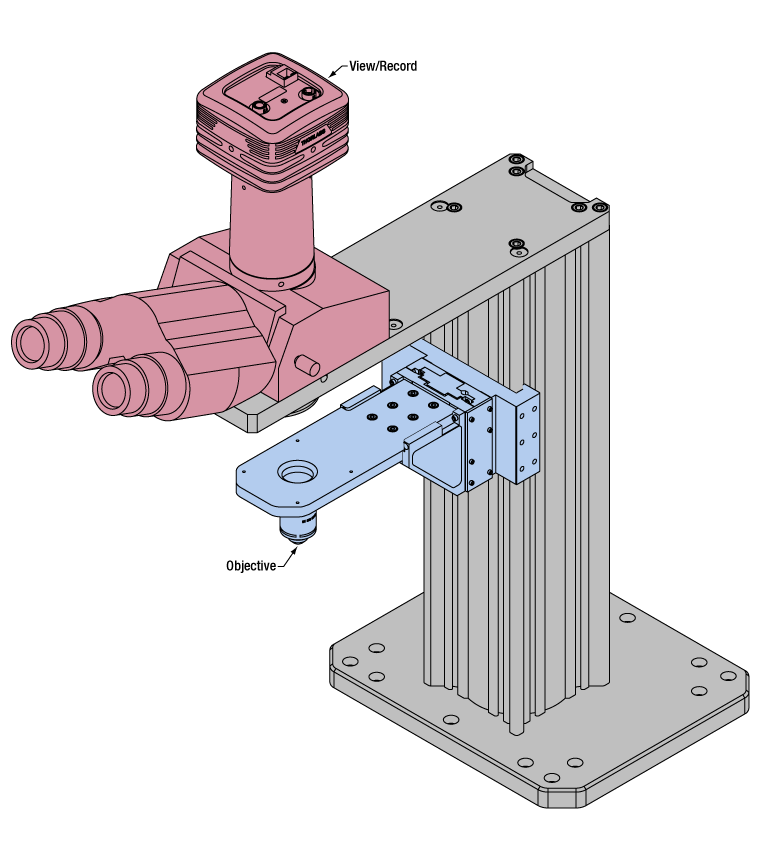
Light from the sample plane is collected through an objective (blue) and viewed using trinocs or other optical ports (pink).
Sample Viewing/Recording
Once illuminated, examining a sample with a microscope requires both focusing on the sample plane (see blue components to the right) and visualizing the resulting image (see pink components).
A microscope objective collects and magnifies light from the sample plane for imaging. On the Cerna microscope, the objective is threaded onto a nosepiece, which holds the objective at the throat depth, or the distance from the optical path to the support rail of the microscope body. This nosepiece is secured to a motorized focusing module, used for focusing the objective as well as for moving it out of the way for sample handling. To ensure a light-tight path from the objective, the microscope body comes with a bellows (not pictured).
Various modules are available for sample viewing and data collection. Trinoculars have three points of vision to view the sample directly as well as with a camera. Double camera ports redirect or split the optical path among two viewing channels. Camera tubes increase or decrease the image magnification. For data collection, Thorlabs offers both cameras and photomultiplier tubes (PMTs), the latter being necessary to detect fluorescence signals for confocal microscopy. Breadboard tops provide functionality for custom-designed data collection setups. Modules are attached to the microscope body via a circular dovetail (see the Microscope Dovetails tab or here for details).


 Click to Enlarge
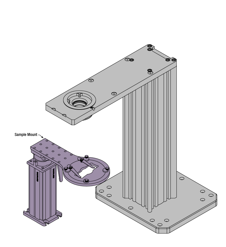
The rigid stand (purple) pictured is one of various sample mounting options available.
Sample/Experiment Mounting
Various sample and equipment mounting options are available to take advantage of the large working space of this microscope system. Large samples and ancillary equipment can be mounted via mounting platforms, which fit around the microscope body and utilize a breadboard design with regularly spaced tapped through holes. Small samples can be mounted on rigid stands (for example, see the purple component to the right), which have holders for different methods of sample preparation and data collection, such as slides, well plates, and petri dishes. For more traditional sample mounting, slides can also be mounted directly onto the microscope body via a manual XY stage. The rigid stands can translate by way of motorized stages (sold separately), while the mounting platforms contain built-in mechanics for motorized or manual translation. Rigid stands can also be mounted on top of the mounting platforms for independent and synchronized movement of multiple instruments, if you are interested in performing experiments simultaneously during microscopy.
 |
 |
 |
 |
 |
| Translating Platforms | Rigid Stands | Translation Stages for Rigid Stands | Motorized XY Stages | Manual XY Stage |
For sample viewing, Thorlabs offers trinoculars, double camera ports, and camera tubes. Light from the sample plane can be collected via cameras, photomultiplier tubes (PMTs), or custom setups using breadboard tops. Click here for additional information about viewing samples with a Cerna microscope.
| Product Families & Web Presentations | |||
 |
|
 |
 |
| Sample Viewing | Breadboards & Body Attachments |
Cameras | PMTs |
Microscope objectives are held in the optical path of the microscope via a nosepiece. Click here for additional information about viewing a sample with a Cerna microscope.
| Product Families & Web Presentations | ||||
 |
 |
 |
 |
 |
| Objectives | Objective Thread Adapters | Parfocal Length Extender | Piezo Objective Scanner | Objective Mounting |
Large and small experiment mounting options are available to take advantage of the large working space of this microscope. Click here for additional information about mounting a sample for microscopy.
| Product Families & Web Presentations | ||||
|
|
|
|
 |
| Translating Platforms | Rigid Stands | Translation Stages for Rigid Stands | Motorized XY Stages | Manual XY Stage |
Thorlabs offers various light sources for epi- and trans-illumination. Please see the full web presentation of each to determine its functionality within the Cerna microscopy platform.
| Product Families & Web Presentations | ||||
 |
 |
 |
 |
|
| Trans-Illumination Kits | Solis™ High-Power LEDs | Mounted LEDs | X-Cite® Lamps | Other Light Sources |
Epi-illumination illuminates the sample on the same side as the viewing apparatus. Example imaging modalities include fluorescence, confocal, and reflected light microscopy. Click here for additional information on epi-illumination with Cerna.
| Product Families & Web Presentations | ||
|
|
|
| Epi-Illumination | Body Attachments | Light Sources |
Trans-illumination illuminates from the opposite side of the sample as the viewing apparatus. Example imaging modalities include brightfield, differential interference contrast (DIC), Dodt gradient contrast, oblique, and darkfield microscopy. Click here for additional information on trans-illumination with Cerna.
| Product Families & Web Presentations | ||||||
|
|
|
|
 |
|
|
| Brightfield | DIC | Dodt | Condensers | Condenser Mounting | Illumination Kits | Other Light Sources |
The microscope body provides the foundation of any Cerna microscope. The 7.74" throat depth provides a large working space for experiments. Click here for additional information about the Cerna microscope body.
| Product Families & Web Presentations | |
 |
 |
| Microscope Bodies | Microscope Translator |
| Posted Comments: | |
wenzel.jakob
(posted 2017-11-27 10:28:38.877) The combination of the SL50-CLS2 scan lens and TL200-CLS2 tube lens transmit almost no light at 405 nm. Is it possible to combine TTL200MP or ITL200 tube lenses with a CLS-SL scan lens to scan a 405nm laser using the LSK-GG? tfrisch
(posted 2018-01-19 03:21:45.0) Hello, thank you for contacting Thorlabs. Yes, CLS-SL can be used with ITL200 and LSK-GG. I will reach out to you directly to discuss your application. |

 Zoom
Zoom
Click for Details
Cutaway View of Galvo-Galvo Scan Head
The scan lens being used with the scan head needs to be positioned such that its entrance pupil is at the midpoint of the 4.33 mm green line.
| Key Specificationsa | |
|---|---|
| Scan Range | ±7.5° Mechanical (±15° Optical) |
| Beam Diameter |
4 mm (Max) |
| Linearity | 99.9% |
| Repeatability | 8 µradb |
| Small Angle Step Responsec |
130 μs (Typical) |
| Maximum Step Angled |
0.65° |
| Time Delay Between Input and Output | 90 μs |
| Input Bandwidth | 0 - 500 Hz (Max)e |
- Optical Scan Range of ±15° (±7.5° Mechanical Scan Range) for Beams up to Ø4 mm
- Driven by User-Supplied DC, Sine, or Sawtooth Wave Signal
- BNC Connectors and NI 68-Pin Connector for Position Control and Readout
- Protected Silver Coating for High Reflectance in Visible and NIR
- Scan Head is SM05, SM1, 30 mm Cage, and Post Mountable
Our LSKGG4 Galvo-Galvo Scanner contains two galvo scan mirrors that deflect an incident laser beam in X and Y. Identical to the galvo-galvo scanner used in our Bergamo II multiphoton microscopes, four-channel Cerna-based confocal systems, and Veneto inverted microscopy platform, each mirror has a mechanical scan range of ±7.5°, corresponding to an optical scan range of ±15°. This range is large enough to explore the entire diffraction-limited FN20 field of view of Thorlabs' SL50 scan lenses for laser scanning microscopy.
A National Instruments (NI) 68-pin connector is available to directly control and monitor the scanner via an NI card or breakout box (not included). The beam can also be steered by supplying DC or sine wave drive signals through two BNC connectors. For sine wave signals, a maximum scan rate of 500 Hz is supported. Two additional BNC connectors provide X and Y position feedback signals. This scanner is also compatible with Vidrio's ScanImage software.
Each scan mirror has a protected silver coating that provides high reflectance in the visible and NIR. Click here for a typical reflectance curve at a 45° AOI. Since the coating is metallic, its performance varies minimally over the ±7.5° mechanical scan range of the mirror.
The scan head is connected to the controller using the included DB25 cable. If using the BNC input connectors to drive the galvo mirrors, a drive voltage of ±10 V at an impedance of 200 kΩ will be required for each axis. The BNC output connectors have a voltage range of ±4 V and an impedance of 2 kΩ.
Complete specifications and usage details are available at our full web presentation.
Mounting
The input face of the scan head has internal SM05 (0.535"-40) threads, internal SM1 (1.035"-40) threads, and four Ø6 mm bores spaced for our 30 mm cage system, while the output face has internal SM1 threads and four 4-40 taps for our 30 mm cage system. The scan lens needs to be positioned such that its entrance pupil is at the midpoint between the galvo mirrors; when being used at the input, the distance is 27.255 mm, while at the output, the distance is 29.045 mm. For the CLS-SL Scan Lens, an LCP02 (/M) Cage System Size Adapter can be used to convert the 30 mm cage system to a 60 mm cage system to mount and position this scan lens at the correct distance using a LCP8S Cage Plate. An SM1A70 adapter (sold below) with external SM1 and internal SM30 mounting threads will position our SL50-CLS2, SL50-2P2, or SL50-3P Scan Lens at the correct distance from the scanner output port.
The scan head weighs 0.56 kg, so it may be useful to support it directly using a Ø1/2" post or Ø1" post. Four 1/4"-20 (M6) tapped holes are located on the bottom.

 Zoom
Zoom
Click to Enlarge
Cutaway View of Galvo-Resonant Scan Head
The scan lens being used with the scan head needs to be positioned such that its entrance pupil is at the midpoint of the 7.13 mm green line between the resonant mirror (X) and the galvo mirror (Y).
| Item #a | LSK-GR08 | LSK-GR12 |
|---|---|---|
| Galvo Scan Range | ±7.5° Mechanical (±15° Optical) | |
| Resonant Scan Range | ±5° Mechanical (±10° Optical) |
±2.5° Mechanical (±5° Optical) |
| Beam Diameter |
5 mm (Max) | |
| Resonant Scanner Frequency | 7910 ± 15 Hz | 12000 ± 15 Hz |
| Galvo BNC Input Bandwidth | 0 - 500 Hz (Max)b | |
- 8 kHz or 12 kHz Resonant Scanner Frequency for High-Speed XY Scans
- Control via BNC Connectors, Software, and NI 68-Pin Connector
- Protected Silver Coating for High Reflectance in Visible and NIR
- Scan Head is SM1, 30 mm Cage, and Post Mountable
Our Galvo-Resonant (GR) Scanners are available with 8 kHz or 12 kHz resonant scanner frequency. Each scanner contains one resonant scan mirror and one galvo scan mirror that deflect an incident laser beam in X and Y, respectively. The resonant frequency of the resonant scan mirror enables much higher-speed scans than a galvo-galvo system. The LSK-GR08(/M) 8 kHz and LSK-GR12(/M) 12 kHz GR scanners are used in our Bergamo II multiphoton microscopes, four-channel Cerna-based confocal systems, and Veneto inverted microscopy platform. In our Bergamo system, the 8 kHz GR scanner can achieve 30 fps at 512 x 512 pixels image resolution, while the 12 kHz GR scanner can achieve 45 fps at 512 x 512 pixels image resolution.
The beam can be steered via two BNC connectors for simple uni-directional scans. For fine tuning and bi-directional scanning functionality, we provide a GUI for Windows® to adjust the scan range of the resonant scan mirror and the sync signal offset, as well as a National Instruments (NI) 68-pin connector to directly control and monitor the galvo scan mirror via an NI card or breakout box (not included). See the full web presentation for details. Each scanner is also compatible with Vidrio's ScanImage software.
Each scan mirror has a protected silver coating that provides high reflectance in the visible and NIR. Click here for a typical reflectance curve at a 45° AOI. Since the coating is metallic, the performance varies minimally over the scan range of the mirror. The scan head input port also features an NIR window that, when combined with a scan lens on the output port, greatly reduces the audible noise from the system.
Mounting
The input face of each scan head has four Ø6 mm bores spaced for our 30 mm cage system. By removing the NIR window installed on the input face using a SPW801 spanner wrench, internal SM05 (0.535"-40) and internal
SM1 (1.035"-40) threads become accessible. The output face is equipped with internal SM1 threads and four 4-40 taps for our 30 mm cage system.
The scan lens needs to be positioned such that its entrance pupil is at the midpoint between the galvo and resonant mirrors. The distance from the input face to the midpoint is 28.655 mm, while the distance from the output face to the midpoint is 28.965 mm. An SM1A70 adapter (sold below) with external SM1 and internal SM30 mounting threads will position our SL50-CLS2, SL50-2P2, or SL50-3P Scan Lens at the correct distance from the scanner output port.
The scan head weighs 0.76 kg, so it may be useful to support it directly using a Ø1" post. Four 1/4"-20 (M6) tapped holes are located on the bottom.

 Zoom
Zoom- Telecentric Multiphoton Tube Lenses, and Telecentric Scanning and Tube Lens Pairs
- AR Coated for Single-, Two-, or Three-Photon Excitation
- TTL200MP: 400 - 1300 nm
- TTL200MP2: Broadband Single-Layer MgF2 Coating
- SL50-CLS2: 450 - 1100 nm
- SL50-2P2: 680 - 1300 nm
- SL50-3P: 800 - 1800 nm
- Telecentric Design Provides Constant Spot Sizes Across the Field of View
- Diffraction-Limited Field of View up to FN20 at Objective Plane, Depending Upon Wavelength
- Each Scan and Tube Lens is Individually Corrected for Aberrations
- Optic Designs Based on Our Bergamo II Multiphoton Microscopes, Four-Channel Cerna-Based Confocal Systems, and Veneto Inverted Microscopy Platform
Multiphoton Telecentric Tube Lens
Thorlabs' TTL200MP and TTL200MP2 infinity-corrected telecentric tube lenses are optimized for multiphoton imaging and other laser scanning applications. These tube lenses feature diffraction-limited axial color correction and resolution over the broadband wavelength range of 400 - 2000 nm, and are AR coated. The TTL200MP tube lens provides higher transmission at visible and NIR wavelengths, while the TTL200MP2 tube lens provides higher transmission at longer wavelengths approaching 2000 nm. Their effective focal length of 200 mm is the design focal length used by Thorlabs, Nikon, Leica, and Mitutoyo objectives. Click the Complete Tube Lens Specifications box below for performance data.
Due to the large design wavelength range of these tube lenses, they can be paired with any of the scan lenses featured below.
Telecentric Tube and Scan Lens Pairs
These scan and tube lenses have been optimized for point-by-point (raster) laser scanning within one of three super broadband wavelength ranges: 450 - 1100 nm, 680 - 1300 nm, or 800 - 1800 nm. Optimized for single-, two-, and three-photon excitation, respectively, they support a diverse range of experimental needs, including confocal and multiphoton imaging, as well as photostimulation and uncaging. Depending upon the lens and the wavelengths used, field numbers up to 20 (i.e., an entrance pupil at the objective up to Ø20 mm) are supported, as shown by clicking on the Complete Lens Specifications boxes below. For reference, if a 20X objective is used with a lens pair that supports a field number of 20, the field of view will be Ø1 mm.
Telecentric lens systems produce spot sizes in the sample plane that are nearly constant over the entire field of view, resulting in image resolution that varies minimally over the scanned area of the sample. Additional information on telecentricity is available from our telecentric lenses tutorial. Our scan and tube lenses are each individually corrected for aberrations, so it is also possible to use this tube lens with another aberration-corrected scan lens.
Mounting Ideas
Our scan lenses have external SM30 (M30 x 0.5) mounting threads on the end that should face the galvo scanning system. Please note that the scan lens needs to be positioned such that the scanning distance is at the midpoint between the galvo and resonant mirrors. Because of the 37.8 mm scanning distance, these lenses need to be placed in close proximity to the scanner. An SM1A70 adapter (sold below) with external SM1 and internal SM30 mounting threads will position the scan lens at the correct distance from the scanner output port when used with the scanners sold on this page.
Our tube lenses have external SM2 threads on both sides that can be used to mount the tube lens into a Ø2" lens tube or a 60 mm cage plate. If using the OPX2400(/M) Breadboard Top with Two-Position Slider, the tube lens can also be threaded directly into the optic slider.
These tube lenses are engraved with an infinity symbol (∞) next to an arrow to indicate which side of the lens should face the objective (infinity space).
Complete Tube Lens Specifications
| Item # | TTL200MP | TTL200MP2 |
|---|---|---|
| Design Wavelength Range |
400 - 2000 nm | |
| AR Coating Range | 400 - 1300 nm | Broadband Single-Layer MgF2 Coating |
| Effective Focal Length | 200 mm | |
| Working Distancea | 151.4 mm | |
| Pupil Distanceb | 228 mm (Telecentric) | |
| Track Length | 420 mm (Nominal) | |
| Entrance Pupil Diameter | 20 mm | |
| f/# | 10 | |
| Field Size (Diffraction Limited) | Ø22 mm | |
| Clear Aperture | Ø36.8 mm | |
| Lens Design | Apochromatic | |
| Axial Color | Diffraction Limited | |
| F-Theta Distortion | <0.2% | |
| Threading | External SM2 Threads (Top and Bottom) | |
| Housing Length |
44.1 mm | |
| Performance Data (Click for Graph) | ||
| Transmission |  |
|
| Axial Color |  |
|
| RMS Wavefront Error |  |
|
| MTF |
 |
|
| Data | Excel Spreadsheet | Excel Spreadsheet |
| Zemax Black Box Files | Forward Backward |
Forward Backward |
Click To Enlarge
This schematic shows the TTL200MP Tube Lens in a laser scanning configuration with the working distance and pupil distance called out. The working distance corresponds to the distance from the edge of the housing below the engraving to the intermediate image plane. The pupil distance is defined as the distance between the edge of the tube lens housing above the engraving and the entrance pupil of the objective.
Complete Scan Lens Specifications
The complete specifications available for each scan lens are provided in the table below, and definitions of the various parameters follow the table. Click the blue icons, ![]() , to view the plots. All plots below show theoretical data.
, to view the plots. All plots below show theoretical data.
| Scan Lens Item # | SL50-CLS2 | SL50-2P2 | SL50-3P | ||
|---|---|---|---|---|---|
| Optical Specifications | |||||
| Wavelength Range | 450 - 1100 nm | 680 - 1300 nm | 800 - 1800 nm | ||
| Effective Focal Length (EFL) | 50 mm | ||||
| Entrance Pupil Diametera | 4 mm | 5 mm | |||
| Parfocal Distance | 77.3 mm | ||||
| Lens Working Distance | 26.4 mm | ||||
| Scanning Distanceb | 37.8 ± 4 mm | ||||
| Optical Scan Anglec (Single-Axis Scan) |
Maximum | ±11.5° | |||
| Diffraction Limited | ±7.5° (at 486.1 nm) ±9° (at 587.6 nm) ±11.5° (656.6 - 1100 nm) |
±7.2° (at 680 nm) ±8° (at 800 nm) ±11.5° (1000 - 1300 nm) |
±8.0° (at 800 nm) ±8.5° (at 900 nm) ±11.5° (1000 - 1800 nm) |
||
| Optical Scan Anglec (Two-Axis Scan) |
Maximum | ±8.1° x ±8.1° | ±8.5° x ±8.5° | ||
| Diffraction Limited | ±5.3° x ±5.3° (at 486.1 nm) ±6.3° x ±6.3° (at 587.6 nm) ±8.1° x ±8.1° (656.6 - 1100 nm) |
±5.3° x ±5.3° (at 680 nm) ±6.3° x ±6.3° (at 800 nm) ±8.1° x ±8.1° (1000 - 1300 nm) |
±6.0° x ±6.0° (at 900 nm) ±8.5° x ±8.5° (1000 - 1800 nm) |
||
| Spot Size Plotsa |
Single-Axis Scan: |
Single-Axis Scan: |
Single-Axis Scan:  |
||
| Field of Viewd |
Maximum | 14.1 x 14.1 mm2, FN20 (Two-Axis Scan) | |||
| Diffraction Limited | 9.2 x 9.2 mm2, FN13 (at 486.1 nm) 11.1 x 11.1 mm2, FN15.7 (at 587.6 nm) 14.1 x 14.1 mm2, FN20 (656.5 - 1100 nm) |
8.9 x 8.9 mm2, FN12.6 (at 680 nm) 9.9 x 9.9 mm2, FN14 (at 800 nm) 14.1 x 14.1 mm2, FN20 (1000 - 1300 nm) |
10.5 x 10.5 mm2, FN14.8 (at 900 nm) 14.1 x 14.1 mm2, FN20 (1000 - 1800 nm) |
||
| F-Theta Distortione | <0.2% | ||||
| Field Curvaturee | <500 µm | <700 µm | |||
| Axial Color | <80 µm for 450 - 1100 nm <25 µm for 680 - 1100 nm Plot: |
<25 µm for 680 - 1100 nm Plot: |
<250 µm (800 to 1800 nm) Plot:  |
||
| f/# | 12.5 | 12.5 (4 mm Entrance Pupil) 10 (5 mm Entrance Pupil) |
|||
| Transmittance | |||||
| Dimensional Specifications | |||||
| Mounting Threads | External SM30 (M30.5 x 0.5) | ||||
| Thread Length | 3.0 mm (0.12") | ||||
| Barrel Diameter | 35.0 mm (1.38") | ||||
| Length of Barrel | 50.9 mm (2.00") | ||||
Definitions of Key Parameters
Entrance Pupil Size (EP): If a single galvo mirror is used, the Entrance Pupil (EP), also known as the back aperture, is located at the pivot point of the mirror. When two mirrors are used, the EP is located between the mirrors. The size of the EP specifies the diameter of the collimated laser beam that will maximize the resolution of the imaging system.
Scanning Distance (SD): The Scanning Distance (SD) is the distance between the aperture plane, where the EP lies, and the back mounting plane of the objective, which is defined as the base of the mounting threads. For these lenses, the mounting plane is the shoulder adjacent to the threads, or thread mounting plane, of the lens. When two galvo mirrors are used, the aperture plane occurs midway between the two mirrors. When one galvo mirror is used, the pivot point of the single mirror coincides with the aperture plane. See the LSM Info tab for more details.
Scan Angle (SA): After being routed from the galvo mirror(s) the laser beam is incident on the lens at an angle. This angle, measured with respect to the optical axis of the lens, is the scan angle. When listed in the specifications table, it indicates the range of maximum allowed scan angles.
Parfocal Distance (PD): The distance from the scan lens mounting plane to the front focal plane of the scan lens.
Working Distance (WD or LWD): The distance between the tip of the scan lens housing and the front focal plane of the scan lens.
Field of View (FOV): The FOV is the maximum size of the area on the sample that can be imaged with a resolution equal to or better than the stated resolution of the scan lens. This assumes the proper utilization of the scan lenses in the optical system. During operation, the position of the spot is scanned over the FOV.
Spot Size Data
Spot sizes formed in the intermediate image plane are typically of more interest to OCT system design than to other laser scanning microscopy system designs. This is because in most OCT systems the image plane is also the sample plane. In other laser scanning applications, scan lenses are routinely paired with tube lenses and the image plane of the scan lens does not coincide with the sample plane.
Spot size plots for these lenses may be viewed by clicking on the blue icons, ![]() , in the preceding tables. Spot size data are calculated for simulated single-axis scans with a single galvo mirror. The location of the entrance pupil, which is positioned at the aperture plane, varies depending on whether one or two mirrors are used. When a single galvo mirror is used, the scan plane falls at the pivot point of the mirror, as is shown in the left image of the LSM Info tab. When two galvo mirrors are used, the scan plane is located midway between two galvo mirrors, as is shown in the right image of the LSM Info tab.
, in the preceding tables. Spot size data are calculated for simulated single-axis scans with a single galvo mirror. The location of the entrance pupil, which is positioned at the aperture plane, varies depending on whether one or two mirrors are used. When a single galvo mirror is used, the scan plane falls at the pivot point of the mirror, as is shown in the left image of the LSM Info tab. When two galvo mirrors are used, the scan plane is located midway between two galvo mirrors, as is shown in the right image of the LSM Info tab.
The 2D single-axis scan graph contains several curves within the operating wavelength range. Together, the curves illustrate the dependence of spot size on wavelength. The single-axis scan graphs plot spot size and spot position over a one-dimensional range of scan angles; the spot positions scan a line through the image plane. Because the scan plane is not located in the same place for single-axis and two-axis scans, the data in the single-axis plot is not an exact cross section of a two-axis scan. The single-axis scan data were simulated using a system focused at the center wavelength of the lens; the system was not individually focused at each of the wavelengths shown.

 Zoom
Zoom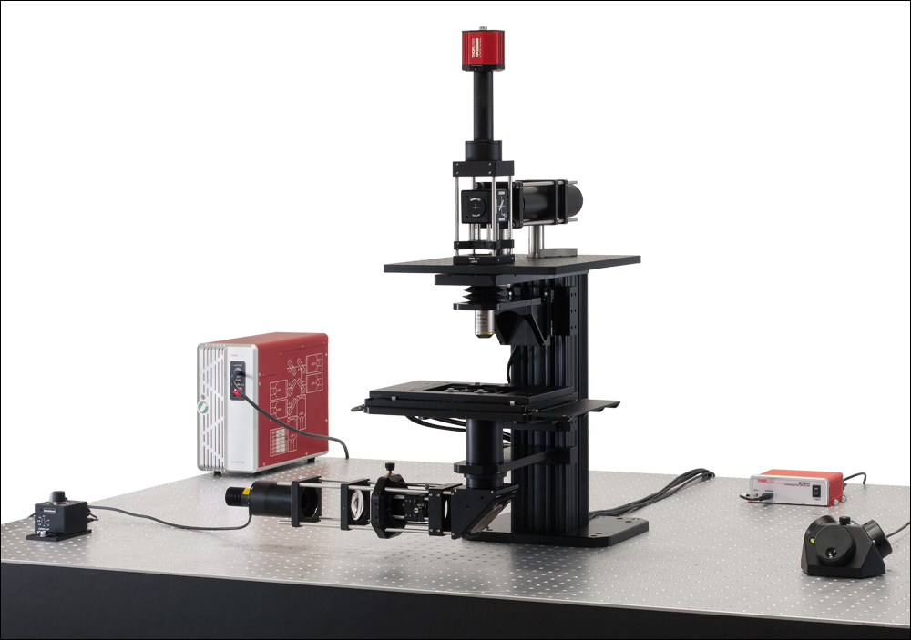
Click for Details
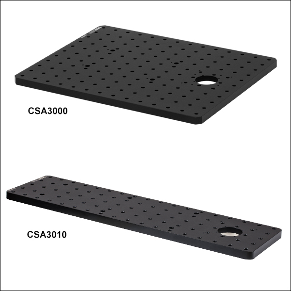
CSA3000 Used to Mount a Custom Epi-Illuminator and Widefield Viewing Apparatus with a sCMOS Camera
Click for Details
CSA3010 Used to Mount a Custom Epi-Illuminator and Widefield Viewing Apparatus with a sCMOS Camera
- Male D1N Dovetail on Bottom for Attachment to DIY Cerna Microscope Bodies
- Available in Two Sizes in Imperial and Metric Versions:
- Imperial: 14.00" x 11.00" or 18.00" x 4.60"
- Metric: 350.0 mm x 275.0 mm or 450.0 mm x 116.8 mm
- 1/4"-20 or M6 x 1.0 Mounting Holes
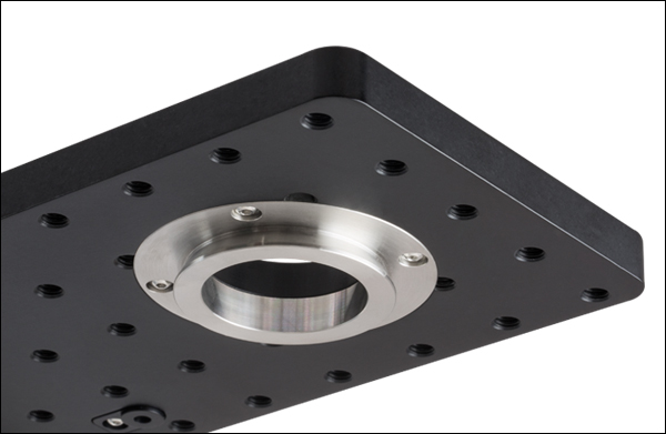
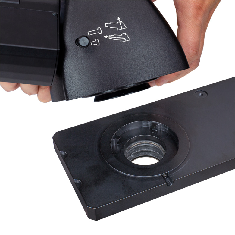
Click to Enlarge
Each breadboard has a male D1N dovetail on the bottom.
These black-anodized aluminum breadboard tops support user-designed widefield viewing apparatuses, epi-illumination pathways, and laser scanning pathways on top of upright Cerna microscopes. Each contains a Ø1.5" (Ø38.1 mm) through hole that is centered on a male D1N dovetail. This dovetail allows the breadboard to be connected directly to the epi-illumination arm of the microscope body, and it can also be used to stack the breadboard on top of an epi-illumination module. Additional details on the dovetail are available in the Microscope Dovetails tab.
The breadboards are available in two sizes. The larger version [Item # CSA3000(/M)] provides additional work surface, but protrudes past the sides of the epi-illumination arm, which may restrict approach angles around the objective for micromanipulators. The smaller version [Item # CSA3010(/M)] does not restrict approach angles and also has eight 4-40 taps around the Ø1.5" through hole for 30 mm and 60 mm cage systems.
In configurations where the breadboard is mounted directly on top of the epi-illumination arm, four M4 counterbores can be used to provide additional mounting stability.
| Item # | CSA3000 | CSA3000/M | CSA3010 | CSA3010/M |
|---|---|---|---|---|
| Dimensions (L x W) | 14.00" x 11.00" | 350.0 mm x 275.0 mm | 18.00" x 4.60" | 450.0 mm x 116.8 mm |
| Breadboard Thickness | 1/2" | 12.7 mm | 1/2" | 12.7 mm |
| Hole Size and Spacing | 1/4"-20 Tapped Holes on 1" Centers |
M6 x 1.0 Tapped Holes on 25 mm Centers |
1/4"-20 Tapped Holes on 1" Centers |
M6 x 1.0 Tapped Holes on 25 mm Centers |
| Number of Tapped Holes |
154 | 154 | 87 | 89 |
| Cage System Compatibility | - | Four 4-40 Taps for 30 mm Cage Systems Four 4-40 Taps for 60 mm Cage Systems |
||
| Click for Mechanical Drawing | ||||
| Dovetail | Male D1N | |||
| Material | Matte Black Anodized Aluminum | |||

 Zoom
Zoom
Click to Enlarge
Here, a white-light illumination path has been connected to the OPX2400 using our 60 mm cage system, and a GFP fluorescence path has been mounted on top of the OPX2400 via our WFA2002 epi-illuminator module.
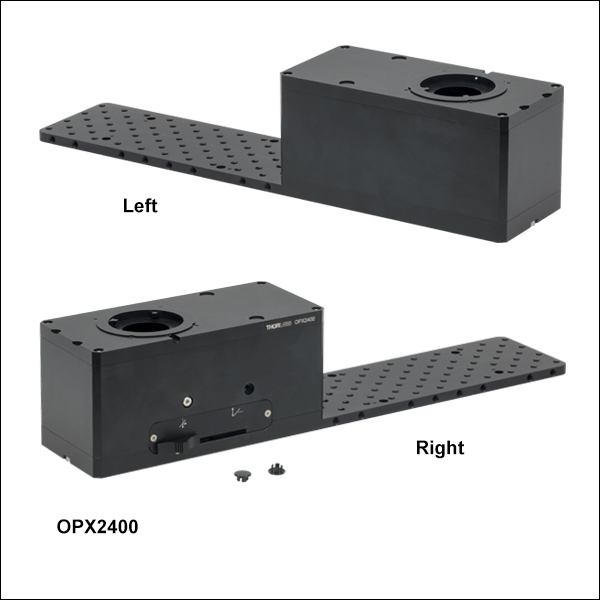
- Two-Position Slider to Combine or Switch Between DIY Optical Paths
- Slider has Internal SM2 Threads and Holds One 35 mm x 52 mm x 3 mm Optic
- Back Port has Internal SM2 Threads and Four 4-40 Taps for Our 60 mm Cage System
- Imperial and Metric Versions
- OPX2400: 10.16" x 3.94" Breadboard with Double-Density 1/4"-20 Tapped Holes
- OPX2400/M: 258 mm x 100 mm Breadboard with Double-Density M6 x 1.0 Tapped Holes
- Stackable Design with Female and Male D1N Dovetails on Top and Bottom, Respectively
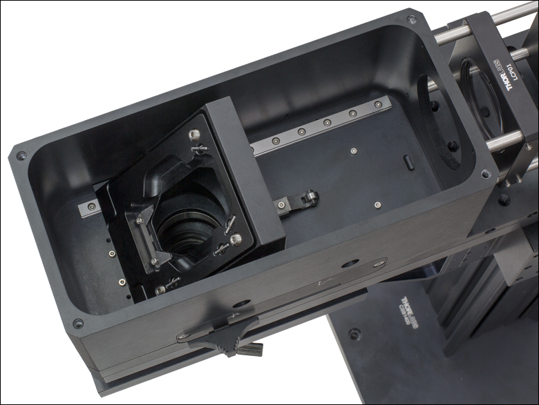
Click to Enlarge
Slider Located Above Objective
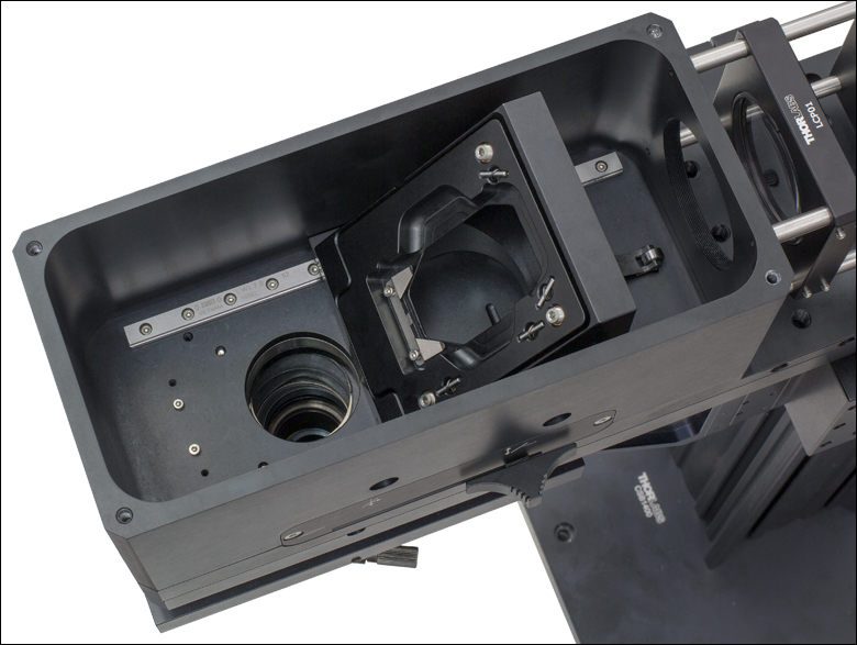
Click to Enlarge
Slider Not in Optical Path with Objective
The lid of the slider housing is opened by removing four cap screws with a 3 mm balldriver. The slider and the slider housing are internally SM2-threaded. Two stainless steel tracks and detents provide repeatable positioning.
The OPX2400(/M) Breadboard Top with Two-Position Slider adds a manually operated optic slider to the epi-illumination arm of a Cerna microscope body. By mounting a dichroic, beamsplitter, or mirror into the slider, users may combine or switch between widefield viewing, epi-illumination, and/or laser scanning pathways.
The optic slider has a clear aperture of Ø1.65" (Ø41.9 mm) and uses a leaf spring to retain a rectangular optic (minimum size: 34.9 mm x 51.9 mm x 2.8 mm; maximum size: 35.0 mm x 52.0 mm x 3.2 mm); the large aperture and optic size allow the entire aperture of the scan lenses above to be utilized. It has internal SM2 (2.035"-40) threads that face the back of the stationary housing, allowing a tube lens to be installed at a fixed distance from the dichroic. The back of the housing also has internal SM2 threads, as well as four 4-40 taps spaced for our 60 mm cage system.
In addition, a breadboard with sixty-eight 1/4"-20 (M6 x 1.0) through-tapped holes in a double-density hole pattern is included to support a home-built optical path. More 1/4"-20 (M6 x 1.0) tapped holes (sixteen on the imperial version and eighteen on the metric version) are located on the sides of the breadboard. Measured from the top of the breadboard, the beam height is 50.0 mm. Thorlabs manufactures Ø12 mm pedestal posts that center many of our 30 mm and 60 mm cage plates at this beam height, as illustrated in this photo, which provide structural support for large or heavy setups.
Thorlabs offers a 750 nm shortpass dichroic (Item # DMSP750B) and a protected silver mirror (Item # PFR14-P02) as stocked items. Beamsplitters and dichroics at additional cutoff wavelengths are available by contacting Tech Support. Once the optic is mounted, a 5/64" (2 mm) hex balldriver can be used to fine tune the optic slider's pitch and yaw adjusters. The slider may be locked in either position by tightening the included locking screw with a 3/32" balldriver. In the photo to the upper right, the locking screw is installed in the forward position.
In laser scanning Cerna systems, we recommend attaching the tube lens using the internal SM2 threads on the slider, since this will maximize the distance available along the throat depth to mount the objective and, if desired, non-descanned detectors.

 Zoom
ZoomTurret Position Sensor Software
Version 4.0 (October 11, 2019)
This software package contains the installation files for the GUI interface, driver, SDK, and support documentation. The software is compatible with Windows® 7 (64 bit) and Windows 10 (64 bit) systems.
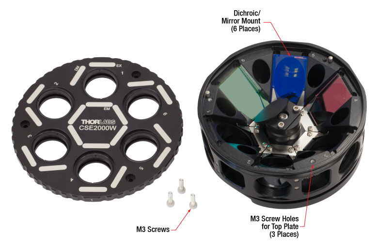
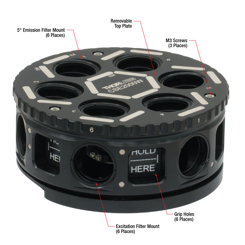
- Holds Up to Six Filter Sets in a Removable Turret without the Need for Filter Cubes
- Stackable Design with Female and Male D1N Dovetails on Top and Bottom, Respectively
- Directly Compatible with WFA3110 DIC Analyzer
- Monitor Filter Turret Position on a PC Using Included Software Package
- Four 4-40 Taps on Back for 60 mm Cage System
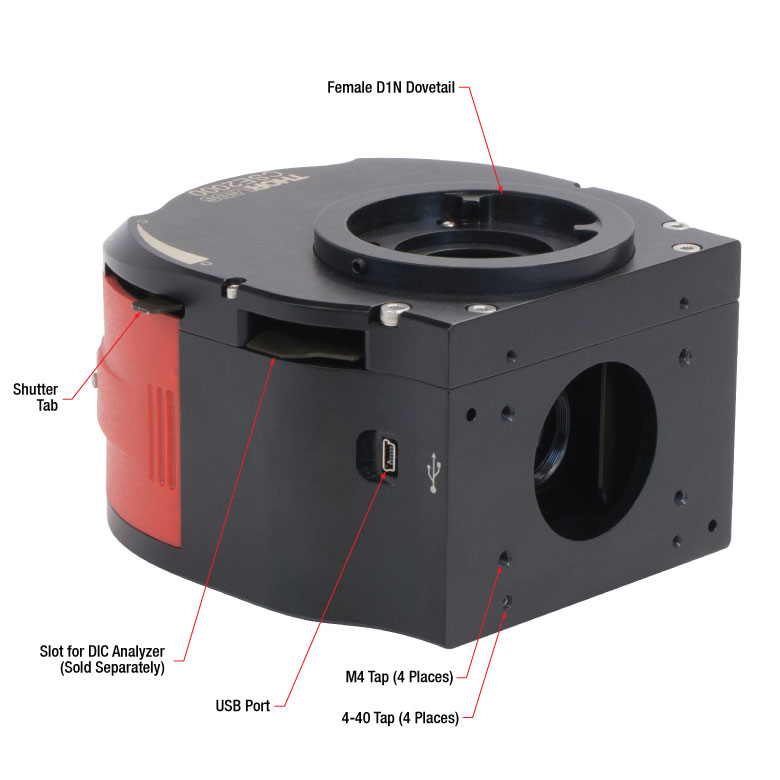
This Epi-Illuminator Module positions a rotating, removable turret (Item # CSE2000W, included with CSE2000 and sold separately below) in the epi-illumination pathway of a Cerna microscope. Fluorescence filter sets, beamsplitters, mirrors, and/or polarizing bandpass filters can be directly loaded into the turret without the need for filter cubes. Addition of the CSE2000 to a laser scanning microscope setup makes it possible to locate a region of interest with reflected light or fluorescence imaging, then perform laser-scanned measurements after switching filter sets. Turret position may be monitored remotely on a PC via included software; see the Software box at the top right to download the GUI installation files.
The module also has a slot that holds the WFA3110 DIC Analyzer, allowing it to be used in DIC-capable systems, but please note that this analyzer is only compatible with widefield DIC, not laser-scanned DIC. In addition, a tab opens and closes a shutter that blocks the optical path directed through the excitation filter.
Microscope Compatibility
With a female D1N dovetail on top and a male D1N dovetail on the bottom, these modules are designed to mate with Thorlabs' four-channel confocal microscopes, Cerna microscope bodies, the breadboard tops sold above, and other epi-illuminator modules. Additional details on dovetails are available in the Microscope Dovetails tab.
CSE2000 Epi-Illuminator Module
This stand-alone module features four 4-40 taps for 60 mm cage systems on the back side. This mechanical interface enables Thorlabs' extensive selection of 60 mm cage components to be used to build custom epi-illumination paths. To utilize the CSE2000 with an existing microscope featuring alternate dovetails, contact Tech Support for a custom solution.
CSE2000W Turret for Six Filter Sets
One CSE2000W Turret is included with each module, and additional turrets are available separately. The turret has six positions for filter sets, with each set consisting of up to two round filters (Ø1", <5.1 mm thick) and one rectangular optic (25 mm x 36 mm, 1 ± 0.1 mm thick). These filters are secured using the included SM1RR retaining rings and leaf springs, respectively. The emission filter slots are tilted by 5° in order to reduce unwanted back reflections in the light path that exits vertically.
Click to Enlarge
CSE2000W Filter Turret with Top Plate

Click to Enlarge
Once the front plate is removed, the turret can be safely removed from the epi-illuminator module by way of grip holes.
Click to Enlarge
The CSE2000 Epi-Illuminator Module features 4-40 taps to connect to a 60 mm cage system.
| Specifications |
|---|

 Zoom
Zoom
Click for Details
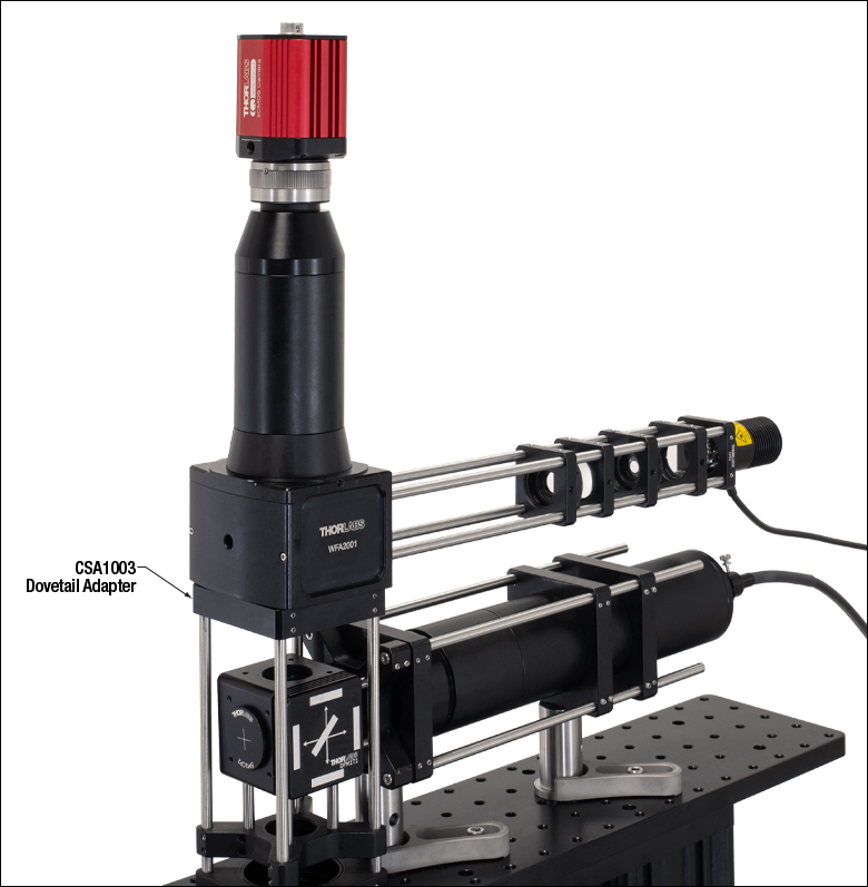
Here, the CSA1003 Dovetail Adapter is being used to connect a 60 mm cage system to the bottom of a WFA2002 Epi-Illuminator Module.
Click to Enlarge
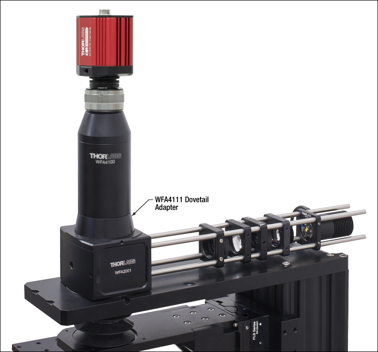
Here, the WFA4111 adapter is being used to mount an SM2 lens tube on top of an WFA2002 Epi-Illuminator Module.
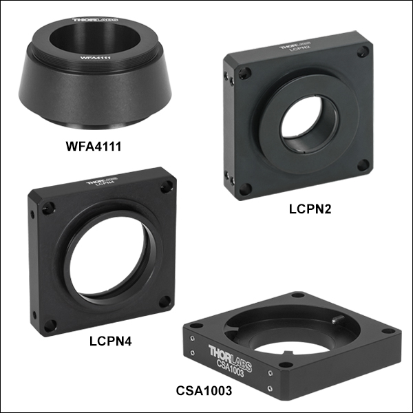
- Extend Versatility of Thorlabs' Lens Tube and Cage Construction Systems to DIY Cerna Systems
- LCPN2: Male D1N Dovetail, Internal SM30 Threads, and 30 mm and 60 mm Cage Compatibility
- LCPN3: Male D1N Dovetail, Female D5Y Dovetail, Internal SM30 Threads, and 60 mm Cage Compatibility
- WFA4111: Male D1N Dovetail, Internal M38 x 0.5 Threads, and External SM2 Threads
- SM2A59: Male D1N Dovetail and Internal SM2 Threads
- LCPN4: Male D1N Dovetail, Internal SM2 Threads, and 60 mm Cage Compatibility
- CSA1003: Female D1N Dovetail and 60 mm Cage Compatibility
These dovetail adapters integrate the D1N dovetail on the epi-illumination arm of a Cerna microscope body with Thorlabs' SM30 (M30 x 0.5) lens tubes, SM2 (2.035"-40) lens tubes, and 30 mm and 60 mm cage systems. Additionally, the WFA4111 and SM2A59 adapters feature internal M38 x 0.5 and SM2 threads, respectively, that can directly accept one of our infinity-corrected tube lenses. We also offer the LCPN3 trinocular port adapter, designed to allow Olympus trinoculars that have a male D5Y dovetail to be used with DIY Cerna systems.
The dovetail designations are specific to Thorlabs products; see the Microscope Dovetails tab for details.
| Item # | LCPN2 | LCPN3 | WFA4111 | SM2A59 | LCPN4 | CSA1003 |
|---|---|---|---|---|---|---|
| Dovetaila | Male D1N | Male D1N Female D5Y |
Male D1N | Female D1N | ||
| Threading | Internal SM30b | Internal M38 x 0.5c External SM2 |
Internal SM2d | Internal SM2e | None | |
| Internal Thread Depth | 0.76" (19.3 mm) | 0.48" (12.2 mm) | 0.53" (13.4 mm) | 0.15" (3.8 mm) | 0.45" (11.4 mm) | - |
| Cage Compatibility |
30 mm Cage System (4-40 Tapf, 4 Places) 60 mm Cage System (Ø6 mm Bore, 4 Places) |
60 mm Cage System (Ø6 mm Bore, 4 Places) |
Noneg | 60 mm Cage System (Ø6 mm Bore, 4 Places) |
||
| Clear Aperture | Ø1.10" (27.9 mm) | Ø1.47" (37.0 mm) | Ø1.69" (43.0 mm) | Ø1.74" (44.3 mm) | Ø1.50" (38.1 mm) | |
| Adapter Profile (Click for Drawing) |
||||||
| Material | Black-Anodized Aluminum | |||||