 Products Home / Optical Power and Energy Meters / Power and Energy Meter Interfaces with External Readout
Power and Energy Meter Interfaces with External Readout
- Compact Power Meter Interfaces with Various Output Connection Options
- Red C-Series Connector for Quick Sensor Exchange
- Ideal for Manufacturing Environments
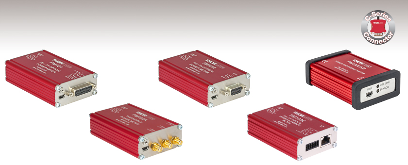
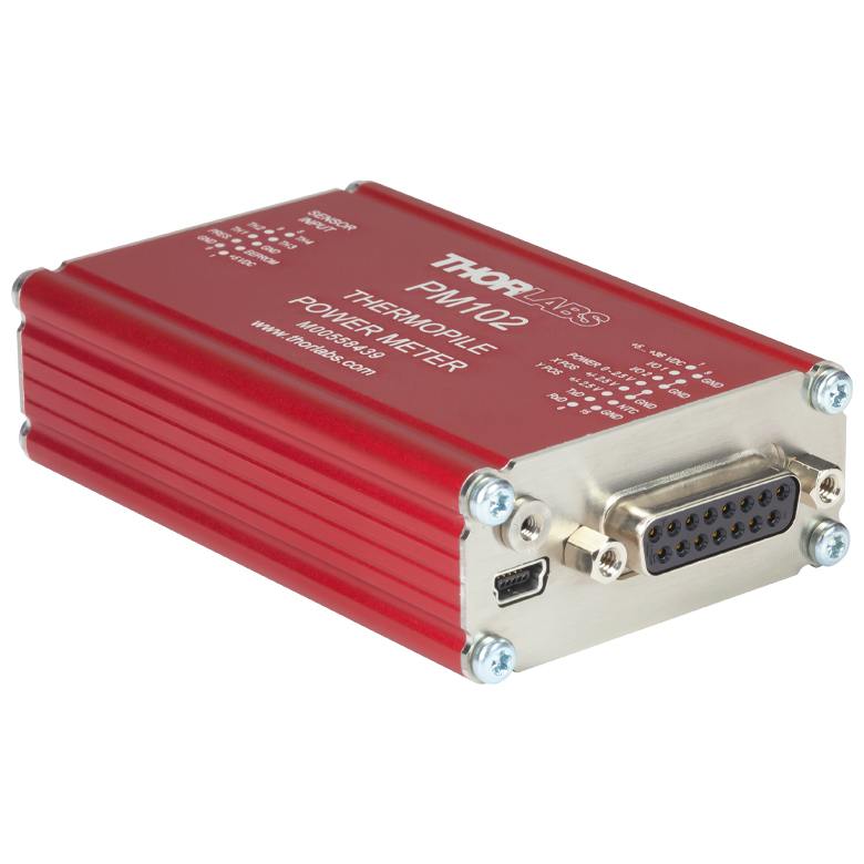
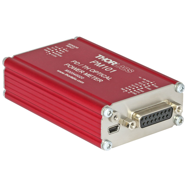
PM101
Photodiode and Thermal Power Sensor Interface with USB, RS232, and Analog Operation
Compatible with C-Type Sensors (Not Included with Console)
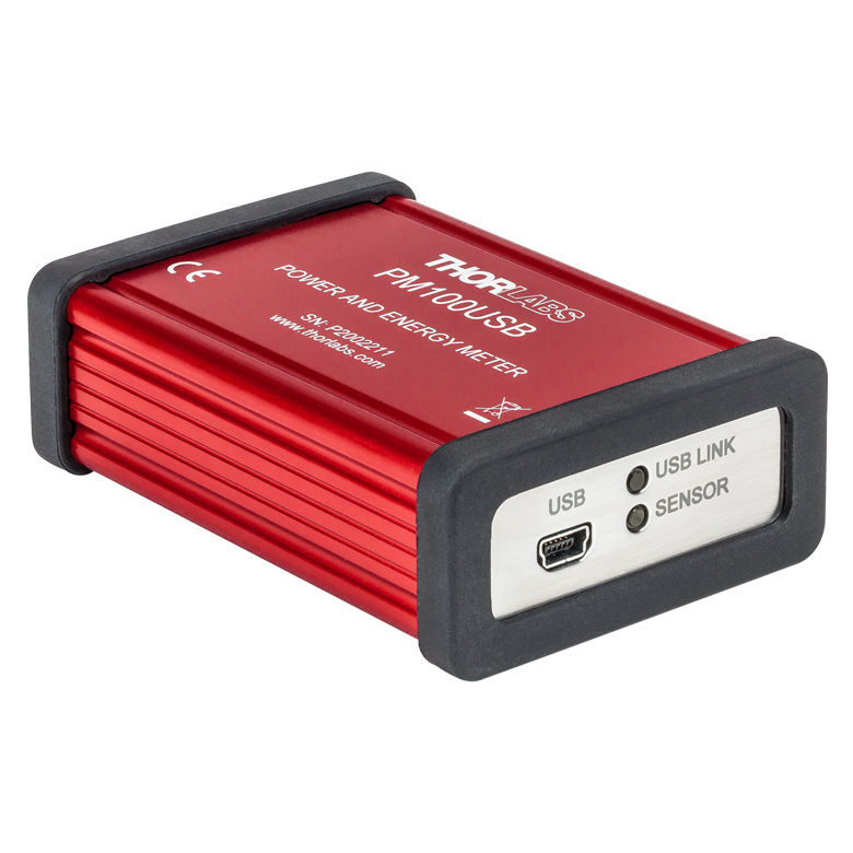
PM100USB
Power and Energy Sensor Interface with USB Operation
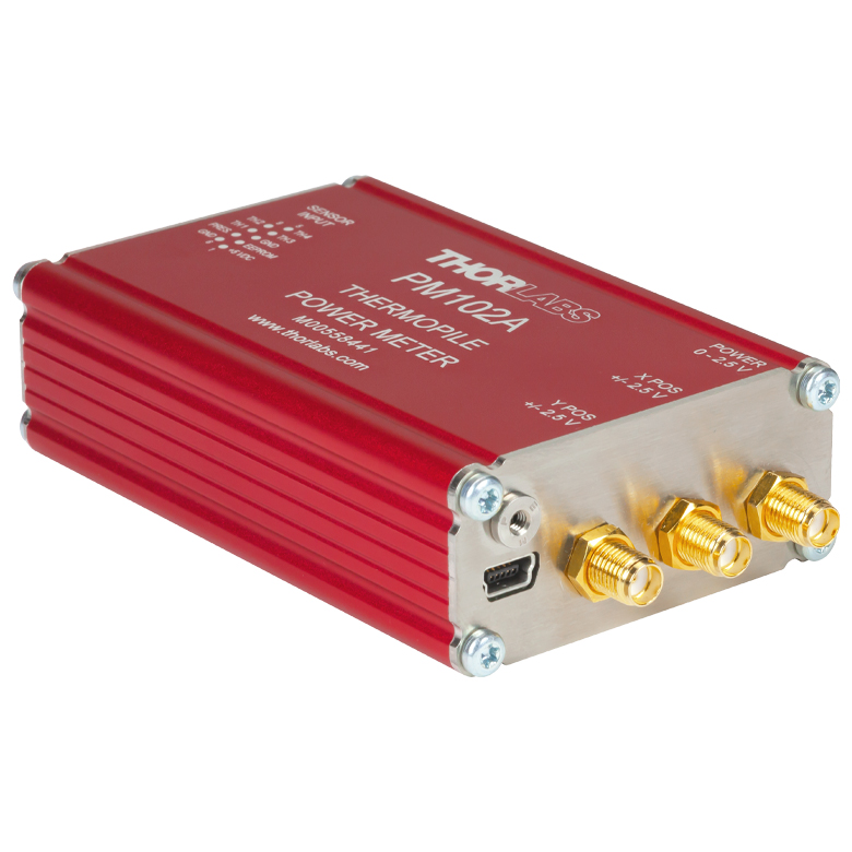
PM102A
Thermal Power and Position Sensor Interface with USB and Analog SMA Operation
PM101R
Photodiode and Thermal Power Sensor Interface with USB and RS232 Operation
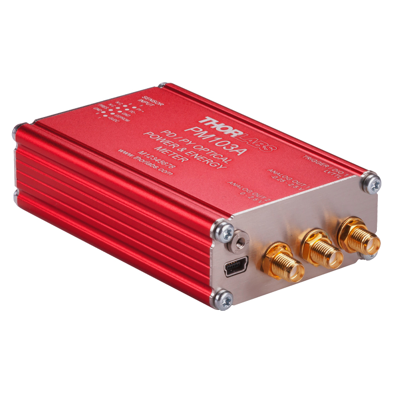
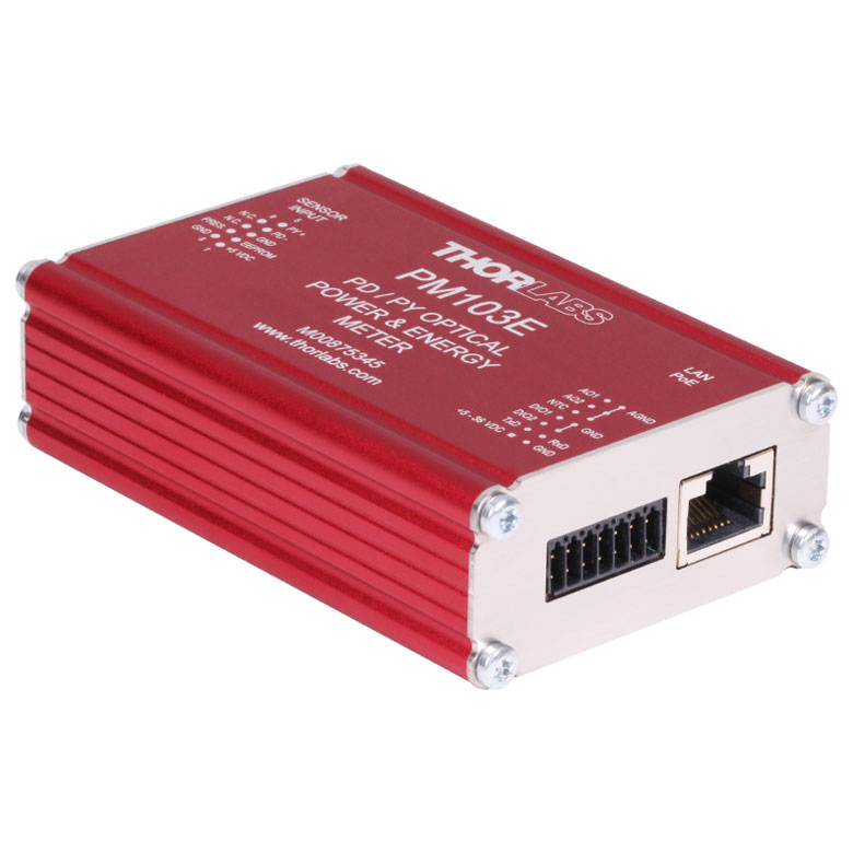
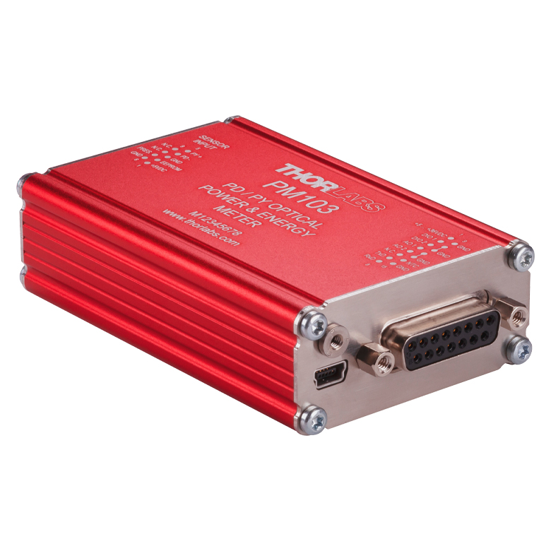
PM103E
Photodiode Power and Pyroelectric Energy Sensor Interface with Ethernet, RS232, and Analog Operation


Please Wait
| Power Meter Selection Guide |
|---|
| Sensors |
| Photodiode Power Sensors |
| Thermal Power Sensors |
| Thermal Position & Power Sensors |
| Pyroelectric Energy Sensors |
| Power Meter Consoles and Interfaces |
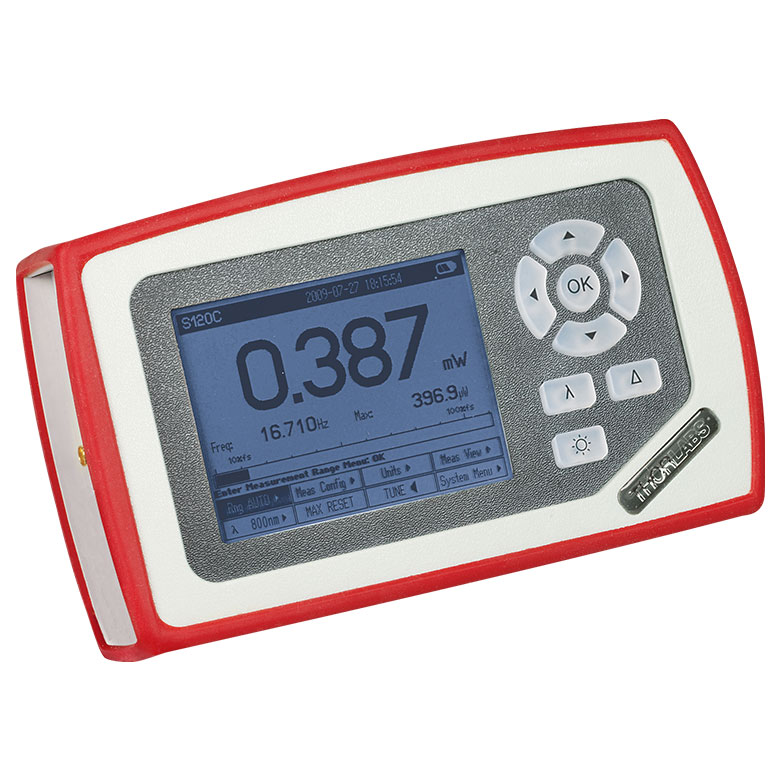
| Digital Handheld Console |
| Analog Handheld Console |
| Touchscreen Handheld Console |
| Dual-Channel Benchtop Console |
| USB Interfaces with External Readout |
| Complete Power Meters |
| Power Meter Bundles |
| Wireless Power Meters with Sensors |
| Compact USB Power Meters |
| Field Power Meters for Terminated Fibers |
Click to Enlarge
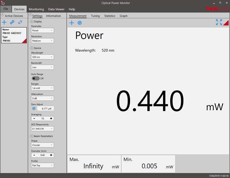
Optical Power Monitor Software GUI: Power Measurement
Click to Enlarge
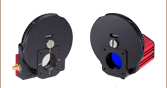
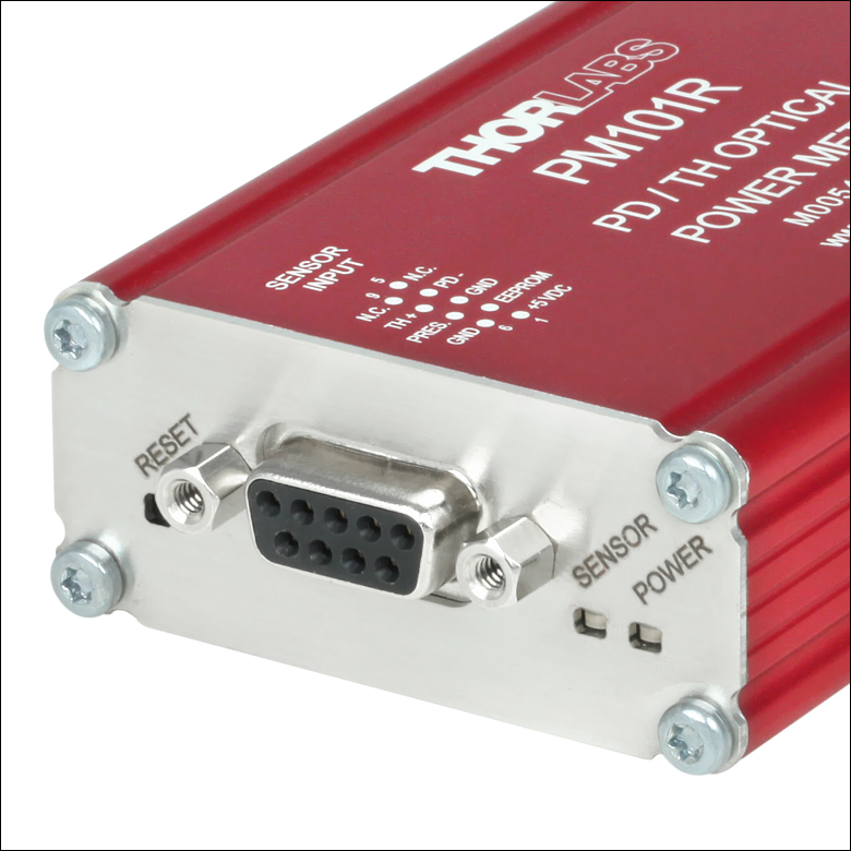
All power meter interfaces have a DE-9 input connector. The PM101, PM102, and PM103 series interfaces also feature status indicator LEDs and a reset button to reboot the interface.
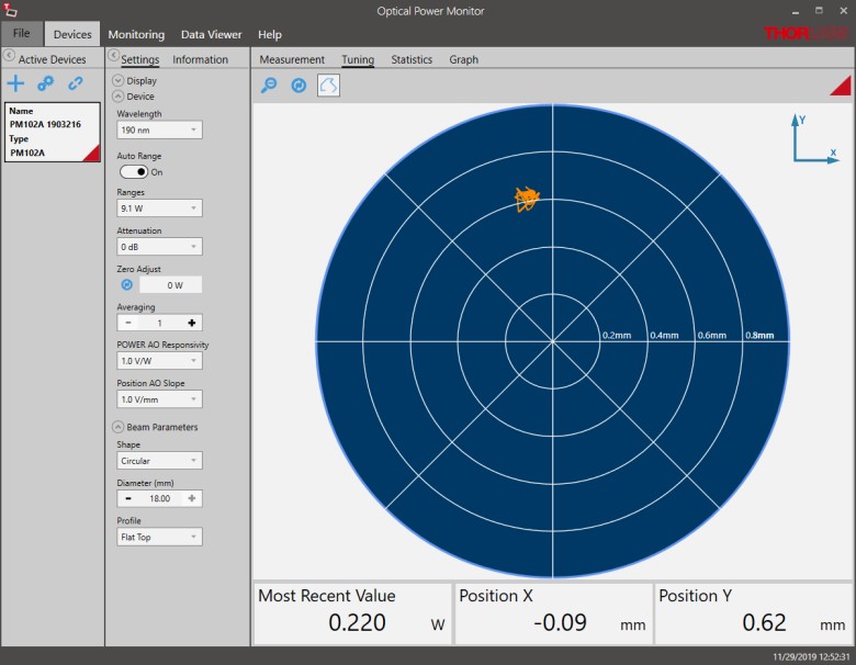
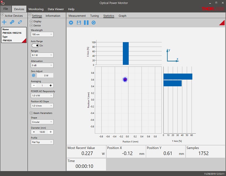
Click to Enlarge
Optical Power Monitor Software GUI:
Position Trace Using a Thermal Position & Power Sensor
Features
- Compact Interfaces to Enable PC Control of Power Meter Systems
- Compatible with Thorlabs' C-Series Sensors:
- PM101 Series: Photodiode and Thermal Power Sensors
- PM102 Series: Thermal Power and Thermal Position & Power Sensors
- PM103 Series: Photodiode Power and Pyroelectric Energy Sensors
- PM100USB: Photodiode Power, Thermal Power, and Pyroelectric Energy Sensors (Except for Item # ES408C)
- Optical Power Monitor PC Software Available (See Software Tab for Details)
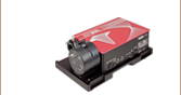
These interfaces provide communication between an attached sensor and a PC or other external control unit. They are designed to be controlled via an external device or operated autonomously using the analog output; there are no controls or display screens.
The PM101 series power interfaces are compatible with Thorlabs' C-Series photodiode and thermal power sensors, the PM102 series is suitable for use with our C-Series thermal power and thermal position & power sensors, and the PM103 series is suitable for use with our C-Series photodiode power and pyroelectric energy sensors. These interfaces support several options for control and digital readout, including USB 2.0, RS232, UART, analog output, and ethernet, depending on the model. The PM103 series is able to acquire data with a much higher readout rate of 100 kilosamples per second (kS/s) versus the maximum rate of 1 kS/s of the PM101 and PM102 series. Our PM100USB interface is controlled and provides digital readout via USB 2.0 only and is compatible with Thorlabs' C-Series photodiode, thermal power, and pyroelectric energy sensors, except for the ES408C fast pyroelectric energy sensor. See the table below and the Feature Comparison tab for a summary of technical data unique to each item #.
The compact housings used for these interfaces can be post-mounted using ECM100 or ECM225 aluminum clamps; alternatively, multiple units can be stacked using the EPS225 plastic clamp.
Sensor Compatibility
See the Sensor Selection tab or see below for our selection of power and energy sensors. All of the interfaces on this page allow "hot-swapping," or changing the connected sensor while the unit is turned on.
Computer Control
The power meter interface and connected sensor are controlled through a PC running Thorlabs' OPM Software (see the Software tab for details). The program offers configurable panels for the display of various numeric parameters that can be selected by the user, such as power or energy, their minimum or maximum values, and their units. The GUI also offers data logging with graphical display, tabular display for up to eight power meters, and a histogram representation of measurement statistics within a pre-determined period. Measured data can be stored as a .csv file. A driver set for integration with 3rd party software or customized applications is provided as well.
System Design
A selectable bandwidth of either 20 Hz or 100 kHz offers more flexibility and adaptability to specific measurement tasks while using photodiode sensors. The higher bandwidth is optimal for pulse detection; the lower bandwidth offers better accuracy. When used with our C-series thermal sensors, the interfaces can apply thermal time constant information stored in the sensor's connector to minimize the response time of the system.
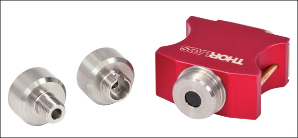
Fiber Photodiode Power Meter Option
The compact, integrated S15xC Series fiber photodiode sensors can be connected directly to a PM101x, PM103x, or PM100USB power meter interface to create a compact, single-unit fiber power meter. This avoids handling limitations due to cable movements, making this device ideal for multi-sensor applications that require remote control. The fiber sensors are compatible with exchangeable adapters for FC/PC, FC/APC, LC, SC, and ST fiber connectors; they are not compatible with our PM102 series interfaces.
Recalibration Services
Recalibration services are available for our thermal and photodiode power sensors, thermal power and position sensors, pyroelectric energy sensors, and power meter interfaces. We recommend recalibrating your Thorlabs sensor and interface as a pair; however, each may be recalibrated individually. To order this service for your photodiode power sensor, thermal power sensor, pyroelectric sensor, or interface, scroll to the bottom of the page and select the appropriate recalibration service Item # that corresponds to your sensor or interface. Recalibration of a thermal position sensor can be requested by contacting Tech Support. Recalibration of a single-channel power meter interface is included with the recalibration of a sensor at no additional cost.
Sensor Upgrade Service
Thorlabs' sensors and interfaces are not compatible with previous generation power meter consoles and sensor heads, respectively. We offer a sensor upgrade service if you want to use your existing sensors with a new power meter console or interface. Note: upgraded sensors will be incompatible with previous generation power meter consoles and new sensors converted to work with previous generation consoles will not be compatible with the power meter interfaces sold here. Please contact our Tech Support team for details.
| Quick Comparisona | ||||||||||||
|---|---|---|---|---|---|---|---|---|---|---|---|---|
| Item # | PM101 | PM101A | PM101R | PM101U | PM102 | PM102A | PM102U | PM103 | PM103A | PM103E | PM103U | PM100USB |
| USB Operation |  |
|
|
|
|
|
|
|
|
- | |
|
| Autonomous Operation with Analog Output | |
|
- | - | |
|
- | |
|
|
- | - |
| RS232 Operation | |
- | |
- | |
- | - | |
- | |
- | - |
| UART Operation | |
- | - | - | |
- | - | |
- | - | - | - |
| Ethernet Operation | - | - | - | - | - | - | - | - | - | |
- | - |
| Non-Volatile Memory | |
|
|
|
|
|
|
|
|
|
|
- |
| Configurable as Trigger Input/Output | - | - | - | - | - | - | - | |
|
|
- | - |
| Sensor Compatibility | ||||||||||||
| Photodiode Power | |
|
|
|
- | - | - | |
|
|
|
|
| Thermal Power | |
|
|
|
|
|
|
- | - | - | - | |
| Thermal Position & Power | - | - | - | - | |
|
|
- | - | - | - | - |
| Pyroelectric Energy | - | - | - | - | - | - | - | |
|
|
|
b |
| Sensor Compatibility | ||||
|---|---|---|---|---|
| Item # | PM101 Series | PM102 Series | PM103 Series | PM100USB |
| Sensor Compatibility | ||||
| Compatible Sensor Typesa | Photodiode Power and Thermal Power |
Thermal Power and Thermal Position & Power |
Photodiode Power and Pyroelectric Energy |
Photodiode Power, Thermal Power, and Pyroelectric Energyb |
| Max Photodiode Sensor Current | 5 mA | N/A | 10 mA | 5 mA |
| Max Thermal Sensor Voltage | 1 V | 1 V | N/A | 1 V |
| Max Thermal Position Sensor Voltage | N/A | 1 V | N/A | N/A |
| Max Pyroelectric Sensor Voltage | N/A | N/A | 200 V | 100 V |
| Photodiode Sensor Current Input | ||||
| Units | W, dBm, W/cm2, A | N/A | W, dBm, W/cm2, A | W, dBm, W/cm2, A |
| Current Measurement Range | 6 Decades: 50 nA, 500 nA, 5 µA, 50 µA, 500 µA, 5 mA; Range Selectable in W, Sensor Dependent |
N/A | 21 Ranges: nA: 2, 4, 10, 20, 40, 100, 200, 400; μA: 1, 2, 4, 10, 20, 40, 100, 200, 400; mA: 1, 2, 4, 10; Range Selectable in W, Sensor Dependent |
6 Decades: 50 nA, 500 nA, 5 µA, 50 µA, 500 µA, 5 mA; Range Selectable in W or A, Sensor Dependent |
| Current Display Resolution | 1 pA / Responsivity Value (A/W) | N/A | 1 pA / Responsivity Value (A/W) | 1 pA / Responsivity Value (A/W) |
| Current Measurement Uncertainty | ±0.2% Full Scale (5 µA - 5 mA) ±0.5% Full Scale (50 nA) |
N/A | ±0.2% Full Scale (400 nA - 10 mA) ±0.5% Full Scale (2 nA - 200 nA); Item # PM103E: ±0.2% Full Scale (100 nA - 10 mA) ±0.5% Full Scale (2 nA - 40 nA) |
±0.2% Full Scale (5 µA - 5 mA) ±0.5% Full Scale (50 nA) |
| Analog Bandwidth | DC - 100 kHz (Dependent on Sensor and Settings) |
N/A | DC - 150 kHz Item # PM103E: DC - 100 kHz (Dependent on Sensor and Settings) |
DC - 100 kHz (Dependent on Sensor and Settings) |
| Wavelength Correction | nm (A/W) | N/A | nm (A/W) (Item # PM103E: Dependent on Sensor)c |
nm (A/W) |
| Beam Area Setting | Diameter 1/e2 or Rectangular x,y | N/A | Diameter 1/e2 or Rectangular x,y | Diameter 1/e2 |
| AD Converter | 16 bit | N/A | 16 bit | 16 bit |
| Thermal Sensor Voltage Input | ||||
| Units | W, dBm, W/cm2, A | N/A | W, dBm, W/cm2, V | |
| Voltage Measurement Range | 9 Ranges: 2, 4, 10, 20, 40, 100, 200, 400, 1000 mV; Range Selectable in W, Sensor Dependent |
N/A | 4 Decades: 1, 10, 100, 1000 mV Range selectable in W or V, Sensor Dependent |
|
| Voltage Display Resolution | 1 µV / Responsivity Value (V/W) | N/A | 1 µV / Responsivity Value (V/W) | |
| Voltage Measurement Uncertainty | ±0.5% Full Scale (10 mV - 1 V) ±1% Full Scale (2 mV, 4 mV) |
N/A | ±0.5% Full Scale (10 mV - 1 V) ±1% Full Scale (1 mV) |
|
| Analog Bandwidth | DC - 10 Hz (Dependent on Sensor and Settings) |
N/A | DC - 10 Hz (Dependent on Sensor and Settings) |
|
| Wavelength Correction | Sensor Dependent; nm (V/W) | N/A | Sensor Dependent; nm (V/W) | |
| Beam Area Setting | Diameter 1/e2 or Rectangular x,y | N/A | Diameter 1/e2 | |
| Pyroelectric Sensor Voltage Input | ||||
| Units | N/A | N/A | J, J/cm2, W, dBm, W/cm2, V | J, J/cm2, W, W/cm2, V |
| Voltage Measurement Range | N/A | N/A | 13 Ranges: mV: 20, 40, 100, 200, 400; V: 1, 2, 4, 10, 20, 40, 100, 200; Ranges Selectable in J; Sensor Dependent |
4 Decades: 0.1, 1, 10, 100 V Range Selectable in J or V, Sensor Dependent |
| Voltage Display Resolution | N/A | N/A | 100 μV / Responsivity Value (V/W); Item # PM103E: 1 μV / Responsivity Value (V/W) |
100 µV / Responsivity Value (V/J) |
| Voltage Measurement Uncertainty | N/A | N/A | ±0.5% Full Scale (1 V - 200 V) ±1% Full Scale (20 mV, 400 mV); Item # PM103E: ±0.5% Full Scale (100 mV - 200 V) ±1% Full Scale (20 mV, 40 mV) |
±0.5% Full Scale |
| Trigger Level | N/A | N/A | 3% - 90% Full Scale | 0.1 % to 99.9 % Full Scale |
| Repetition Rate | N/A | N/A | Single Shot - 80 kHz, Dependent on Sensor |
3 kHz (Dependent on Sensor and Settings) |
| Wavelength Correction | N/A | N/A | Sensor Dependent; nm (V/W) | Sensor Dependent; nm (V/J) |
| Beam Area Setting | N/A | N/A | Diameter 1/e2 or Rectangular x,y | Diameter 1/e2 |
| AD Converter | N/A | N/A | 16 bit | 16 bit |
| Sensor Temperature Measurement | ||||
| Supported Temp. Sensor | Thermistor | |||
| Temp. Measurement Range | -10 to 120 °C | -10 to 120 °C | -10 to 120 °C Item # PM103E: -10 to 80 °C |
-10 to 80 °C |
| Sensor Interface | ||||
| Connector | DE-9 Female | |||
| Device Characteristics | |||||||||
|---|---|---|---|---|---|---|---|---|---|
| Item # | Dimensions (L x W x H) |
Operating Temperature |
Storage Temperature |
Weight | Display Type | Display Screens | Maximum Measurement Speed |
Battery | DC Input for Power |
| PM101 |
96.5 x 57.2 x 25.4 mm (3.80" x 2.25" x 1.00") |
-20 to 50 °C | -40 to 70 °C | 0.16 kg (0.35 lb) | External PC; Windows® Application or Driver Set |
Windows® Application Software Provided |
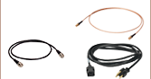
1000 S/s | No | USB Cable Provideda |
| PM101A | 100.0 x 57.2 x 25.4 mm (3.94" x 2.25" x 1.00") |
||||||||
| PM101R | 95.9 x 57.2 x 25.4 mm (3.78" x 2.25" x 1.00") |
||||||||
| PM101U | 93.6 x 57.2 x 25.4 mm (3.68" x 2.25" x 1.00") |
||||||||
| PM102 | 96.5 x 57.2 x 25.4 mm (3.80" x 2.25" x 1.00") |
0 to 40 °C | -40 to 70 °C | 0.16 kg (0.35 lb) | 1000 S/s | ||||
| PM102A | 100.0 x 57.2 x 25.4 mm (3.94" x 2.25" x 1.00") |
||||||||
| PM102U | 93.6 x 57.2 x 25.4 mm (3.68" x 2.25" x 1.00") |
||||||||
| PM103 | 96.5 x 57.2 x 25.4 mm (3.80" x 2.25" x 1.00") |
0 to 40 °C | -40 to 70 °C | 0.16 kg (0.33 lb) | 100 000 S/s | ||||
| PM103A | 100.2 x 57.2 x 25.4 mm (3.94" x 2.25" x 1.00") |
||||||||
| PM103E | 93.8 x 57.2 x 25.4 mm (3.69" x 2.25" x 1.00") |
Ethernet Cable Providedb |
|||||||
| PM103U | 93.6 x 57.2 x 25.4 mm (3.68" x 2.25" x 1.00") |
USB Cable Provideda |
|||||||
| PM100USB | 93.1 x 60.4 x 28.7 mm (3.67" x 2.38 " x 1.13") |
0 to 40 °C | -40 to 70 °C | 0.15 kg (0.33 lb) | 300 S/s | ||||
Compatible Sensor Overview
| Sensor Type | C-Series Photodiode Sensors, Photodiodes (Max 5 mA) |
C-Series Thermal Power Sensors, Thermopiles (Max 1 V) |
C-Series Thermal Position & Power Sensors |
C-Series Pyroelectric Sensors, Pyros (Max 100 V) |
|---|---|---|---|---|
| Compatible Interfaces | PM101, PM101A, PM101R, PM101U, PM103, PM103A, PM103E, PM103U, PM100USB |
PM101, PM101A, PM101R, PM101U, PM102, PM102A, PM102U, PM100USB |
PM102, PM102A, PM102U | PM103, PM103A, PM103E, PM103U, PM100USBa |
| Wavelength Ranges | 200 nm - 5.5 µm | 190 nm - 20 μm | 190 nm - 20 µm | 185 nm - 25 μm |
| Power / Energy Ranges | 100 pW - 20 W | 10 μW - 200 W | 0.5 mW - 50 W | 10 μJ - 15 J |
For a full list of the sensor head specifications please visit the Photodiode Power Sensors, Thermal Power Sensors, Thermal Position & Power Sensors, or Pyroelectric Energy Sensors pages. For other information, please contact Tech Support.
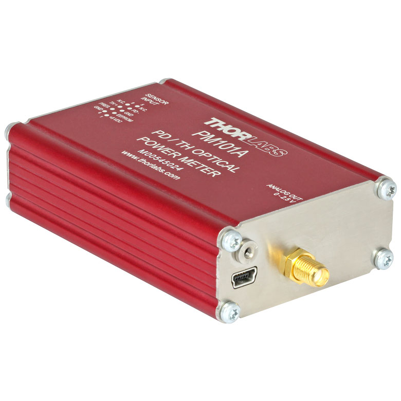
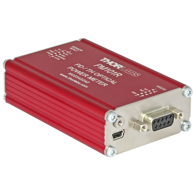
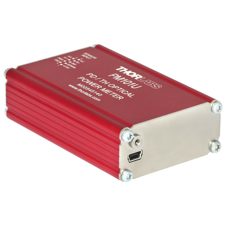
| Item # | PM101 | PM101A | PM101R | PM101U | PM102 | PM102A | PM102U |
|---|---|---|---|---|---|---|---|
| Photo (Click to Enlarge) |
 |
 |
 |
 |
 |
 |
 |
| Sensor Compatibility | |||||||
| Photodiode Sensors | |
|
|
|
- | - | - |
| Thermal Power Sensors | |
|
|
||||
| Thermal Position & Power Sensors | - | - | - | - | |||
| Pyroelectric Sensors | - | - | - | - | - | - | - |
| Connectors | |||||||
| C-Series Sensor DE-9 Connector | |
|
|
|
|
|
|
| USB Connector | Lockable | Lockable | Lockable | Lockable | Lockable | Lockable | Lockable |
| Serial DE-9 Connector | - | - | |
- | - | - | - |
| SMA Output Connector(s) | - | 1 Analog Power Output | - | - | - | 3 Ports: Power, X Position, and Y Position | - |
| DA-15 Universal Connector with 2 Auxiliary I/O Ports |
|
- | - | - | - | - | |
| Ethernet (RJ45) Connector | - | - | - | - | - | - | - |
| Phoenix DMC 0,5/7 Connector | - | - | - | - | - | - | - |
| Item # | PM103 | PM103A | PM103E | PM103U | PM100USB |
|---|---|---|---|---|---|
| Photo (Click to Enlarge) |
 |
 |
 |
 |
 |
| Sensor Compatibility | |||||
| Photodiode Sensors | |
|
|
|
|
| Thermal Power Sensors | - | - | - | - | |
| Thermal Position & Power Sensors | - | - | - | - | - |
| Pyroelectric Sensors | |
a |
|||
| Connectors | |||||
| C-Series Sensor DE-9 Connector | |
|
|
|
|
| USB Connector | Lockable | Lockable | - | Lockable | Not Lockable |
| Serial DE-9 Connector | - | - | - | - | - |
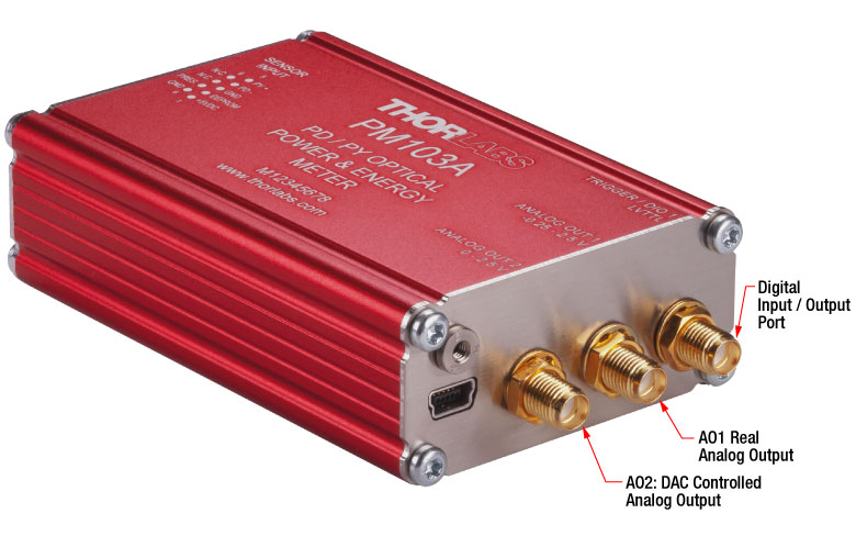
| SMA Output Connector(s) | - | 3 Ports: AO1, AO2, and Digital I/O (Configurable as External Trigger Input) | - | - | - |
| DA-15 Universal Connector with 2 Auxiliary I/O Ports | GPIO Ports Also Configurable as Trigger Input (Pin 2) or for Pass/Fail Analysis (Pin 3) | - | - | - | - |
| Ethernet (RJ45) Connector | - | - | - | - | |
| Phoenix DMC 0,5/7 Connector | - | - | - | - | |
Analog Output
The PM101 has two analog output ports assigned to pins in the DA-15 connector: AO1 and AO2. The signal from AO1 is a voltage value proportional to the selected measurement range, but is not wavelength or zero corrected; it is not sent through a DAC. AO2 delivers a measurement-range-independent voltage which is DAC controlled; the signal is proportional to a value set by the user through the OPM software or the SCPI/driver commands. The PM101A analog output functions in the same way as the AO2 output from the PM101, but access is provided via an SMA connector. See the manual for details.
The PM102 has three analog output ports assigned to pins in the DA-15 connector: POWER, X POS, and Y POS. The signal from POWER is a measurement-range-independent voltage which is DAC controlled; the signal is proportional to a value set by the user through the OPM software or the SCPI/driver commands. The signals from X POS and Y POS are voltage values proportional to the relative position of the beam on the sensor surface and a value set by the user. The PM102A analog outputs function in the same way as the analog outputs from the PM102, but access is provided via SMA connectors. See the manual for details.
The PM103 has two analog output ports assigned to pins in the DA-15 connector: AO1 and AO2. The signal from AO1 is a voltage value proportional to the selected measurement range, but is not wavelength or zero corrected; it is not sent through a DAC. AO2 delivers a measurement-range-independent voltage which is DAC controlled; the signal is proportional to a value set by the user through the OPM software or the SCPI/driver commands. The PM103A has two analog output ports with SMA output connectors, which match the function of AO1 and AO2 of the PM103 respectively. The PM103E also includes the same AO1 and AO2 analog output functionality from pins #13 and #11 respectively of the Phoenix DMC 0,5/7 connector. See the manual for details.
The PM101, PM102, PM103, PM101A, PM102A, PM103A, and PM103E can be operated autonomously if only an analog output is required; only power needs to be supplied to the unit.
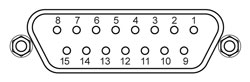
Sensor Connector (All Models)
D-Type Female
| Sensor Connector Pin Assignments | ||||
|---|---|---|---|---|
| Pin | PM101 Series | PM102 Series | PM103 Series | PM100USB |
| 1 | +5 V (Drive Max 100 mA from this Pin) | +5 V (Drive Max 50 mA from this Pin) | ||
| 2 | DO NOT USEa | |||
| 3 | Analog Ground for PD Anode, Thermal Sensor, and NTC |
Analog Ground for Thermal Sensor and NTC |
Analog Ground for PD Anode, Pyroelectric Sensor, and NTC |
Analog Ground for PD Anode, Thermal, and Pyroelectric Sensor |
| 4 | PD Cathode | Thermal Sensor Input Quadrant 3 | PD Cathode | PD Cathode |
| 5 | N.C. | Thermal Sensor Input Quadrant 4 | Pyroelectric Sensor Input | Pyroelectric Sensor + |
| 6 | Digital Ground for EEPROM and 5 V Output | |||
| 7 | Present: Sensor Recognition, NTC Input. Connect this Pin via a 1 kΩ to 10 kΩ Resistor to Pin 3 (AGND) to Enable a Custom Sensor |
|||
| 8 | Thermal Sensor + | Thermal Sensor Input Quadrant 1 | N.C. | Thermal Sensor + |
| 9 | N.C. | Thermal Sensor Input Quadrant 2 | N.C. | N.C. |
USB 2.0 Port (All Models Except Item # PM103E)
USB Type Mini-B
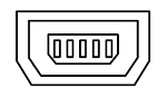
USB Type Mini-B to Type A Cable Included
| Item # | PM101 Series | PM102 Series | PM103 Series | PM100USB |
|---|---|---|---|---|
| Remote Interface Type | USB 2.0a | |||
| Connector | Mini-B USB, Lockable | Mini-B USB, Lockable | Mini-B USB, Lockable | Mini-B USB |
| Measurement Speed | Up to 1000/s | Up to 500/s | 1 kS/s + 100 kS/s Bulk Mode | N/A |
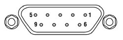
Serial DA-15 Connector (PM101, PM102, and PM103 Only)
DA-15 Female
| DA-15 Connector Pin Assignments | |||
|---|---|---|---|
| Pin | PM101 | PM102 | PM103 |
| 1 | Pin for Alternative Power Supply with 5 to 36 VDC | ||
| 2 | I/O 1 General Digital Input/Output Port; 3 V Logic (Output), 5 V Tolerant for Input | ||
| 3 | I/O 2 General Digital Input/Output Port; 3 V Logic (Output), 5 V Tolerant for Input | ||
| 4 | Analog Output; -0.25 to +2.5 V per Measurement Range |
Software Configurable Analog Output for Beam Power; 0 to 2.5 V |
Analog Output; -0.25 to +2.5 V per Measurement Range |
| 5 | Software Configurable Analog Output; 0 to 2.5 V |
Software Configurable Analog Output for X-Position; -2.5 to 2.5 V |
Software Configurable Analog Output; 0 to 2.5 V |
| 6 | N.C. | Software Configurable Analog Output for Y-Position; -2.5 to 2.5 V |
N.C. |
| 7 | RS232 to PC Terminal RxD | ||
| 8 | RS232 to PC Terminal TxD | ||
| 9 | Power Supply Ground | ||
| 10 | Ground | ||
| 11 | Ground | ||
| 12 | Ground | ||
| 13 | Ground | ||
| 14 | NTC Thermistor Input; Measurement Range 0.1 to 100 kΩ | ||
| 15 | RS232 Signal Ground | ||
| Item # | PM101 | PM102 | PM103 |
|---|---|---|---|
| RS232 Communication | |||
| DA-15 Pins | 7 and 8 | ||
| Baud Rate | 9600 - 230400 Bit/s Default: 115200 Bit/s |
||
| Settings | N1S | ||
| Measurement Speed | Up to 200/s | Up to 200/s | 200/s + 100 kS/s Bulk Mode |
| Analog Output, Configurable | |||
| DA-15 Pin(s) | 5 | 4 (Power), 5 (X-Position), and 6 (Y-Position) | 5 |
| Signal | Gain Signal Configurable | Power (Configurable in V/W), X-Position & Y-Position (Configurable in V/µm) |
Gain Signal Configurable |
| Voltage Range | 0 to 2.5 V | Power: 0 to 2.5 V; Positions: -2.5 V to +2.5 V |
0 to 2.5 V |
| Accuracy | ±1% | ||
| Bandwidth | 1 kHz | ||
| Analog Output, Not Corrected | |||
| DA-15 Pin | 4 | N/A | 4 |
| Signal | Amplified Input Signal - Not Corrected | N/A | Amplified Input Signal - Not Corrected |
| Voltage Range | 0 to 2.5 V | N/A | -0.25 to 2.5 V |
| Accuracy | ±3% | N/A | ±3% |
| Bandwidth | Up to 100 kHz, Dependent on Sensor and Settings |
N/A | Up to 1 MHz, Dependent on Sensor and Settings |
| Auxiliary Temperature Control | |||
| DA-15 Pin | 14 | ||
| Supported Tempearature Sensor | Thermistor NTC 0.1 - 100 kΩ, B-Value: 1000 - 9999 K | ||
| Temperature Measurement Range | -40 °C to +200 °C (NTC Dependent) | ||
| Digital Control Pins I/O | |||
| DA-15 Pins | 2 and 3 | ||
| Signal | 2 x GPIO | 2 x GPIO | 2 x GPIO or Configurable as Trigger Input/Output, Pass/Fail Analysis |
| Power Management | |||
| DA-15 Pins | 1 and 9 | ||
| DC Input | +5 VDC to +36 VDC | ||
Serial DE-9 Connector (PM101R Only)
DE-9 Female
| Item # | PM101R |
|---|---|
| RS232 Communication | |
| DE-9 Pins | 2 and 3 |
| Baud Rate | 9600 - 230400 Bit/s Default: 115200 Bit/s |
| Settings | N1S |
| Measurement Speed | Up to 200/s |
| DE-9 Connector Pin Assignments | |
|---|---|
| Pin | PM101R |
| 1 | N.C. |
| 2 | RS232 to PC Terminal RxD |
| 3 | RS232 to PC Terminal TxD |
| 4 | N.C. |
| 5 | Ground |
| 6 | N.C. |
| 7 | N.C. |
| 8 | N.C. |
| 9 | N.C. |
SMA Connector(s) (PM101A, PM102A, and PM103A Only)
| Item # | PM101A | PM102A | PM103A |
|---|---|---|---|
| SMA Connector(s) (Click to Enlarge) |
 |
 |
 |
| Analog Output, Configurable | |||
| SMA Connector(s) | Analog Output | Power, X-Position, and Y-Position | AO2 |
| Signal | Gain Signal Configurable | Power (Configurable in V/W), X-Position & Y-Position (Configurable in V/μm) |
Gain Signal Configurable |
| Voltage Range | 0 to 2.5 V | Power: 0 to 2.5 V; Positions: -2.5 V to +2.5 V |
0 to 2.5 V |
| Accuracy | ±1% | ||
| Bandwidth | 1 kHz | ||
| Analog Output, Not Corrected | |||
| SMA Connector | N/A | N/A | AO1 |
| Signal | N/A | N/A | Amplified Input Signal - Not Corrected |
| Voltage Range | N/A | N/A | -0.25 V to 2.5 V |
| Accuracy | N/A | N/A | ±3% |
| Digital Control I/O | |||
| SMA Connector | N/A | N/A | Digital I/O |
| Signal | N/A | N/A | GPIO or Configurable as Trigger Input/Output |
Phoenix DMC 0,5/7 and Ethernet RJ45 Connectors (Item # PM103E Only)
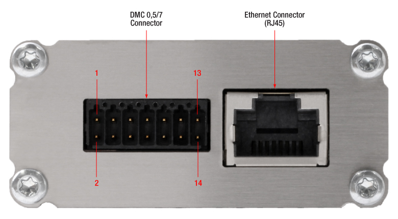
Click to Enlarge
PM103E Interface Connectors
| Phoenix DMC 0,5/7 Connector Pin Assignments | |
|---|---|
| Pin | PM103E |
| 1 | Pin for Alternative Power Supply with 5 to 36 VDC |
| 2 | Power Supply Ground/ Digital Ground |
| 3 | RS232; Connect to PC Terminal RxD (PC DE-9 Pin 2) |
| 4 | RS232; Connect to PC Terminal TxD (PC DE-9 Pin 3) |
| 5 | I/O 2 General Digital Input/Output Port; 3 V Logic (Output), 5 V Tolerant for Input |
| 6 | Digital Ground |
| 7 | I/O 1 General Digital Input/Output Port; 3 V Logic (Output), 5 V Tolerant for Input |
| 8 | Digital Ground |
| 9 | NTC Thermistor Input; Measurement Range 0.1 kΩ to 100 kΩ |
| 10 | Analog Ground |
| 11 | Software Configurable Analog Output; 0 V to 2.5 V |
| 12 | Analog Ground |
| 13 | Analog Output; -0.25 V to +2.5 V per Measurement Range |
| 14 | Analog Ground |
| Item # | PM103E |
|---|---|
| RS232 Communication | |
| DMC 0,5/7 Pins | 3 and 4 |
| Baud Rate | 9600 - 256000 Bit/s Default: 115200 Bit/s |
| Settings | N1S |
| Measurement Speed | 200 S/s + 100 kS/s Bulk Mode |
| Item # | PM103E |
|---|---|
| Remote Interface Type | Ethernet |
| Connector | RJ45 |
| Measurement Speed | 1 kS/s + 100 kS/s Bulk Mode |
RS232 Serial Connections for CABRU15 USB to Serial Flying Leads Adapter Cable
CABRU15 USB Type A to Serial Adapter

| Cable Lead Assigments | |
|---|---|
| Lead Color | Function |
| WHITE | +5 V |
| BROWN | GND |
| GREEN | RxD |
| YELLOW | TxD |
| DA-15 Pin to Lead Assignments | DE-9 Pin to Lead Assignments | Phoenix DMC 0,5/7 Pin to Lead Assignments | |||
|---|---|---|---|---|---|
 |
 |
 |
|||
| Pin | PM101, PM102, PM103 | Pin | PM101R | Pin | PM103E |
| 1 | +5 V (WHITE) | 2 | TxD (YELLOW) | 1 | +5 V (WHITE) |
| 7 | TxD (YELLOW) | 3 | RxD (GREEN) | 2 | GND (BROWN) |
| 8 | RxD (GREEN) | 5 | GND (BROWN) | 3 | TxD (YELLOW) |
| 9 | GND (BROWN) | 1, 4, 6-9 | N.C. | 4 | RxD (GREEN) |
| 2-6,10-15 | N.C. | 5-14 | N.C. | ||
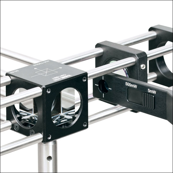
Standard Photodiode Sensor Mounting Options
The compact design of Thorlabs' Standard Photodiode Sensors allows easy integration into existing setups. Typical mounting configurations including post, cage, and lens tube options are available. Shown on this page are several different choices for mounting these sensors.
The Standard Photodiode Sensors are compatible with all S120-xx series fiber adapters. FC/PC and SMA adapters are shown on the right. Adapters for FC/APC, SC, LC, and ST connections are also available.

Flip mounts are convenient for quick power measurements from a static location. The sensor can be placed in the path of the laser beam for the power measurement and flipped down during normal operation of the system.
FM90(/M) Right-Angle Flip Mounts are shown to the right. Thorlabs also offers the TRB1(/M) Articulating Post Mount. The lockable articulating mount offers almost unlimited positioning of the sensor head.
The Standard Photodiode Sensors also feature externally SM1-threaded connections on the front face. The SM1 threading provides easy mounting to 1" lens tube systems and quick-release mounts.
Shown to the right are the KB1P(/M) Quick-Release Post Mount and QRC1A Quick-Release 30 mm Cage Mount. Both mounts feature SM1-threaded connections to the sensor heads.
Note: Due to the thickness of the S12xC sensor, the QRC1A and CP44F (shown below) quick release mounts can only be fully removed from the cage system by backing them off an open end. The two mounts are easily removed from the cage system if only three cage rods are used. See the picture on the right.
Thorlabs also offers the CP44F 30 mm Cage Plates with Quick-Release Mounts. These mounts feature magnetically coupled front and back plates for easy and repeatable mounting.
Note: Like the QRC1A, the CP44F cannot be removed from a closed cage system.
Slim Photodiode Sensor Mounting Options
Thorlabs' Slim Photodiode Sensors are designed to fit into space-restricted environments such as 30 mm cage systems and optic-dense free-space arrangements.
Shown to the right is a S130C Sensor inserted into a 30 mm cage system. The application shown highlights the ease with which the sensor can be inserted into the cage, and the minimal space needed to take a power measurement.
The Slim Photodiode Sensors may also be mounted on a TRB1(/M) Articulating Mount. This mount allows repeatable insertion of the sensor into tight optic arrangements. After the measurement is made, the sensor may be rotated out of the beam path for normal operation.
Compact Slim Photodiode Sensor Mounting Options
Thorlabs' Compact Slim Photodiode Sensors are designed to fit into even tighter spaces such as 16 mm cage systems, our slotted Ø1/2" lens tubes, and other optic-dense free-space arrangements.
Shown to the right is an S116C Sensor inserted into a 16 mm cage system. The application shown highlights the ease with which the sensor can be inserted into the cage, and the minimal space needed to take a power measurement.
The compact slim photodiode sensor has two 8-32 (M4) taps for post mounting. One tap mounts the sensor horizontally, as seen to the right, and one allows it to be mounted vertically. The sensor may also be mounted on a TRB1(/M) Articulating Mount. This mount allows repeatable insertion of the sensor into tight optic arrangements. After the measurement is made, the sensor may be rotated out of the beam path for normal operation.
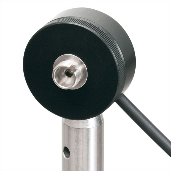
Microscope Slide Photodiode Sensor Mounting Options
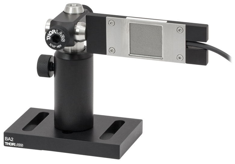
S170C Mounted on a Post
The S170C may be post mounted via the 8-32 (M4 x 0.7) tap in the side of the housing.
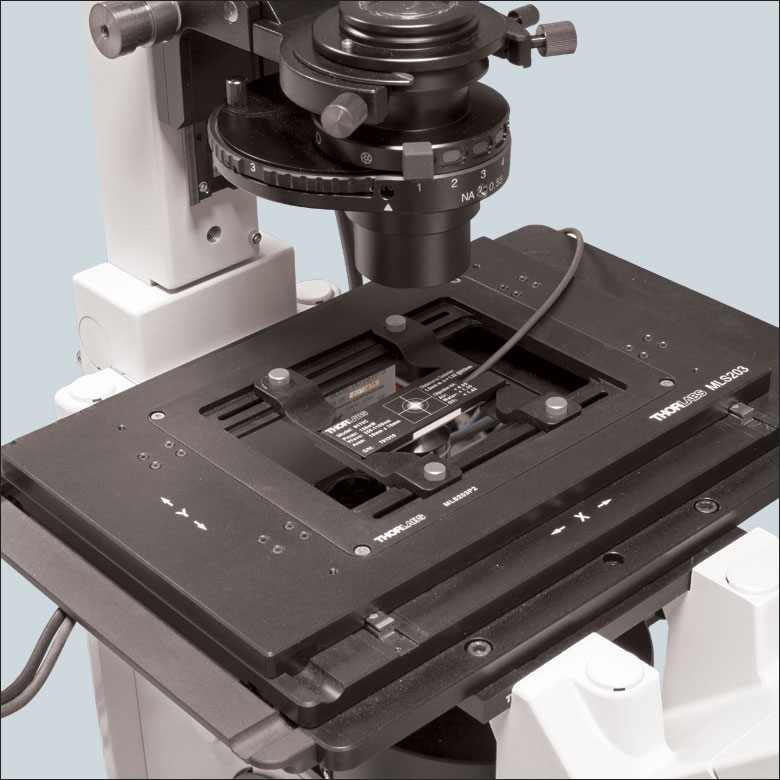
Thorlabs' Microscope Slide Power Sensors are designed so they can be mounted directly in a microscope slide holder. The 76.0 mm x 25.2 mm x 5.0 mm sensor head has the same footprint as a standard microscope slide and is compatible with most standard upright and inverted microscopes. The photo to the right shows the S170C power sensor flipped over so that the engraved back of the housing can be used for alignment.
The S170C, S171C, and NS170C power sensors also have an 8-32 (M4 x 0.7) tap for post mounting. In the photo to the far right, an RA90(/M) is used with two Ø1/2" posts to mount the S170C sensor head in a horizontal orientation.
Integrating Sphere Photodiode Sensor Mounting Options
Thorlabs' Integrating Sphere Photodiode Sensor provides a low loss cavity for diverging, non-uniform, or off-axis beam measurements. These integrating spheres are ideal for all fiber-based applications due to the beam divergence at the end of the fiber.
Shown to the right is an S140C Integrating Sphere with S120-FC Fiber Adapter. Also shown is an S140C with an S140-BFA Bare Fiber Adapter. The Bare Fiber Adapter features a mounting clamp and light shield to decrease interference from ambient light.
Compact Fiber Photodiode Sensor Mounting Options
Thorlabs' Compact Fiber Photodiodes are the ideal choice for a portable, fiber-coupled power meter. The S15xC sensors are compatible with a wide variety of fiber connections. PM20-xx adapters are available to couple FC, APC, SMA, ST, SC, and LC connectors with the sensors. Shown to the right is an S150C Sensor with FC and SMA connector adapters.
Shown to the far right is a PM100D console with S150C sensor connected to a FC connectorized optical fiber. This setup is ideal for portable use in the lab or in the field.
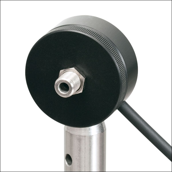
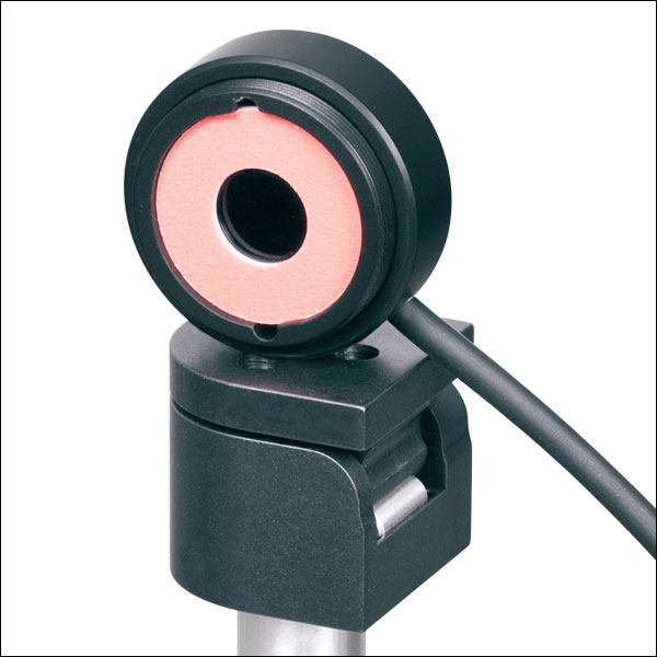
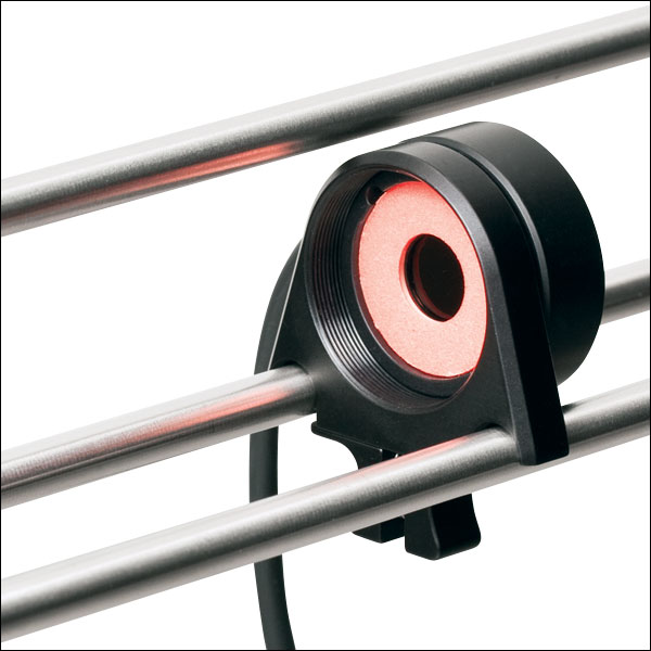
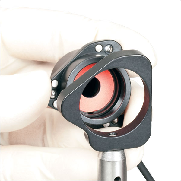
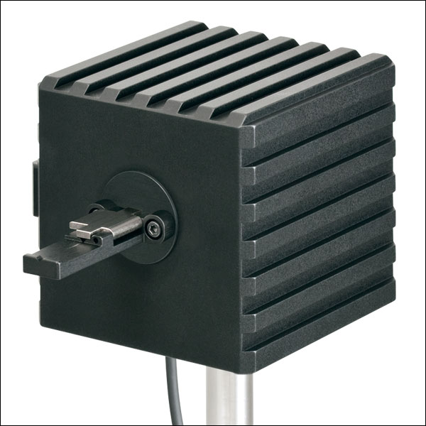
Pyroelectric Energy Sensor Mounting Options

Thorlabs' Pyroelectric Energy Sensors are ideal for measuring pulsed sources. These pyroelectric sensors provide direct energy readings for those sources. The sensors are designed to handle medium- to high-energy pulses from excimer, YAG, and other high-power lasers.
Each sensor ships with an insulating adapter for Ø1/2" post mounting, and they are also compatible with our 30 mm cage system, as shown to the right.
Compatible Power Meters
- Consoles:
- PM100A Analog Power and Energy Meter Console
- PM100D Digital Power and Energy Meter Console
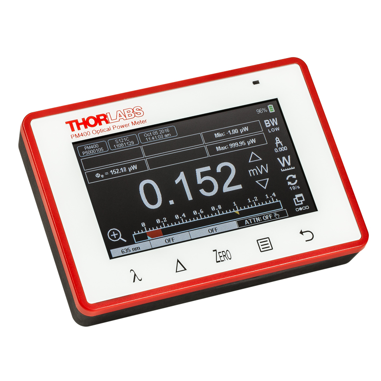
- PM400 Capacitive Touchscreen Power and Energy Meter Console
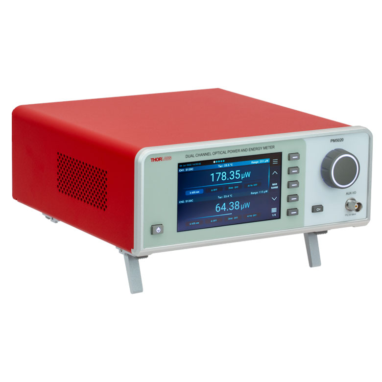
- PM5020 Dual-Channel Benchtop Optical Power and Energy Meter Console (Version 4.0 or Later)
- Complete Power Meters:
- PM160, PM160T, and PM160T-HP Wireless Handheld Power Meters with Bluetooth® Technology
- PM16 Series Compact USB Power Meters
- PM60 and PM61 Fiber Optic Power Meter Series (Version 6.0 or Later)
- Interfaces:
- PM101 Series Power Meter Interfaces with External Readout (Version 2.0 or Later)
- PM102 Series Power Meter Interfaces with External Readout (Version 2.1 or Later)
- PM103 Series Power Meter Interfaces with External Readout (Version 3.0 or Later)
- PM100USB USB Interface Digital Power and Energy Meter
Optical Power Monitor
The Optical Power Monitor GUI software features power measurement, readout from up to eight power meters, and remote wireless operation.
For details on specific software features, please see the user manual.
Users interested in the legacy Power Meter Software can find it by visiting the software page.
The PM101 Series Power Meters are only compatible with version 2.0 or later. The PM102 Series Power Meters are only compatible with version 2.1 or later. The PM103 Series Power and Energy Meters are only compatible with version 3.0 or later. The PM5020 Console is only compatible with version 4.0 or later. The PM60 and PM61 Power Meter Series are only compatible with version 6.0 or later.
Optical Power Monitor GUI Software for Touchscreen, Handheld, and USB-Interface Power Meters
Features
- Operate up to Eight Power Meters Simultaneously
- Record and Analyze Measurements in Real Time
- Intuitive Analog Display and Graphing Modes
- Configurable Long-Term Data Logging
- Also Supports Position Measurements with Thermal Position & Power Sensors
- Compatible with USB and Bluetooth® Connections
The Optical Power Monitor software GUI enables seamless control of up to eight power meters that are connected via USB, RS232, or Bluetooth® wireless technologya. The latest software, firmware, drivers, and utilities for these power meters can be downloaded here.
Multiple data measurement and analysis functions are integrated into the GUI package. The interface offers a user-friendly design with minimal use of color and low brightness that is ideal use in dark lab environments while wearing laser safety glasses. Measured data can be displayed in real time as a simulated analog needle, digital values, line graph, or bar graph. Continuously logged and short-term measurements can be recorded for data viewing and analysis at a later point. A built-in statistics mode analyzes measured data and continuously updates to reflect new measurements within the pre-determined measurement period. Beam position measurements are also supported when used with our thermal position & power sensors.
The Optical Power Monitor software package installs the GUI, which then can be used to control the touchscreen, handheld, or USB-interface power meters. Firmware updates for supported power meters are also available. Programming examples and drivers for interfacing with our power and energy meter consoles using LabVIEW, C/C++, Visual C#, and Python are installed with the software; refer to the manual for details.
Please note that the Optical Power Monitor Software uses different drivers than the Power Meter Utilities Software and Thorlabs recommends using the new driver TLPM.dll. For users who wish to use the legacy Power Meter Software or use custom software designed using the older PM100D.dll driver, a Power Meter Driver Switcher program is included for easy swapping of the installed driver between the two versions.
a. The PM61 Series, PM160, PM160T, and PM160T-HP power meters are equipped with Bluetooth® connections.
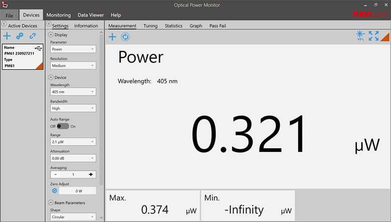
Click to Enlarge
Power Measurement Mode: Set up and configure up to eight power meters.

Click to Enlarge
Power Tuning Mode: Simulated analog needle and digital measurement value provided. Delta Mode, enabled above, shows the fluctuation range during the measurement period.
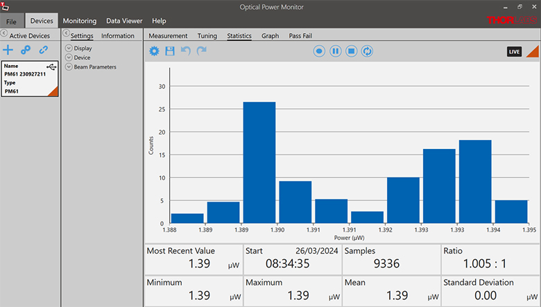
Click to Enlarge
Power Statistics Mode: Calculate numerical statistics for a pre-determined measurement period. The panel displays the analyzed values in a bar graph and the results as numerical values.
Click to Enlarge
Position Tuning Mode: Tuning mode can be used with a thermal position & power sensor to aid in beam alignment.
Click to Enlarge
Position Statistics Mode: Statistics mode also provides aggregate information for thermal position & power sensors.
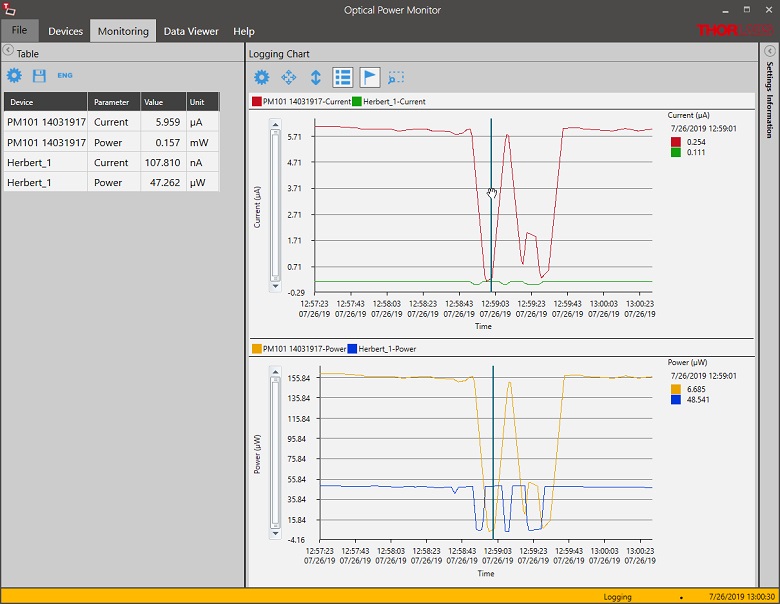
Click to Enlarge
Data Logging: Enable long-term measurement and simultaneous recording from up to eight power meters. Save data as .csv files for later processing while measurement results are displayed in a graph in real time.
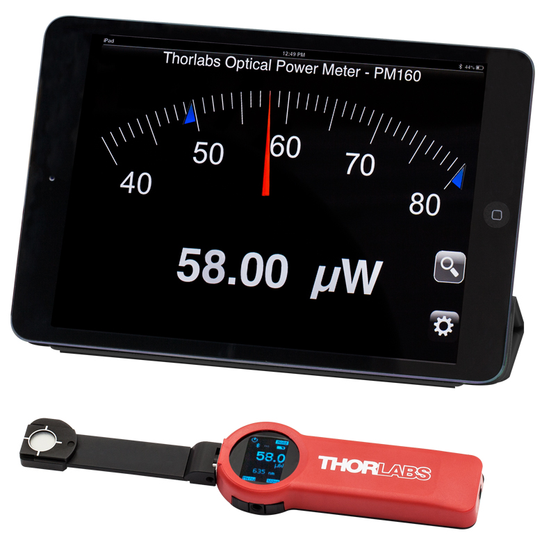
Click to Enlarge
The PM160 wireless power meter, shown here with an iPad mini (not included), can be remotely operated using Apple mobile devices.
This tab outlines the full selection of Thorlabs' power and energy sensors. Refer to the lower right table for power meter console and interface compatibility information.
In addition to the power and energy sensors listed below, Thorlabs also offers all-in-one, wireless, handheld power meters and compact USB power meter interfaces that contain either a photodiode or a thermal sensor, as well as power meter bundles that include a console, sensor head, and post mounting accessories.
Thorlabs offers four types of sensors:
- Photodiode Sensors: These sensors are designed for power measurements of monochromatic or near-monochromatic sources, as they have a wavelength dependent responsivity. These sensors deliver a current that depends on the input optical power and the wavelength. The current is fed into a transimpedance amplifier, which outputs a voltage proportional to the input current.
- Thermal Sensors: Constructed from material with a relatively flat response function across a wide range of wavelengths, these thermopile sensors are suitable for power measurements of broadband sources such as LEDs and SLDs. Thermal sensors deliver a voltage proportional to the input optical power.
- Thermal Position & Power Sensors: These sensors incorporate four thermopiles arranged as quadrants of a square. By comparing the voltage output from each quadrant, the unit calculates the beam's position.
- Pyroelectric Energy Sensors: Our pyroelectric sensors produce an output voltage through the pyroelectric effect and are suitable for measuring pulsed sources, with a repetition rate limited by the time constant of the detector. These sensors will output a peak voltage proportional to the incident pulse energy.
| Console Compatibility | ||||||||
|---|---|---|---|---|---|---|---|---|
| Console Item # | PM100A | PM100D | PM400 | PM5020 | PM101 Series |
PM102 Series |
PM103 Series |
PM100USB |
| Photodiode Power | |
|
|
|
|
- | |
|
| Thermal Power | |
|
|
|
|
|
- | |
| Thermal Position | - | - | |
|
- | |
- | - |
| Pyroelectric Energy | - | a |
a |
|
- | - | |
a |
Power and Energy Sensor Selection Guide
There are two options for comparing the specifications of our Power and Energy Sensors. The expandable table below sorts our sensors by type (e.g., photodiode, thermal, or pyroelectric) and provides key specifications.
Alternatively, the selection guide graphic further below arranges our entire selection of photodiode and thermal power sensors by wavelength (left) or optical power range (right). Each box contains the item # and specified range of the sensor. These graphs allow for easy identification of the sensor heads available for a specific wavelength or power range.
| Photodiode Power Sensors |
|---|


| Thermal Power Sensors |
|---|


| Thermal Position & Power Sensors |
|---|

| Pyroelectric Energy Sensors |
|---|


Sensor Options
(Arranged by Wavelength Range)
Sensor Options
(Arranged by Power Range)
Thorlabs offers a wide selection of power and energy meter consoles and interfaces for operating our power and energy sensors. Key specifications of all of our power meter consoles and interfaces are presented below to help you decide which device is best for your application. We also offer self-contained wireless power meters and compact USB power meters.
When used with our C-series sensors, Thorlabs' power meter consoles and interfaces recognize the type of connected sensor and measure the current or voltage as appropriate. Our C-series sensors have responsivity calibration data stored in their connectors. The console will read out the responsivity value for the user-entered wavelength and calculate a power or energy reading.
- Photodiode sensors deliver a current that depends on the input optical power and the wavelength. The current is fed into a transimpedance amplifier, which outputs a voltage proportional to the input current. The photodiode's responsivity is wavelength dependent, so the correct wavelength must be entered into the console for an accurate power reading. The console reads out the responsivity for this wavelength from the connected sensor and calculates the optical power from the measured photocurrent.
- Thermal sensors deliver a voltage proportional to the input optical power. Based on the measured sensor output voltage and the sensor's responsivity, the console will calculate the incident optical power.
- Energy sensors are based on the pyroelectric effect. They deliver a voltage peak proportional to the pulse energy. If an energy sensor is recognized, the console will use a peak voltage detector and the pulse energy will be calculated from the sensor's responsivity.
The consoles and interfaces are also capable of providing a readout of the current or voltage delivered by the sensor. Select models also feature an analog output.
Consoles
| Item # | PM100A | PM100D | PM400 | PM5020 |
|---|---|---|---|---|
| (Click Photo to Enlarge) | 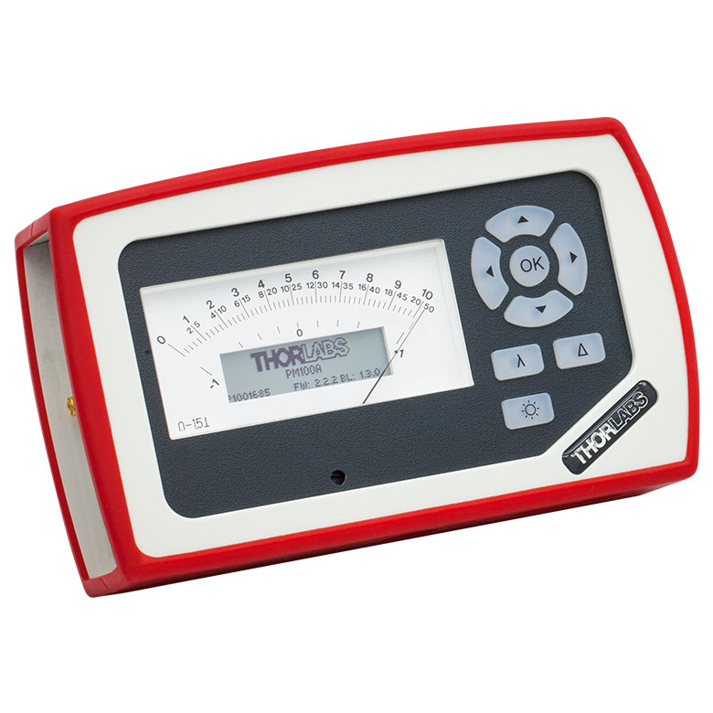 |
 |
 |
 |
| Key Features | Analog Power Measurements | Digital Power and Energy Measurements | Digital Power and Energy Measurements, Touchscreen Control | Dual Channel |
| Compatible Sensors | Photodiode and Thermal Power | Photodiode Power, Thermal Power, and Pyroelectric Energya | Photodiode Power, Thermal Power, Thermal Power and Position, and Pyroelectric Energya | Photodiode Power, Thermal Power, Thermal Power and Position, and Pyroelectric Energy |
| Housing Dimensions (H x W x D) |
7.24" x 4.29" x 1.61" (184 mm x 109 mm x 41 mm) |
7.09" x 4.13" x 1.50" (180 mm x 105 mm x 38 mm) |
5.35" x 3.78" x 1.16" (136.0 mm x 96.0 mm x 29.5 mm) |
9.97" x 4.35" x 11.56" (253.2 mm x 110.6 mm x 293.6 mm) |
| Channels | 1 | 2 | ||
| External Temperature Sensor Input (Sensor not Included) | - | - | Readout and Record Temperature Over Time | Readout and Record Temperature Over Time |
| External Humidity Sensor Input (Sensor not Included) | - | - | Readout and Record Humidity Over Time | Readout and Record Humidity Over Time |
| Input/Output Ports | - | 4 GPIO, Programmable | 4 Configurable Digital I/O Channels | |
| Shutter Control | - | - | - | Support for SH05R(/M) or SH1(/M) Optical Shutter with Interlock Input |
| Fan Control | - | - | - | |
| Source Spectral Correction | - | - | ||
| Attenuation Correction | - | - | ||
| External Trigger Input | - | - | - | |
| Display | ||||
| Type | Mechanical Needle and LCD Display with Digital Readout | 320 x 240 Pixel Backlit Graphical LCD Display | Protected Capacitive Touchscreen with Color Display | |
| Dimensions | Digital: 1.9" x 0.5" (48.2 mm x 13.2 mm) Analog: 3.54" x 1.65" (90.0 mm x 42.0 mm) |
3.17" x 2.36" (81.4 mm x 61.0 mm) |
3.7" x 2.1" (95 mm x 54 mm) |
4.32" x 2.43" (109.7 mm x 61.6 mm) |
| Refresh Rate | 20 Hz | 10 Hz (Numerical) 25 Hz (Analog Simulation) |
25 Hz | |
| Measurement Viewsb | ||||
| Numerical | ||||
| Mechanical Analog Needle | - | - | - | |
| Simulated Analog Needle | - | |||
| Bar Graph | - | |||
| Trend Graph | - | |||
| Histogram | - | - | - | |
| Statistics | ||||
| Memory | ||||
| Type | - | SD Card | NAND Flash | SD Card |
| Size | - | 2 GB | 4 GB | 8 GB |
| Power | ||||
| Battery | LiPo 3.7 V 1300 mAh | LiPo 3.7 V 2600 mAh | - | |
| External | 5 VDC via USB or Included AC Adapter | 5 VDC via USB | Line Voltage: 100 - 240 V | |


| Posted Comments: | |
Florian Fage
(posted 2024-09-03 09:17:42.247) Hi, is the PM100USB is linux compatible ? Do you provide a software ? Or if not do you provide drivers and API ?
Thank you very much! GBoedecker
(posted 2024-09-03 10:51:58.0) Thank you for your feedback! If NI VISA can be installed on your Linux system, you can use PM100USB with SCPI commands. I will also send you some Linux drivers and you can test if they are compatible with your Linux. Marco Novarese
(posted 2024-07-15 17:10:08.943) How do i access the interface (PM100USB) and so the S122C via Matlab in order to read the input power while performing sweeps? Thank you! GBoedecker
(posted 2024-07-16 07:59:03.0) Dear Marco, thank you for your feedback. You can find a Matlab example for the powermeters on the Thorlabs Github page, that shows how to read the power. Dave Walwark
(posted 2024-01-23 12:36:23.797) This is information for prospective buyers and users of the PM100USB (a note on PM101U at bottom).
The USB-query time for a power measurement alone (averaging=1) is 3.1 ms, +/- 1 ms (a 99% CI), but these durations are NOT normally distributed. Most queries are 3.1 ms by far, but ~4 ms is not uncommon (this may be from USB bus issues rather than a device shortcoming). I found the in-practice query-rate to be ~320 Hz, which is slightly better than the specified 300 Hz. However note that the first query in a group will take ~103 ms (delay from autoranging?).
During averaging (averaging > 1), the sample rate is 3 kHz. In the manual (Version 1.7) on page 26 it says each sample takes 3 ms, but this is wrong. Each averaging sample takes about 0.334 ms.
I performed this testing using the pysweepme PM100USB driver in an IDE. See sweep-me.net for free software and PM100USB driver (also K10CR1 driver) that can be used to synchronize lab equipment for experiments.
As an aside, I found that the PM100USB had better noise performance than the PM101U, when comparison of dark-levels of an S405C sensor were made. PM100USB had much smaller standard deviations in the sensor dark level, by a factor of ~20x! I returned the PM101U and got another PM100USB. hchow
(posted 2024-01-25 04:20:11.0) Dear Mr. Walwark, thank you for your valuable feedback. I will let our developers know about these issues. Bernd Kaifler
(posted 2023-09-15 19:55:23.34) I am developing a driver for the PM100USB for our measurement system application (C code base running on Linux). Is there any documentation listing the SCPI commands understood by the device? dpossin
(posted 2023-09-18 10:35:44.0) Dear Bernd,
Thank you for your feedback. The SCPI commands can be found here: C:\Program Files (x86)\IVI Foundation\VISA\WinNT\TLPM\Manual Bert Pilles
(posted 2023-09-12 13:33:13.64) der schnelle Auslesemodus des PM103 (ausgelesen in LabVIEW) scheint fehlerhaft zu sein:
1. es werden absurde Werte angezeigt (10^-34 o.ä.)
2. die Werte skalieren nicht linear mit der eingestrahlten Leistung
Bei anderen Messmodi (Sequez Messung) treten diese Probleme nicht auf GBoedecker
(posted 2023-09-13 04:36:58.0) Thank you for your feedback! I need more details to discuss your question. I will contact you directly. Hogan Pope
(posted 2023-07-17 13:29:05.2) Hello, I"m using PM100D and TLPM library in C# to build a custom software to read power. Basic functions seem to work well, but I can't find a function to read max power measured or to reset the max power measured. Is there anyway to retrieve this data?
Thanks. GBoedecker
(posted 2023-07-18 04:06:43.0) Thank you very much for you feedback! There is no method in the TLPM library that directly delivers the maximum power. You can write this method in your application, based on the method that measures the power. user
(posted 2023-06-07 00:39:38.33) Will the PM103 in combination with an S121C power meter head allow me to resolve a pulsed laser with a pulse duration of about 1ms and a repetition rate of 300 Hz ? The specs say it has a "readout rate" of 100 kS/s, so does that mean I can use the PM103 to sample my pulsed laser waveform with a timing resolution of 10 microseconds ?
Does the standard Thorlabs software allow to do this or do we need to write our own application in order to achieve such fast sampling (similar to an oscilloscope) ? wskopalik
(posted 2023-06-12 10:41:00.0) Thank you very much for your feedback!
Yes, pulses with 1 ms duration and 300 Hz repetition rate can be resolved by the PM103 and the S121C. The resolution which can be achieved with this combination is 10 µs.
The provided software has a SCOPE mode which can be used to record data with 100kS/s. This mode works similar to an oscilloscope. I will contact you directly to provide further information. Guillaume Gilson
(posted 2023-04-05 09:46:20.44) Hello :) I am using a PM101 readout device to interface and measure a custom thermopile sensor (based on TD15A detector). When connecting this custom sensor to a PM400 readout device (with screen), I don't face any issue. When I use the PM101 with Thorlabs OPM software (Windows 10) and the custom sensor, I have no issue. Now, when I try to interface the sensor with the PM101 on a RaspberryPi, using SCPI commands in Python, it doesn't work properly. More precisely, I can interface the PM101 without issue (using SCPI commands) but the readout power/voltage values are not relevant AND insensitive to the power applied to the sensor... Can you provide a command list to make sure it works in this setup?
For completion, here is the command list I use so far:
self.opm.comm.write("INIT")
sleep(0.1)
self.opm.comm.write("INP:ADAP THER")
print(self.opm.comm.ask("INP:ADAP?"))
self.opm.comm.write("CONF:SCAL:POW")
print(self.opm.comm.ask("CONF?"))
self.opm.comm.write("SENS:POW:RANG:AUTO ON")
print(self.opm.comm.ask("SENS:POW:RANG:AUTO?"))
self.opm.comm.write("SENS:AVER 10")
print(self.opm.comm.ask("SENS:AVER?"))
print(self.opm.comm.ask("SENS:POW:UNIT?"))
self.opm.comm.write("SENS:CORR:POW:THER:RESP 14E-4") #5e-4 print(self.opm.comm.ask("SENS:CORR:POW:THER:RESP?")) #5e-4
print(self.opm.comm.ask("INP:ADAP?"))
sleep(0.5)
for i in range(10):
print(self.opm.ask("MEAS:POW?"))
sleep(0.5) GBoedecker
(posted 2023-04-12 05:16:28.0) Thank you for your feedback! I would recommend to first test the command sequence on the Windows computer. I will contact you directly for further discussion. user
(posted 2023-03-28 12:47:32.987) Dear Thorlabs-Team,
are there Linux drivers for the PM101 available?
Thank you very much,
Jonas fmortaheb
(posted 2023-03-29 06:41:22.0) Thank you very much for contacting Thorlabs. I will contact you directly to provide you with further information. Chance Hanusek
(posted 2022-12-15 12:34:16.153) Not seeing a spec PDF. For most products there is a 4 page summary flyer (e.g. S120C-SpecSheet) but not PM100USB. Only seeing the manual.
Is there a SpecSheet? hchow
(posted 2022-12-16 05:20:28.0) Dear Mr. Hanusek, thank you for your feedback. Yes, you can see the specifications sheet for the PM100USB by clicking on the "Specs" tab on this webpage. Alternatively, you can also click and download the Manual for the PM100USB, and the technical specifications for this device is found on page 32. Thank you. Yun Jang
(posted 2022-07-23 16:17:22.83) Hello, I"m using PM100USB and TLPM library to build a custom software to read power. Basic functions seem to work good, but I can't find a function to read range values.
When you turn off auto-range, you can select one of the range values (maximum value of each range). Can you let me know how to retrieve those range values? It seems TLPM.h defines these ranges values for current and energy, but not power. Thanks. wskopalik
(posted 2022-07-26 05:48:59.0) Thank you very much for your feedback!
There is a function “TLPM_setPowerRange” which can be used to select the power range. As an input, you can enter the expected power of your light source and the power meter will switch to the range just above this power. The minimum and maximum power range can also be retrieved by using the function “TLPM_getPowerRange”.
I will contact you directly to provide further assistance. Samuel Eardley
(posted 2022-05-06 14:12:10.173) Hi
I am using the PM103U with a ES111C Pyroelectric Energy Sensor.
Whenever I change the measurement range the measured energy changes. For example when the range is set to 270uJ it measures a pulse as 177uJ, then if I change the range to 550uJ the measured energy jumps up to 213uJ.
Is this a known issue or do I have a faulty meter?
Which measurement should I trust? hkarpenko
(posted 2022-05-10 10:14:23.0) Dear Samuel,
thank you very much for your feedback.
The behaviour you are observing, is normal and is due to the measurement principal of the pyroelectric sensor.
I will contact you directly to discuss this further with you. user
(posted 2020-10-09 03:16:34.947) Hello, can you please provide the information how to use this power meter with Raspberry pi? wskopalik
(posted 2020-10-13 05:37:28.0) Thank you very much for your inquiry.
A Raspberry Pi usually works with a Linux-based operating system. We can provide drivers for Ubuntu for the optical power meters which might be compatible with the Raspberry Pi operating system as well. Alternatively, you can e.g. use PM101 or PM101R which have an RS232 interface which is available on the Raspberry Pi as well. So you could communicate with the power meter directly on this interface and would not need any additional drivers.
I have contacted you directly to discuss these options in more detail. X Sun
(posted 2020-07-08 12:33:29.57) I have downloaded the the power meter utility 2.2.
run the software my PM100USB doesn't appear in the device list window, rescan or unplug/plug didn't work. Though the PM100USB showed in windows Device manger with no error. MKiess
(posted 2020-07-09 05:27:04.0) This is an response from Michael of Thorlabs. Thank you very much for your inquiry. The Thorlabs Optical Power Monitor (OPM) uses the newer power meter driver TLPM.dll instead of the formerly used NI-VISA™-based driver PM100D.dll.
Although both drivers are included in the download, the new TLPM.dll driver is automatically installed with the OPM software. The driver can be changed with the tool, Driver Switcher. So if you are using the OPM software, make sure that the TLPM.dll drivers used. I have contacted you directly to discuss further details. Ekin Kocabas
(posted 2020-06-18 10:55:17.2) This is in response to the question by "Moritz Jung (posted 2020-05-28 09:26:52.493)"
I found the following functions in TLPM drivers useful for sending SCPI commands to the power meter (though I ended up not using this feature much). As MKiess mentioned, a call to TLPM_init is needed to initialize the connection first.
TLPM_writeRaw
TLPM_readRaw MKiess
(posted 2020-06-19 09:23:48.0) This is a response from Michael at Thorlabs. Thank you very much for this feedback and for completing this information. Moritz Jung
(posted 2020-05-28 09:26:52.493) Hello, I have a similar question as asked before in these comments: According to the manual, the new TLPM.dll driver can be used togehter with SCPI commands, "as long as the user establishes an USBTMC protocol". Can you give any details on how this is supposed to be done? Is it possible to use the OPM software without changing the driver?
When I switch to the old PM100D driver, the device can be accessed via NI-VISA. But I would prefer sticking to the up to date drivers.
Thanks for your answer! MKiess
(posted 2020-06-05 05:21:47.0) This is a response from Michael at Thorlabs. Thank you very much for your inquiry. You can use the OPM software with the TLPM drivers as well as communicate with the TLPM drivers via SCPI commands.
When installing the OPM software, the TLPM drivers are installed by default and are used when the software is started.
When communicating via SCPI commands and using the TLPM driver, the device must be initialized with the TLPM functions, i.e. with the function "TLPM_init".
Afterwards the driver functions can be used together with the SCPI commands for communication. Ekin Kocabas
(posted 2019-10-18 18:37:25.303) I use a S154C detector connected to PM101 and I observe the AO1 fast analog output of the power meter via an oscilloscope as I apply a square current pulse to a laser diode. With another detector/power meter combination I can see ~1 microsecond rise-time (detector limited), however, S154C + PM101 combination results in 28 ms (bandwidth high) or 38 ms (bandwith low setting) rise times. This is very different than the 100 KHz bandwidth in the PM101 specs. What is a typical rise-time that I should expect from S154C? Are there other detectors compatible with PM101 which would lead to faster rise times? If there is a special setting that I need to apply to observe KHz level signals could you let me know? Thank you. dpossin
(posted 2019-10-25 06:22:33.0) Dear Ekin,
Thank you for your feedback. As the bandwith of our powermeter are limited to a maximum value of 100kHz, we can not provide a rise time of 1µs. The behaviour you are observing is due to a firmware bug which always kept the bandwith on low status. We corrected this issue with the last firmware update which we will provide on our website ASAP. I reached out to you in order to provide further assistance. Sajjad Haidar
(posted 2019-10-03 11:02:33.577) Hello
I have been using PM101 interface with a thermal sensor.
I was wondering, do you have any Python support files for PM101?
Thanks MKiess
(posted 2019-10-10 06:02:20.0) This is a response from Michael at Thorlabs. Thank you very much for your inquiry. I contacted you directly to send you the necessary information to control the PM101 in Phython. Ekin Kocabas
(posted 2019-08-26 18:20:09.663) I had two questions on PM100USB power meters. [Q1] The latest version of the manual (ver 1.4, date 9 Aug 2019) states in Sec 7.1 that "the user can use the SCPI commands with the new TLPM.dll driver, as long as the user establishes an USBTMC protocol." Can you provide details on establishing a USBTMC connection to PM100USB, what additional piece of software do I need? [Q2] The new PM101x Write Your Own Application manual (Version: 1.0 Date: 12-Aug-2019) provides three tables that summarize status registers in Sec 3.4 for PM101 series power meters. Can you provide a similar set of tables for PM100USB? Thank you. MKiess
(posted 2019-08-29 08:34:23.0) This is a response from Michael at Thorlabs. Thank you very much for your inquiry. For USBTMC a VISA installation is necessary. NI-VISA is the most widely used, but other implementations like TekVISA are also possible.
I contacted you directly to provide further support and to send you the desired status register for the PM100USB. hartwig s
(posted 2019-07-09 08:09:16.16) Be advised when measuring DLP projectors with the PM100-USB: The auto-adjust function for the measurement range in the software specifically cannot handle DLP projectors (running ramp protocols). In general, it is better to manually set the measurement range beforehand. MKiess
(posted 2019-07-12 09:08:08.0) This is a response from Michael at Thorlabs. Thank you very much for the feedback. Depending on the wavelength of the measured light and the sensor used, it is essential to set the wavelength in the Optical Power Monitor software to compensate the measurement result for the wavelength-dependent sensitivity of the sensor.
Therefore, when measuring DLP projectors, it is a good solution to adjust the settings manually. In general, it is recommended to use the default Auto Range ON setting.
Auto Range OFF allows you to set the measurement range manually, which is recommended for measuring pulsed light sources, for example. anish.goel
(posted 2019-03-04 13:19:21.693) Hi, I am interfacing the TLPM in C# but unable to find any documentation regarding the functions (specifically "return values from functions" for example int setwavelength: What will it return. What will it mean)
Where do I find proper documentation for the SDK ? swick
(posted 2019-03-08 03:23:38.0) This is a response from Sebastian at Thorlabs. Thank you for the inquiry.
After installing the software package you can find documentation about the functions at path:
C:\Program Files (x86)\IVI Foundation\VISA\WinNT\TLPM\Manual kocabass
(posted 2019-02-19 16:45:38.96) Hello,
When I use the TLPM library drivers wrapped in python via ctypes, I see that I get different measurement results if I issue a 1 sec wait time between TLPM_setWavelength and TLPM_measPower vs the case when there is no wait time. It seems like the TLPM_setWavelength function call takes some time to finalize but it returns back to the enclosing program before then. I tried to look into various device registers to determine when setWavelength operation ends but could not find the right register location for that. I'd appreciate any comments on how I can make sure that the TLPM_setWavelength calls have done what they are supposed to do, without having to issue wait commands in between wavelength change and measure commands. nreusch
(posted 2019-02-26 06:42:59.0) This is a response from Nicola at Thorlabs. Thank you very much for the inquiry. You could probably add a loop to your program using the TLPM_getWavelength command to check whether set and get wavelength match before the program actually performs a measurement. I will contact you directly for further assistance. ericshaner8d
(posted 2018-12-26 09:24:11.07) The description under 'software' for the PM100USB says 'visual basic' examples are included with the driver. They are not, just C and C# are included. nreusch
(posted 2019-01-03 07:26:25.0) This is a response from Nicola at Thorlabs. Thank you for the note. You are right about the fact that Visual Basic examples are not installed with software and drivers. We will correct the statement on our website. segreto
(posted 2018-11-05 10:01:26.68) I have developed my own driver to read data at high speed from the PM100USB and found that the performance of this device is severely limited by the lack of the SCPI command "DATA:FORMAT {FLOAT, ASCII}" that would allow the user to choose to transfer data directly in binary format, thus saving the time required for the (in most of the cases totally useless) binary to ASCII conversion.
Do you plan to implement this command in the near future? swick
(posted 2018-11-21 03:27:17.0) This is a response from Sebastian at Thorlabs. Thank you for sharing your findings with us. We will look into this.
At the time we do not plan to change the SCPI command set. juozas
(posted 2018-10-24 13:02:44.853) Hello,
We're writing custom software that we need to work on multiple operating systems, including Linux and macOS. Are there still no drivers or other tools that would enable development for those operating systems? If writing our own drivers is the only option, where could we get complete documentation?
Thank you! swick
(posted 2018-11-21 04:20:12.0) This is a response from Sebastian at Thorlabs. Thank you for the inquiry.
For Linux we can provide shared objects but for macOS we do not provide drivers at the moment.
I contacted you directly to get further information about the operating systems you work with. ebull
(posted 2018-08-20 11:08:37.53) We use PM100USB and PM100D frequently for measurements with Thorlabs sensors and for measurements with our own photodiodes - the ability to use a custom sensor is very useful to us. We often do not need the screen of the PM100D, but we generally want the analog output that the PM100USB lacks.
A PM100USB with analog output would be the perfect device for many of our uses.
Elias nreusch
(posted 2018-08-23 05:45:12.0) This is a response from Nicola at Thorlabs. Thank you for your suggestion. We are already working on the realization of such a device. I will contact you directly with further information. stefano.valle
(posted 2018-07-31 15:51:34.8) It would be really useful to have a library for Matlab, or at least a set of command line to be able to control to set the power meter and retrieve the data required, without passing through Labview or C++ swick
(posted 2018-08-08 04:36:30.0) This is a response from Sebastian at Thorlabs. Thank you for the feedback.
After establishing the USB connection SCPI commands could be used for remote control. I contacted you directly to provide a list of these commands. jim.mcginnis
(posted 2018-06-06 07:57:31.237) Sent email to tech support regarding the issues below. jim.mcginnis
(posted 2018-06-05 15:44:28.107) Followup:
Windows version is Windows 10, 1803 Creators Spring Update. Reinstalled all drivers from Thorlabs.
Thanks jim.mcginnis
(posted 2018-06-05 15:37:13.973) We have constructed both 32bit and 64bit applications for reading an optical sensor connected to the PM100USB. The applications work correctly on Windows 7.
Building 64 bit C# application that combines the Kinesis 64 bit motion control libraries with the TLPM 64 bit libraries in a single application. Works as expected on Windows 7
Problem arises when building and running on Windows 10. The TLPM calls to get resources returns more than just the PM100USB devices. Selecting the correct device returned by the get resource call and trying to configure the device results in exception thrown by the TLPM call.
This does not happen on the Windows 7 platform. Only Windows 10.
Is this a known problem for the 64 bit TLPM libraries??
We have no issues with the Kinesis 64 bit libraries on Windows 10 or 7.
Suggestions??? jacyjacythomson
(posted 2017-04-24 16:15:16.97) Hi I am trying to develop a small program in LabVIEW like the PM100D Simple Example.
I need the Commands to send to the instrument.
These are similar to :
SENS:AVER
There should be a Programming Command Manual or a link on your website.
Thank you, Jeff swick
(posted 2017-04-26 04:52:50.0) This is a response from Sebastian at Thorlabs. Thank you for the inquiry.
An overview of SCPI commands for our Power Meter Consoles can be found in the manual at chapter "SCPI Commands".
I will contact you directly for further assistance. asmirnov
(posted 2017-02-02 01:10:38.227) We use a number PM100USB interfaces. If two PM100USB connected simultaneously, some of them (about 15% of all) can hang up. It doesn`t depend on NI-VISA RTE/driver/firmware version, MotherBoard model etc. Is it a fabric or software defect? swick
(posted 2017-02-03 05:41:03.0) This is a response from Sebastian at Thorlabs. Thank you for the feedback.
Using more than one PM100USB simultaneously at one operating system should work without problems.
The Power Meter Consoles are based on SCPI commands, which avoids driver conflicts in the operating system.
A known issue which avoids using multiple devices at the same time could be USB-Hubs, bad quality USB cables and/or a slow PC.
I will contact you directly for assistance and troubleshooting. ddeng
(posted 2017-01-31 19:34:13.383) Could you support this PM100USB under Windows 10? I have one unit. wskopalik
(posted 2017-02-01 03:22:18.0) This is a response from Wolfgang at Thorlabs. Thank you very much for your inquiry.
You can use the software provided on the website to operate the PM100USB. Supported operating systems are Windows® XP (32 bit) SP3 or Windows® Vista, 7, 8.1, or 10 (32 bit, 64 bit).
I will contact you directly to provide further assistance. ester0904bond
(posted 2016-03-28 09:22:41.837) Can this modal do data sampling up to 100kHz?
if can, can we do that in labview?
thank you besembeson
(posted 2016-03-28 09:49:18.0) Response from Bweh at Thorlabs USA: This may not be possible, even with a photodiode sensor though we have a 16 bit AD converter in the PM100USB. Speed loss could come from the queries of commands which always checks the availability/status of the sensor. You could write your own routines which allows for faster sampling rates but the USB 2.0 port will limit this and the PM100USB has no analog output to bypass this. You may consider instead the PM100D, PM100A or the PM200. roger_york
(posted 2016-03-11 19:01:25.26) Is there anyway to interface the PM100USB with a MacBook Air? shallwig
(posted 2016-03-14 11:53:36.0) This is a response from Stefan at Thorlabs. Thank you very much for your inquiry. At the moment we have unfortunately no drivers available to run our power meter software with Apple OS. nherrick
(posted 2015-10-22 16:40:57.477) What do you think are the chances of being able to use the PM100USB with a raspberry pi? tschalk
(posted 2015-10-23 07:11:50.0) This is a response from Wolfgang at Thorlabs. Thank you for your inquiry. A Raspberry Pi usually works with a Linux-based operating system for which we unfortunately can't offer full support. There is however some information about the use of our powermeters in Linux and I will contact you directly about it. johnhobbs
(posted 2015-09-30 13:34:26.513) Please fix your labview drivers for the PM100USB! I just upgraded to Labview 2015 and your labview drivers now hang up. I can send my labview driver if you want for the PM100USB. bottom line you cannot ini the PM100USB read the power and then close the device multiple times without it hanging up. I think your drives are not properly closing the resources for the device.
best,
John Hobbs shallwig
(posted 2015-10-01 09:55:41.0) This is a response from Stefan at Thorlabs. Thank you very much for your inquiry. We checked the drivers with Labview 2015 and could not reproduce this problem. I will contact you directly to troubleshoot this in more detail. bo.jing
(posted 2015-05-26 17:42:20.707) The inner plastic (grey) USB connector on the PCB board inside the device detached itself at the soldering points. Can I send this unit back for repairs? We are quite disappointed at this obvious point of failure. shallwig
(posted 2015-05-27 06:33:02.0) This is a response from Stefan at Thorlabs. Thank you very much for contacting us in this matter. We are really sorry for the inconveniences you had through this. I will contact you directly to handle the repair/exchange as soon as possible. a.andreski
(posted 2015-05-12 17:41:44.017) Is there a way to read out a time-series of datapoints (lets say 1M samples) using your C-series photodioide sensors with a PM100USB but with a specific sampling rate? tschalk
(posted 2015-05-13 07:02:08.0) This is a response from Thomas at Thorlabs. Thank you very much for your feedback. The maximum achievable sampling rate is about 300Hz. The GUI provides a function called fast logging which enables the maximum logging frequency of the unit. If you want to sample a signal in the MHz range you could use one of our amplified photodetectors in combination with a scope. I will contact you directly to discuss your application. catox
(posted 2014-07-23 15:14:35.38) It would be great if you could offer a similar product with Serial via USB interface to remove the requirement for NI-VISA installation. shallwig
(posted 2014-07-23 09:52:01.0) This is a response from Stefan at Thorlabs. Thank you very much for your feedback. At the moment it is not planned to offer the PM100USB in such a configuration. But the PM160 http://www.thorlabs.com/newgrouppage9.cfm?objectgroup_id=7233&pn=PM160#7267 allows you to communicate with your PC without using VISA as it can additionally to USB also transmit data by Bluetooth. I will contact you directly to discuss your application in detail. bagresci
(posted 2014-04-17 17:10:32.223) I found a method to communicate with pm100usb. I and using Agilient USBTMC kernel driver with Scientific linux 6.4. (http://www.home.agilent.com/upload/cmc_upload/All/usbtmc.html?&cc=KR&lc=kor). Below is my shell script :
./usbtmc_ioctl 1 reset
./usbtmc_ioctl 1 clear
echo INIT > /dev/usbtmc1
while((i<100))
do
./usbtmc_ioctl 1 reset
./usbtmc_ioctl 1 clear
echo READ? > /dev/usbtmc1
cat /dev/usbtmc1
((i=i+1))
done
./usbtmc_ioctl 1 reset
./usbtmc_ioctl 1 clear
echo ABOR > /dev/usbtmc1
./usbtmc_ioctl 1 reset
./usbtmc_ioctl 1 clear shallwig
(posted 2014-04-17 08:49:33.0) This is a response from Stefan at Thorlabs. Thank you very much for your feedback and sharing this helpful information with us. I will contact you directly to discuss any open questions you have in this matter. hadmack
(posted 2013-07-08 17:48:23.577) Could you please provide an update on the compatibility of PM100USB with the Linux USBTMC driver? tschalk
(posted 2013-07-10 08:40:00.0) This is a Response from Thomas at Thorlabs. Thank you very much for your inquiry. To control the device with Linux you would need a USBTMC-driver for Linux and the instrument-driver-code for the corresponding SCPI commands to communicate via the USBTMC driver. The low level specifications are the followings: - Universal Serial Bus Test and Measurement Class Specification (USBTMC) Revision 1.0. USB Implementers Forum. April 14, 2003 - and - Universal Serial Bus Test and Measurement Class, Subclass USB488 Specification (USBTMC-USB488) Revision 1.0. April 14, 2003 - and the command structures are - IEEE Std 488.2-1992; IEEE Standard Codes, Formats, Protocols, and Common Commands For Use With IEEE Std 488.1-1987, IEE Standard Digital Interface for Programmable Instrumentation - and the used command format is - Standard Commands For Programmable Instruments (SCPI) -. You can use the source code of our instrument driver which is an open source code under LGPL. This one can be changed so that it is possible to use the Linux - USBTMC communication instead of the NI functions. I will contact you directly for more detailed information. jvigroux
(posted 2012-06-20 09:54:00.0) A response from Julien at Thorlabs: Thank you for your feedback! The communication of the PM100USB is based on the USBTMC protocol. We rely on the VISA engine to create a stable overlayer on the USBTMC but if one does not want to use the VISA engine, it is of course possible to address the USB port directly at a USBTMC level. I will contact you to discuss further the possible approaches for the driver implementation you plan. gnishi
(posted 2012-06-19 20:45:33.0) It would be great to provide the Linux driver or low level USB specification to write the driver. We don't need NI plat form, which consumes huge resources (incl. cost.), to drive this powermeter. jjurado
(posted 2011-04-06 16:35:00.0) Response from Javier at Thorlabs to last poster: Thank you very much for your feedback. I will share your comments with our design engineers for the PM100USB. Please check back with us at techsupport@thorlabs.com if you would like to check on the status of this project. user
(posted 2011-04-06 18:40:07.0) It would be great to have a product like this compatible with Android, and be able to use on a tablet or smartphone. jjurado
(posted 2011-02-14 18:14:00.0) Response from Javier at Thorlabs to huw.major: Thank you for submitting your inquiry. The crashing is most likely due to an older firmware version of the PM100USB power meter. You can upgrade to version 1.3 by installing the Device Firmware Upgrade wizard and following the instructions. You can download the firmware application via the following link:
http://www.thorlabs.com/software_pages/ViewSoftwarePage.cfm?Code=PM100x
I will follow up with you directly. huw.major
(posted 2011-02-14 11:37:25.0) Hi, I have 3 of these products and am trying to use them for prolonged testing purposes, > 1000Hrs constant use. I find them very easy to set up and use, but I have found that they constantly crash. I am using a Labview 2009 program, based on your supplied Labview example code, which seems to work fine most of the time. However, I am getting sporadic crashed of 1 or more power meters which require a power down to fix. The code is running under Windows 7, do you know of any issues with this combination? huw.major
(posted 2011-02-14 11:32:47.0) Hi I have 3 of these products and am trying to use them for prolonged testing purposes, >1000Hrs constant use. I find them very easy to set up and use, but, I have found that they constantly crash. I am using a Labview 2009 program based on your supplied Labview code which seems to work fine most of the time. However, I am getting sporadic crashes of 1 or more power meters which require a power down to fix. The code is running under Windows 7, do you know of any problems with this combination? julien
(posted 2011-01-28 11:41:52.0) a response from Julien at Thorlabs: Thank you for your feedback. Several PM100USBs can be connected to the same hub. We actually provide a small utility software that allows to readout up to 8 PM100USB simultaneously. This utility can be downloaded from the software page of the PM100USB. Concerning the Iphone compatibility, the PM100USB software is entirely NI VISA based, which is as of now unfortunately not compatible with Iphones yet. mobrien
(posted 2011-01-27 12:46:16.0) I was wondering if you have given any thought to making a PM100USB App for the iPhone etc. Our company currently does not provide smartphones or tablets to its employees but you can kind of see where things are heading...
On a related topic, we have one of these, could I connect multiple PM100USBs to a single USB port via a USB hub?
Mike |

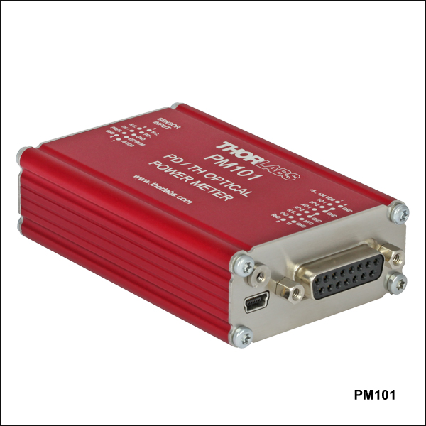 Zoom
Zoom| Power Meter Interface Quick Comparisona | ||||
|---|---|---|---|---|
| Item # | PM101 | PM101A | PM101R | PM101U |
| Photo (Click to Enlarge) | |
|
|
|
| Connectors | Mini USB & DA-15 |
Mini USB & SMA |
Mini USB & DE-9 |
Mini USB |
| Control / Digital Output | USB 2.0, RS232, or UART | USB 2.0 | USB 2.0 or RS232 | USB 2.0 |
| Analog Output | Yes | Yes | No | No |
- Compatible with Over 25 Photodiode and Thermal Power Sensors
- All Models Feature USB 2.0 Operation
- Select Models with:
- UART or RS232 Operation
- Analog Output
- Power Supply via USB (All Models) or DA-15 Connector (PM101 Only)
- Includes Certificate of Calibration
The PM101 Series Interfaces are compatible with all our C-Series photodiode and thermal power sensors. Our standard photodiode, slim photodiode, integrating sphere, and fiber sensors can collectively measure optical powers from 100 pW to 20 W. Our thermal power sensors measure optical powers from 10 µW to 200 W. Alternatively, unamplified anode- or cathode-grounded photodiodes with up to 5 mA photocurrent and thermal elements with a maximum output voltage of 1 V can be used. While all of the interfaces can be operated and powered with a PC via the mini-USB port, select interfaces have additional features such as UART or RS232 operation and analog output (see the table to the right). Models with analog output can be operated autonomously when connected to a power supply, without the need for an additional control device. All of the interfaces include reset buttons, allowing the systems to be easily rebooted.
The non-volatile memory in each interface retains the user's wavelength setting, sensitivity range, and output configuration upon shutting down or rebooting the unit, suitable for repeat measurements over a long period of time. A fast readout rate of 1000 samples per second allows active signal monitoring while the interface is in use. For precise measurements with thermal power sensors, these interfaces use nine voltage measurement ranges from 2 mV to 1 V, compared to only four ranges used by the PM100USB (see the Specs tab).
Please note that sensors are not included with these power meter interfaces. For information about our compatible sensors, please see the sensor descriptions below. Thorlabs offers a recalibration service for these interfaces, which can be ordered below (see Item # CAL-PM1). Alternatively, if you have a corresponding sensor that requires recalibration, you can include the power meter interface with the sensor for recalibration at no additional cost.
Also, we offer the USB-ABL-60 cable as a replacement for the USB cable included with each sensor; this cable includes an M2.5 locking screw to prevent accidental disconnects. Additionally, The CABRU15 USB Type-A to Serial Flying Leads Adapter (sold below) can be used to connect the RS232 serial pin outputs of the DA-15 connector on the PM101 interface and the DE-9 connector on the PM101R interface to USB for PC connection (Note: Item # PM101R cannot be powered through the DE-9 connector).

 Zoom
Zoom| Power Meter Interface Quick Comparisona | |||
|---|---|---|---|
| Item # | PM102 | PM102A | PM102U |
| Photo (Click to Enlarge) |
|
|
|
| Connectors | Mini USB & DA-15 |
Mini USB & SMA |
Mini USB |
| Control / Digital Output |
USB 2.0, RS232, or UART |
USB 2.0 | USB 2.0 |
| Analog Output | Yes | Yes | No |
- Compatible with Over 10 Thermal Power and Thermal Position & Power Sensors
- All Models Feature USB 2.0 Operation
- Select Models with:
- UART or RS232 Operation
- Analog Output
- Power Supply via USB (All Models) or DA-15 Connector (PM102 Only)
- Includes Certificate of Calibration
The PM102 Series Interfaces are compatible with all our C-Series thermal power and thermal position & power sensors. Our thermal power sensors measure optical powers from 10 µW to 200 W. Our thermal position & power sensors can concurrently measure beam position and optical powers from 0.5 mW to 50 W. Alternatively, thermal elements with a maximum output voltage of 1 V can be used. While all of the interfaces can be operated and powered with a PC via the mini-USB port, select interfaces have additional features such as UART or RS232 operation and analog output (see the table to the right). Models with analog output can be operated autonomously when connected to a power supply, without the need for an additional control device. All of the interfaces include reset buttons, allowing the systems to be easily rebooted.
The non-volatile memory in each interface retains the user's wavelength setting, sensitivity range, and output configuration upon shutting down or rebooting the unit, suitable for repeat measurements over a long period of time. A fast readout rate of 1000 samples per second allows active signal monitoring while the interface is in use. For precise measurements with thermal power sensors, these interfaces use nine voltage measurement ranges from 2 mV to 1 V, compared to only four ranges used by the PM100USB (see the Specs tab).
Please note that sensors are not included with these power meter interfaces. For information about our compatible sensors, please see the sensor descriptions below. Thorlabs offers a recalibration service for these interfaces, which can be ordered below (see Item # CAL-PM1). Alternatively, if you have a corresponding sensor that requires recalibration, you can include the power meter interface with the sensor for recalibration at no additional cost.
Also, we offer the USB-ABL-60 cable as a replacement for the USB cable included with each sensor; this cable includes an M2.5 locking screw to prevent accidental disconnects. Additionally, The CABRU15 USB Type-A to Serial Flying Leads Adapter (sold below) can be used to connect the RS232 serial pin outputs of the DA-15 connector on the PM102 interface to USB for PC connection.

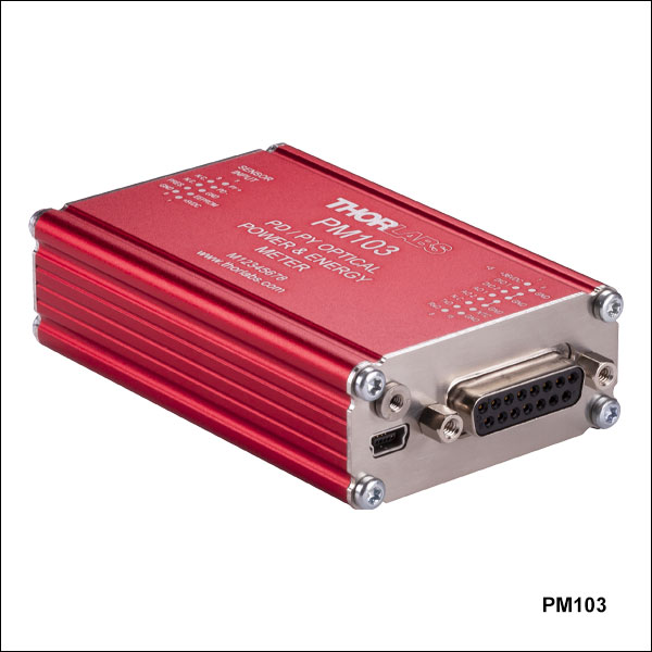 Zoom
Zoom| Power Meter Interface Quick Comparisona | ||||
|---|---|---|---|---|
| Item # | PM103 | PM103A | PM103E | PM103U |
| Photo (Click to Enlarge) |
|
|
|
|
| Connectors | Mini USB & DA-15 |
Mini USB & SMA |
Ethernet (RJ45) & DMC 0,5/7 | Mini USB |
| Power Supply Connectors | USB or DA-15 | USB | Ethernet or DMC 0,5/7 | USB |
| Control / Digital Output |
USB 2.0, RS232, or UART |
USB 2.0 | Ethernet, RS232 | USB 2.0 |
| Analog Output | Yes | Yes | Yes | No |
- Compatible with Over 20 Photodiode Power and Pyroelectric Energy Sensors
- All Models (Except Item # PM103E) Feature USB 2.0 Operation
- Select Models with:
- UART or RS232 Operation
- Analog Output
- Ethernet Operation
- Power Supply via:
- USB (All Except Item # PM103E),
- DA-15 Connector
(Item # PM103 Only) , - Ethernet or DMC 0,5/7 Connector (Item # PM103E Only)
- Includes Certificate of Calibration
The PM103 Series Interfaces are compatible with all our C-Series photodiode power and pyroelectric energy sensors. Our standard photodiode, slim photodiode, integrating sphere, and fiber sensors can collectively measure optical powers from 100 pW to 20 W. Alternatively, unamplified anode- or cathode-grounded photodiodes with currents up to 10 mA can be used. Our pyroelectric energy sensors can measure energies from 10 µJ to 15 J. Other energy sensors with voltage outputs from 20 mV to 200 V can also be used. While all of the interfaces (except Item # PM103E) can be operated and powered with a PC via the mini-USB port, select interfaces have additional features such as UART or RS232 operation and analog output (see the table to the right).
The PM103E interface can be operated by PC and powered via ethernet connection as long as your network provides power over ethernet (PoE). If power over ethernet is not provided, a 5 - 36 VDC source must be connected to pin 1 and pin 2 (ground) of the DMC 0,5/7 connector to power the device. See the Connectors tab for details. Furthermore, the DMC 0,5/7 connector provides RS232 connections to operate the device via serial interface.
Models with analog output can be operated autonomously when connected to a power supply, without the need for an additional control device. All of the interfaces include reset buttons, allowing the systems to be easily rebooted.
The non-volatile memory in each interface retains the user's wavelength setting, sensitivity range, and output configuration upon shutting down or rebooting the unit, suitable for repeat measurements over a long period of time. A fast readout rate of 100 kS/s allows active signal monitoring while the interface is in use. For precise measurements, these interfaces use thirteen voltage measurement ranges from 20 mV to 200 V and 21 current measurement ranges from 2 nA to 10 mA, compared to only four voltage and six current ranges used by the PM100USB (see the Specs tab).
The PM103 and PM103E interfaces have two configurable general purpose digital ports, DIO1 and DIO2 (see Connectors tab for details). Similarly, the PM103A has one auxiliary digital port, DIO1, with an SMA connector. The DIO1 ports can be configured as trigger input or output when reading the data in the 100 kS/s mode. DIO2 can also be configured as a pass/fail flag and queried per remote control command.
Please note that sensors are not included with these power meter interfaces. For information about our compatible sensors, please see the sensor descriptions below. Thorlabs offers a recalibration service for these interfaces, which can be ordered below (see Item # CAL-PM1). Alternatively, if you have a corresponding sensor that requires recalibration, you can include the power meter interface with the sensor for recalibration at no additional cost.
Also, we offer the USB-ABL-60 cable as a replacement for the USB cable included with each sensor (except Item # PM103E); this cable includes an M2.5 locking screw to prevent accidental disconnects. The PM103E interface includes a 1.5 m ethernet RJ45 patch cable. The CABRU15 USB Type-A to Serial Flying Leads Adapter (sold below) can be used to connect the RS232 serial pin outputs of the DA-15 connector on the PM103 interface and the DMC 0,5/7 connector on the PM103E interface to USB for PC connection. Additionally, the PM103 and PM103E devices can be powered through the CABRU15 USB adapter.

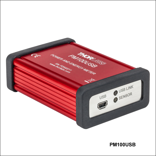 Zoom
Zoom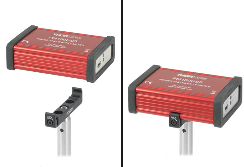
Click for Details
PM100USB Mounted to Post with ECM225 Clamp
- Compatible with Over 30 Photodiode, Thermal, and Pyroelectric Sensors
- Controlled and Powered via USB
- Includes Certificate of Calibration
The PM100USB Power and Energy Meter Interface is compatible with all our C-Series photodiode, thermal, and pyroelectric sensors except for the ES408C Fast Pyroelectric Sensor. Our C-Type standard photodiode, slim photodiode, integrating sphere, and fiber sensors can collectively measure optical powers from 100 pW to 20 W. Our thermal power sensors measure optical powers from 10 µW to 200 W. Compatible C-Series pyroelectric energy sensors can measure energies from 10 µJ to 15 J and repetition rates up to 2 kHz. Note that the ES408C sensor for repetition rates up to 10 kHz, also available below, is not recommended for use with the PM100USB interface, which supports a maximum repetition rate of 3 kHz. Alternatively, other unamplified anode- or cathode-grounded photodiodes with up to 5 mA photocurrent, thermal elements with a maximum output voltage of 1 V, or energy sensors with voltage outputs from 100 mV to 100 V may be used.
This interface can be operated and powered by a PC via the mini-USB port. A readout rate of 300 samples per second allows active signal monitoring while the interface is in use.
Please note that sensors are not included with the PM100USB. For information about our compatible sensors, please see the sensor descriptions below. Thorlabs offers a recalibration service for the PM100USB, which can be ordered below (see Item #CAL-PM1). Alternatively, if you have a corresponding sensor that requires recalibration, you can include the PM100USB with the sensor for recalibration at no additional cost.

 Zoom
Zoom
- USB 2.0 Type-A Serial Converter to Four Color Coded Ø1.05 mm Ferrules
- Connect Device RS232 Output Signals to PC
- 1.5 m Cable Length
Thorlabs' CABRU15 USB A to Serial Flying Leads Adapter Cable can be used to connect the RS232 signal output pins of Thorlabs' devices (such as the Power Meter Interfaces and Consoles) to PC. See the Connectors tab for RS232 pin assignments to compatible devices. The connector features embedded USB to TTL serial and RS232 level converter electronics for Windows, MAC, and Linux operating systems.
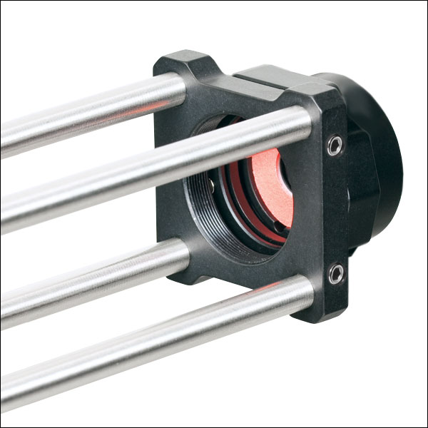
Click to Enlarge
S120C and CP44F Quick-Release Mount
- For General Purpose Optical Power Measurements
- Integrated Viewing Target for Easy Sensor Alignment
- Ø9.5 mm Sensor Aperture
- Sensor, Protective Cap, IR Target, and Thread Adapter Included
- Fiber Adapters Available Separately (See Table Below)
- See the Full Web Presentation for More Information
These Standard Photodiode Power Sensors are ideal for metering low power coherent and incoherent sources from the UV to the NIR. Each NIST-Traceable, calibrated sensor features an integrated viewing target for easy alignment, enhanced shielding against electromagnetic interference, an over-temperature-alert device, and a large Ø9.5 mm sensor aperture. The sensors are compatible with 30 mm cage systems, Ø1/2" posts, and SM1 (1.035"-40) lens tubes, and are ideal for free-space and fiber-coupled sources.
Thorlabs offers a recalibration service for these photodiode power sensors, which can be ordered below (see Item # CAL-UVPD for UV-extended Si sensors, Item # CAL-PD for Si sensors and Item # CAL-IRPD for Ge sensors).
| Item #a | S120VC | S120C | S121C | S122Ch |
|---|---|---|---|---|
| Sensor Image (Click the Image to Enlarge) |
|
|
|
|
| Aperture Size | Ø9.5 mm | |||
| Wavelength Range | 200 - 1100 nm | 400 - 1100 nm | 400 - 1100 nm | 700 - 1800 nm |
| Power Range | 50 nW - 50 mW | 500 nW - 500 mW | 50 nW - 40 mW | |
| Detector Type | Si Photodiode (UV Extended) | Si Photodiode | Ge Photodiode | |
| Linearity | ±0.5% | |||
| Resolutionb | 1 nW | 10 nW | 2 nW | |
| Measurement Uncertaintyc | ±3% (440 - 980 nm) ±5% (280 - 439 nm) ±7% (200 - 279 nm, 981 - 1100 nm) |
±3% (440 - 980 nm) ±5% (400 - 439 nm) ±7% (981 - 1100 nm) |
±5% | |
| Responsivityd (Click for Plot) |  Raw Data |
 Raw Data |
 Raw Data |
 Raw Data |
| Coating/Diffuser | Reflective ND (OD1.5)e | Reflective ND (OD1)f | Reflective ND (OD2)g | Absorptive ND (Schott NG9) |
| Head Temperature Measurement | NTC Thermistor 4.7 kΩ | |||
| Housing Dimensions | Ø30.5 mm x 12.7 mm | |||
| Cable Length | 1.5 m | |||
| Post Mountinge,f,g | Universal 8-32 / M4 Tap, Post Not Included | |||
| Aperture Thread | External SM1 (1.035"-40) | |||
| Compatible Fiber Adapters | S120-FC2, S120-FC, S120-APC2, S120-APC, S120-SMA, S120-ST, S120-LC, and S120-SC (Not Included) | |||
| Compatible Consoles | PM400, PM100D, PM100A, and PM5020 | |||
| Compatible Interfaces | PM101, PM101A, PM101R, PM101U, PM103, PM103A, PM103E, PM103U, and PM100USB | |||
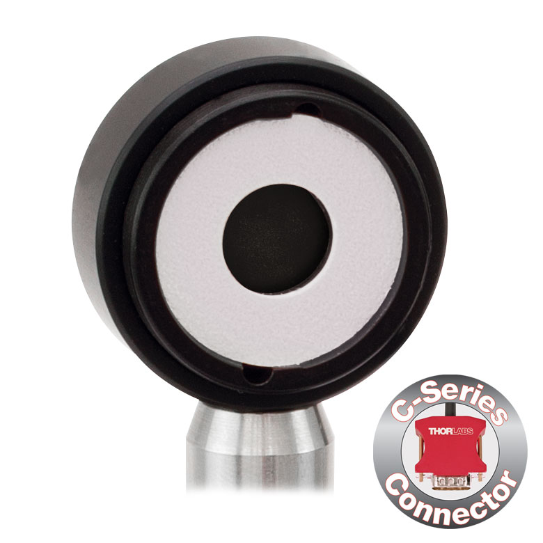

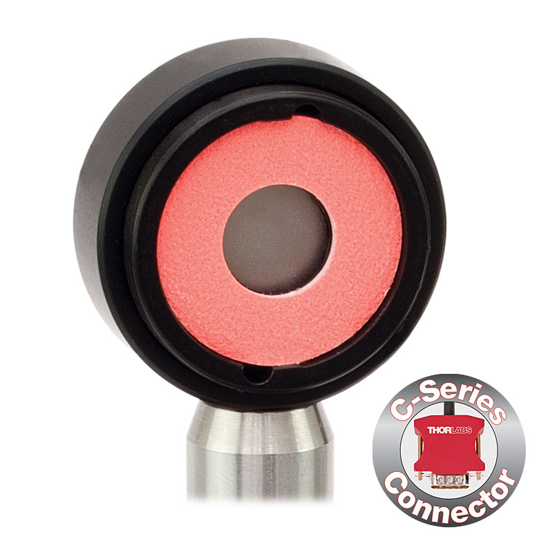
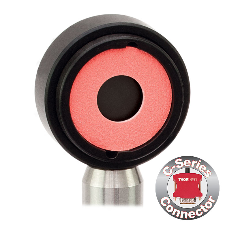

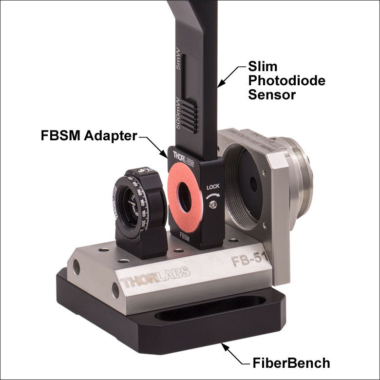
Click for Details S130C Photodiode Sensor Mounted in FiberBench System Using FBSM Mount
- For Optical Power Measurements in Confined Spaces
- Very Slim Design: 5 mm Thin on Sensor Side
- Ø9.5 mm Sensor Aperture
- Slideable ND Filter Automatically Changes Sensor Power Range
- Optional SM1A29 Adapter with VIS/IR Target and External SM1 Threading (More Details)
- Optional FBSM Mount with VIS/IR Target for FiberBench Systems (More Details)
- See the Full Web Presentation for More Information
These Slim Photodiode Power Sensors are designed to take optical source power measurements in locations where space and accessibility are at a premium. The 5 mm thin sensor end can fit between closely spaced optics, cage systems, and other arrangements where standard power meters may not fit. The NIST-Traceable, calibrated sensors also feature a large Ø9.5 mm sensor aperture and slideable neutral density filter for dual power ranges in one compact device.
A separately available SM1A29 adapter can be attached by 2 setscrews to any S130 series power sensor to mount fiber adapters, light shields, filters or any other SM1-threaded (1.035"-40) mechanics or optics. The FBSM Mount allows our S130 series power sensors to be mounted vertically into FiberBench systems for stable mounting with a minimal footprint.
Thorlabs offers a recalibration service for these photodiode power sensors, which can be ordered below (see Item # CAL-UVPD2 for UV-extended Si sensors, Item #CAL-PD2 for Si sensors, and Item # CAL-IRPD2 for Ge sensors).
| Item #a | S130VC | S130C | S132C | |
|---|---|---|---|---|
| Sensor Image (Click the Image to Enlarge) |
|
|
|
|
| Aperture Size | Ø9.5 mm | |||
| Wavelength Range | 200 - 1100 nm | 400 - 1100 nm | 700 - 1800 nmb | |
| Power Range (with Filter) |
500 pW - 0.5 mWc (Up to 50 mW)c |
500 pW - 5 mW (Up to 500 mW) |
5 nW - 5 mW (Up to 500 mW) |
|
| Detector Type | Si Photodiode (UV Extended) | Si Photodiode | Ge Photodiode | |
| Linearity | ±0.5% | |||
| Resolution | 100 pWd | 1 nWe | ||
| Measurement Uncertaintyf | ±3% (440 - 980 nm) ±5% (280 - 439 nm) ±7% (200 - 279 nm, 981 - 1100 nm) |
±3% (440 - 980 nm) ±5% (400 - 439 nm) ±7% (981 - 1100 nm) |
±5% | |
| Responsivityg (Click for Plot) | Raw Data |
Raw Data |
Raw Data |
|
| Coating/Diffuser | Reflective ND (OD1.5)c | Reflective ND (OD2)h | Absorptive ND (Schott NG9/KG3)b | |
| Housing Dimensions | 150 mm x 19 mm x 10 mm; 5 mm Thickness on Sensor Side | |||
| Cable Length | 1.5 m | |||
| Post Mounting | 8-32 and M4 Taps | |||
| Adapters (Not Included) | SM1A29: Add SM1 Thread and Viewing Target to Aperture Fiber Adapters Compatible with SM1A29 Adapter: S120-FC2, S120-FC, S120-APC2, S120-APC, S120-SMA, S120-ST, S120-SC, and S120-LC FBSM: Integrate Sensor into FiberBench Setups |
|||
| Compatible Consoles | PM400, PM100D, PM100USB, PM100A, and PM5020 | |||
| Compatible Interfaces | PM101, PM101A, PM101R, PM101U, PM103, PM103A, PM103E, PM103U, and PM100USB | |||
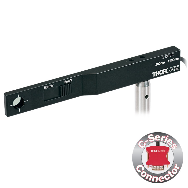
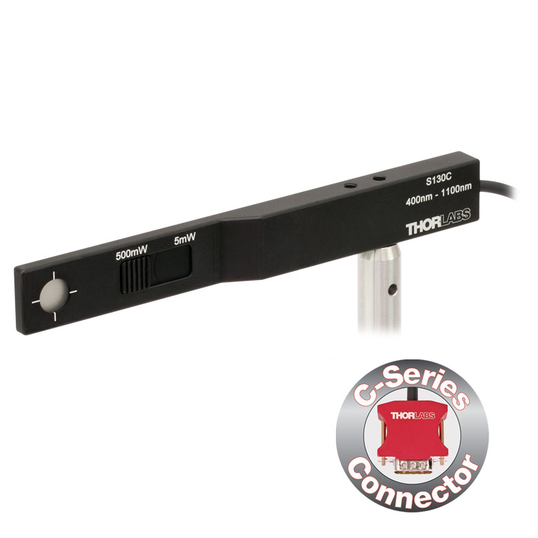
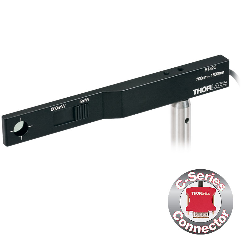
| Item #a | S116C | |
|---|---|---|
| Sensor Image (Click the Image to Enlarge) |
|
|
| Aperture Size | Ø6 mm | |
| Wavelength Range | 400 - 1100 nm | |
| Power Range | 20 nW - 50 mW | |
| Detector Type | Si Photodiode | |
| Linearity | ±0.5% | |
| Resolution | 1 nWb | |
| Measurement Uncertaintyc | ±3% (451 - 1000 nm) ±5% (400 - 450 nm, 1001 - 1100 nm) |
|
| Responsivityd (Click for Plot) |
Raw Data |
|
| Coating/Diffuser | Absorptive ND (NG9) | |
| Housing Dimensions (L x W x T) |
70.0 mm x 11.0 mm x 8.9 mm; 10.0 mm Width and 4.5 mm Thickness on Sensor Side |
|
| Active Detector Area | 7 mm x 7 mm | |
| Cable Length | 1.5 m | |
| Mounting Threads | 2 Universal 8-32 / M4 Taps (One on the Back, One on the Bottom), Posts Not Included |
|
| Adapters (Not Included) |
SM05A29: Add SM05 Thread to Aperture Fiber Adapters Compatible with SM05A29 Adapter: PM20-FC2, PM20-FC, PM20-APC2, PM20-APC, PM20-SMA, PM20-ST, PM20-SC, and PM20-LC |
|
| Compatible Consoles | PM400, PM100D, PM100A, and PM5020 | |
| Compatible Interfaces | PM101, PM101A, PM101R, PM101U, PM103, PM103A, PM103E, PM103U, and PM100USB | |
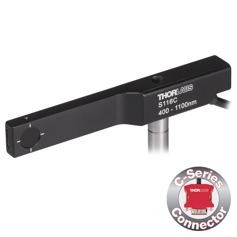
- For Optical Power Measurements in Tiny Spaces Such as 16 mm Cage Systems
- Wavelength Range: 400 - 1100 nm
- Very Slim Design: 10.0 mm Wide and 4.5 mm Thin on Sensor Side
- Silicon Photodiode with Ø6 mm Sensor Aperture
- Designed for Power Measurements for Low Power Lasers
- Post Mountable via 8-32 (M4) Taps
- SM05A29 Adapter with External SM05 (0.535"-40) Threading Available Separately (More Details)
- See the Full Web Presentation for More Information
The S116C Compact Slim Photodiode Power Sensor is designed to take optical source power measurements in locations where space and accessibility are at a premium. The 4.5 mm thin photodiode sensor can fit between the rods of a 16 mm cage system, as seen in the application photo below, as well as through the side openings of our slotted Ø1/2" lens tubes (Item #s SM05L20C and SM05L30C). This sensor also features a Ø6 mm sensor aperture.
A separately available SM05A29 adapter can be attached by two 0.05" (1.3 mm) hex setscrews to an S116C power sensor to mount fiber adapters, light shields, filters or any other SM05-threaded (0.535"-40) mechanics or optics. The adapter mounted on the S116C power sensor is shown below.
Each sensor is shipped with NIST- and PTB-traceable calibration data. The included data is determined with the help of a certified reference diode, which corresponds to the spectral range of the sensor to be calibrated. Thorlabs offers a recalibration service for these photodiode power sensors, which can be ordered below (see Item # CAL-PD for Si sensors).
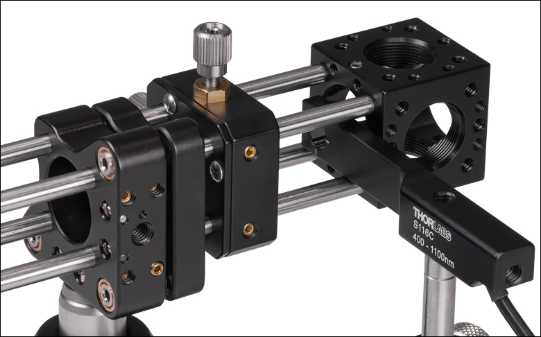
Click to Enlarge S116C Sensor in a 16 mm Cage System


Click for Details
Using the engraved alignment target on the back of the sensor housing, a user can position the stage so that when the sensor is flipped, the beam strikes the center of the sensor. The S170C sensor is shown in this image.
- Designed to Measure Optical Power at the Sample Plane of a Microscope
- Silicon Photodiode with Large 18 mm x 18 mm Active Area
- Sensor Housing Dimensions: 76.0 mm x 25.2 x 5.0 mm
- Novel Optical Design Accommodates High NA Objectives
- Information Stored in Connector
- Sensor Data
- NIST- and PTB-Traceable Calibration Data
- Post Mountable via 8-32 (M4 x 0.7) Tap
The Microscope Slide Power Sensor Heads with silicon photodiodes are designed to measure the power at the sample plane in microscopy setups. The S170C sensor can detect wavelengths from 350 nm to 1100 nm at optical powers from 10 nW to 150 mW, while the S171C sensor can detect wavelengths from 400 nm to 1100 nm at powers from 1 nW to 15 mW. The NS170C sensor is designed to measure the relative peak power of femtosecond lasers with center wavelengths from 780 nm to 1300 nm and average powers from 0.5 mW to 350 mW. Each sensor head's 76.0 mm x 25.2 mm footprint matches that of a standard microscope slide and is compatible with most standard upright and inverted microscopes.
The photodiodes used in the S170C and S171C sensors have 18 mm x 18 mm active areas and are contained in sealed housings behind neutral density (ND) filters. A 20 mm x 20 mm indentation around the surface of the ND filter is sized to accept standard microscope cover slips. An immersion medium (water, glycerol, oil) may be placed in this well directly over the ND filter, or a cover slip may be inserted first to simplify clean up. The gap between the photodiode and the neutral density filter has been filled with an index matching gel in order to prevent internal reflections from causing significant measurement errors when using high NA objectives with oil or water.
The NS170C sensor is designed to measure the relative peak power of two-photon lasers by utilizing a second-order nonlinear β-BBO crystal to convert incident ultrafast NIR pulses into their visible second harmonic. Shortpass filters underneath the β-BBO crystal reject the residual NIR light, allowing only the second harmonic light to transmit down to a large area silicon photodiode sensor. At the entrance of the sensor is a 170 µm thick cover glass sealed to the sensor housing, allowing the sensor to be used with dry, water immersion, and oil immersion objectives. The working distance from the top of the cover glass to the β-BBO crystal is 0.22 mm.
The bottom of each sensor housing features a laser-engraved grid to aid in aligning and focusing the beam. In standard microscopes, this grid can be used for beam alignment before flipping the sensor head to face the objective for power measurements. In inverted microscopes, turn on the transmitted illuminator to align the grid on the detector housing with the beam, thereby centering the sensor in front of the objective. Alternatively, the diffusive surface of the ND filter can be used as a focusing plane.
To avoid damaging the sensor, we recommend positioning it in the light path at a location where the beam is not focused. It is important not to exceed the Max Average Power Density over the beam's spot size for the S170C and S171C sensors, and the Max Peak Power Density for the NS170C sensor (see Specs table below) .
Each sensor is shipped with NIST- or PTB-traceable calibration data. The included data will match the calibration certification of the photodiode used to test the individual sensor. Sensor specifications and the included NIST- or PTB-traceable calibration data are stored in non-volatile memory in the sensor connector and can be read out by the latest generation of Thorlabs power meters. Please note that the NS170C sensor's NIST and PTB calibration is for the visible light incident on the detector; however, the magnitude of that visible light is specific to the illumination conditions of the NIR femtosecond pulses. We recommend yearly recalibration to ensure accuracy and performance, which can be ordered below (see Item # CAL-PD for S170C and S171C sensors, and Item # CAL-NS for the NS170C sensor). Please contact Tech Support for more information.
Thorlabs also offers a Microscope Slide Sensor Head with a thermal sensor; the full presentation can be found here.
| Item #a | S170C | S171C | NS170C |
|---|---|---|---|
| Sensor Image (Click Image to Enlarge) |
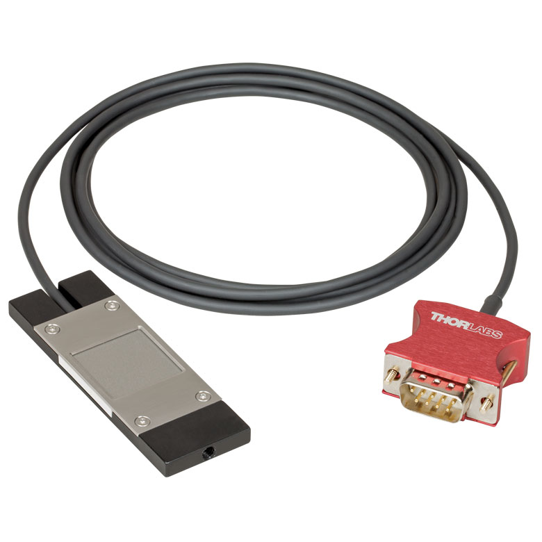 |
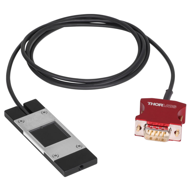 |
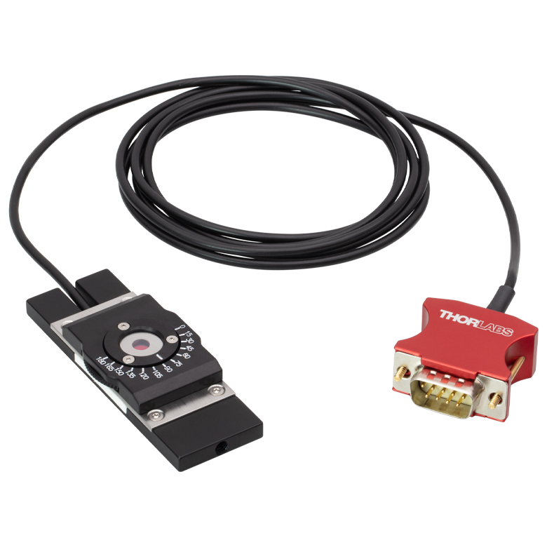 |
| Dimensions | 76.0 mm x 25.2 mm x 5.0 mm (2.99" x 0.99" x 0.20") |
Base: 76.0 mm x 25.2 mm x 5.0 mm (2.99" x 0.99" x 0.20") Overall: 76.0 mm x 30.0 mm x 11.0 mm (2.99" x 1.18" x 0.43") |
|
| Active Detector Area | 18 mm x 18 mm | ||
| Input Aperture | 20 mm x 20 mm | Ø4.5 mm | |
| Wavelength Range | 350 - 1100 nm | 400 - 1100 nm | Laser: 780 - 1300 nm SHG: 390 - 650 nm |
| Optical Power Working Range | 10 nW - 150 mW | 1 nW - 15 mW | Laser: 0.5 - 350 mWb SHG: 10 nW - 5 mW |
| Max Peak Power Densityc | - | - | 10 TW/cm2 |
| Detector Type | Silicon Photodiode | Second-Order Nonlinear Crystal with Silicon Photodiode |
|
| Linearity | ±0.5% | ±0.5%d | |
| Resolution | 1 nWe | 0.5 pWf | 1 nWd,e |
| Measurement Uncertaintyg | ±3% (440 - 980 nm) ±5% (350 - 439 nm) ±7% (981 - 1100 nm) |
±3% (440 - 980 nm)h ±5% (400 - 439 nm)h ±7% (981 - 1100 nm)h |
±3% (440 - 650 nm)d ±5% (390 - 439 nm)d |
| Responsivityi (Click for Plot) |
 Raw Data |
 Raw Data |
 Raw Data |
| Neutral Density Filter | Reflective (OD 1.5) | Absorptive (OD 0.4) | N/A |
| Cable Length | 1.5 m | ||
| Mounting Thread | Universal 8-32 / M4 x 0.7 Tap, Post Not Included | ||
| Compatible Consoles | PM400, PM100D, PM100A, and PM5020 | ||
| Compatible Interfaces | PM101, PM101A, PM101R, PM101U, PM103, PM103A, PM103E, PM103U, and PM100USB | ||
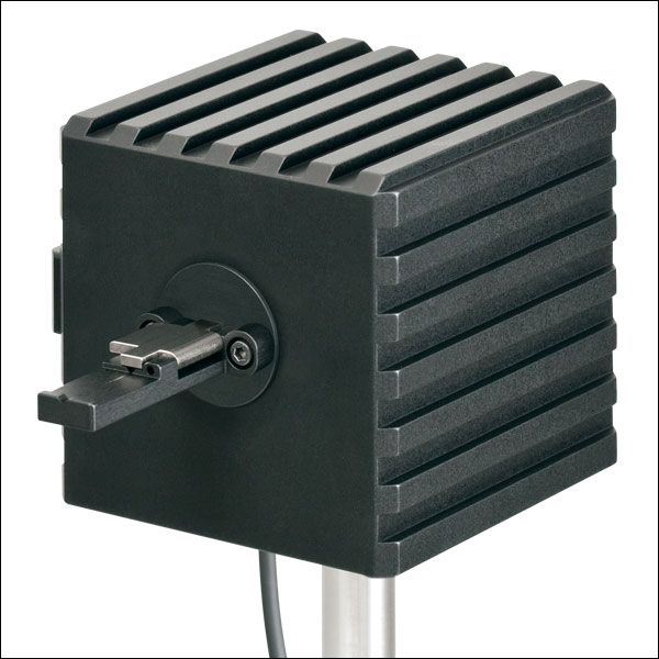
Click to Enlarge
S142C and S140-BFA Bare Fiber Adapter (Sold Separately)
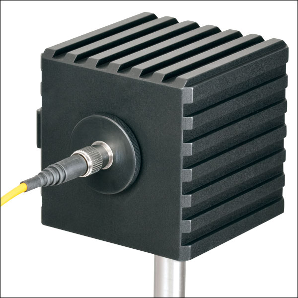
Click to Enlarge
S142C with the S120-FC Fiber Adapter (Included)
- For Measurements Independent of Beam Shape and Entrance Angle
- Integrating Sphere Design Acts as a Diffuser with Minimal Power Loss
- Ø5 mm, Ø7 mm, Ø12 mm, or Ø22 mm Input Sensor Aperture
- Spheres with Apertures ≤Ø12 mm Include a Removable S120-FC Fiber Adapter (FC/PC and FC/APC)
- Fiber Adapters for Terminated and Bare Fiber (See Table Below) are Compatible with Spheres with Apertures ≤Ø12 mm
- See the Full Web Presentation for More Information
These Integrating Sphere Photodiode Power Sensors are the ideal choice for power measurements independent of beam uniformity, divergence angle, beam shape, or entrance angle, making them excellent for use with fiber sources and off-axis free space sources. They feature enhanced shielding to avoid electromagnetic interference and an over-temperature alert sensor to warn against damage and measurement errors due to overheating of the sensor.
Our integrating spheres are designed for wavelength ranges from the visible through the NIR. Sensor heads for use between 350 and 2500 nm use a single Ø1" or Ø2" sphere made from Zenith® PTFE and feature a black housing to minimize reflected light around the entrance aperture. These sensors use either a silicon photodiode for detection in the 350 - 1100 nm range or an InGaAs photodiode for detection in the 800 - 1700 nm, 900 - 1650 nm, or 1200 - 2500 nm wavelength range.
The S180C integrating sphere for 2.9 - 5.5 µm uses two connected, gold-plated Ø20 mm spheres, with an entrance port in the first sphere and a port for the MCT (HgCdTe) detector located in the second sphere. Compared to single-sphere designs, the two-sphere configuration improves device sensitivity by minimizing the internal sphere surface area while still effectively shielding the detector from direct illumination. This design reduces the effect of input angle, divergence, and beam shape on the measurement result by effectively shielding the photodiode without the use of a baffle or other shielding mechanism.
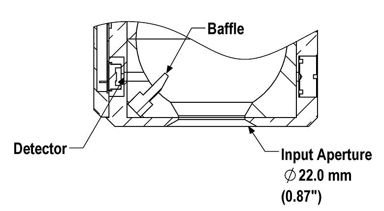
Click to Enlarge
A baffle on the S142CL and S145CL spheres blocks light from directly hitting the detector.
The integrating spheres with Ø5 mm, Ø7 mm, or Ø12 mm apertures feature large active detector areas, and externally SM1-threaded (1.035"-40) adapters for compatibility with the included S120-FC fiber adapter. Because of the large active detector areas of these sensors, the included S120-FC fiber adapter can be used with FC/PC- or FC/APC-terminated fiber. The externally SM1-threaded adapter can be removed using a size 1 screwdriver to place components closer to the window.
The S142CL and S145CL integrating spheres feature a large Ø22 mm input aperture and a baffle within the sphere which prevents direct illumination of the photodiode. The large aperture and baffle enable measurements of large and divergent beams, such as those emitted from LED and VCSEL light sources. The input face of the detectors have four 4-40 threads for mounting 30 mm cage system components. Additionally, insertion of a second or third port in the sensor head is possible on request, please contact Tech Support for details.
Each sensor is shipped with NIST- or PTB-traceable calibration data. The included data will match the calibration certification of the photodiode used to test the individual sensor. NIST- or PTB-traceable data is stored in the sensor connector. Thorlabs offers a recalibration service for these photodiode power sensors, which can be ordered below (see Item # CAL-PD for Si sensors, Item # CAL-IRPD for InGaAs sensors, and Item # CAL-MIRPD for extended InGaAs or MCT sensors).
| Item #a | S140C | S142C | S142CL | S144C | S145C | S145CL | S146C | S148C | S180C | |
|---|---|---|---|---|---|---|---|---|---|---|
| Sensor Image (Click the Image to Enlarge) |
 |
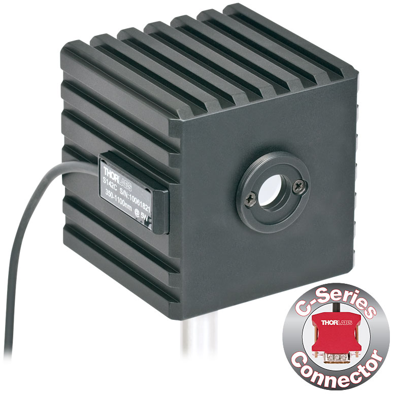 |
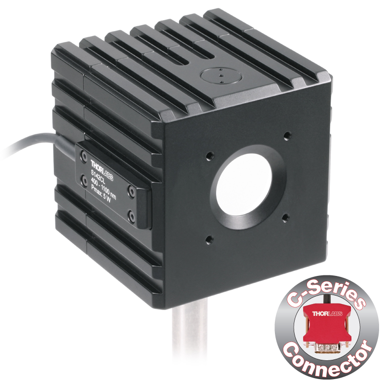 |
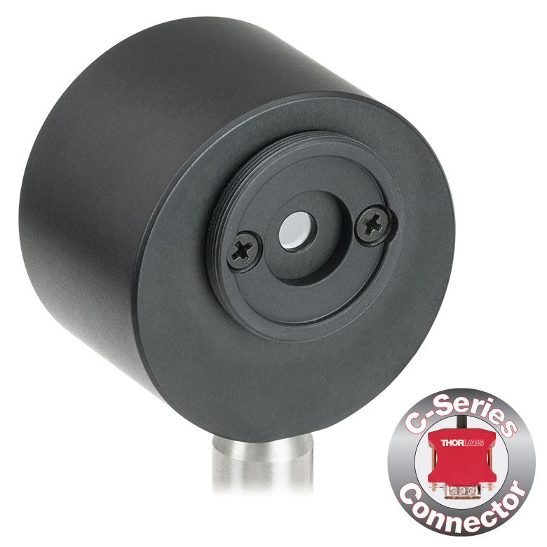 |
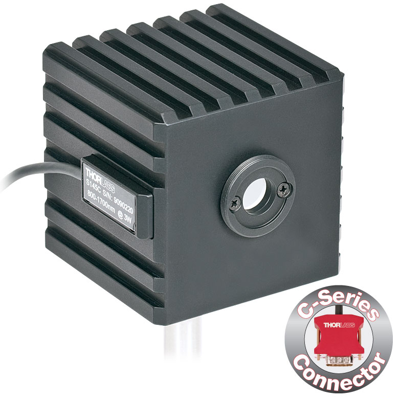 |
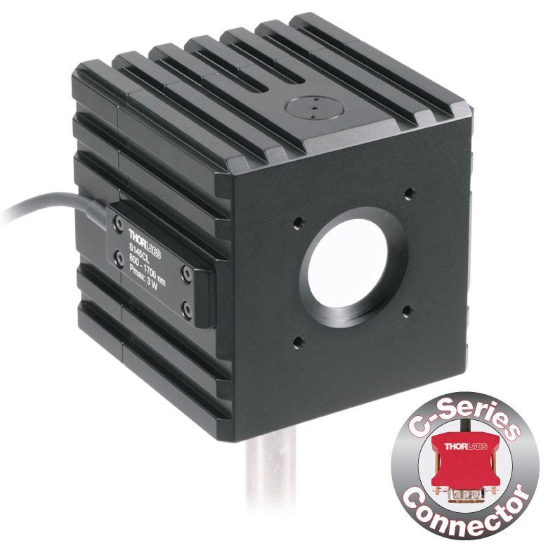 |
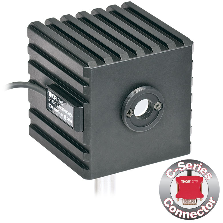 |
|
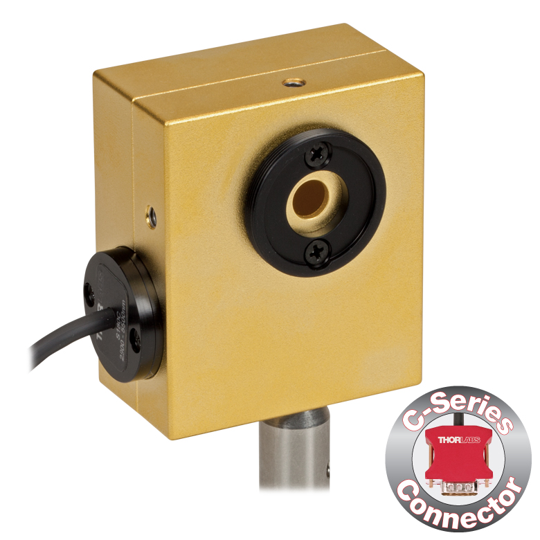 |
|
| Aperture Size | Ø5 mm | Ø12 mm | Ø22 mm | Ø5 mm | Ø12 mm | Ø22 mm | Ø12 mm | Ø5 mm | Ø7 mm | |
| Wavelength Range | 350 - 1100 nm | 400 - 1100 nm | 800 - 1700 nm | 900 - 1650 nm | 1200 - 2500 nm | 2.9 µm - 5.5 µm | ||||
| Power Range | 1 µW - 500 mW | 1 µW - 5 W | 10 µW - 5 W | 1 µW - 500 mW | 1 µW - 3 W | 10 µW - 3 W | 10 µW - 20 W | 1 µW - 1 W | 1 µW - 3 W | |
| Detector Type | Si Photodiode | Si Photodiode with Baffle | InGaAs Photodiode | InGaAs Photodiode with Baffle | InGaAs Photodiode | Extended InGaAs Photodiode | MCT (HgCdTe) Photodiode |
|||
| Linearity | ±0.5% | |||||||||
| Resolutionb | 1 nW | 10 nW | 1 nW | 10 nW | 1 nW | 10 nW | ||||
| Measurement Uncertaintyc,d |
±3% (440 - 980 nm) ±5% (350 - 439 nm) ±7% (981 - 1100 nm) |
±3% (440 - 980 nm) ±5% (400 - 439 nm) ±7% (981 - 1100 nm) |
±5% | |||||||
| Responsivitye (Click for Plot) |
 Raw Data |
 Raw Data |
 Raw Data |
 Raw Data |
 Raw Data |
 Raw Data |
 Raw Data |
 Raw Data |
|
| Integrating Sphere Material (Size) |
Zenith® PTFE (Ø1") |
Zenith® PTFE (Ø2") |
Zenith® PTFE (Ø1") |
Zenith® PTFE (Ø2") |
Zenith® PTFE (Ø1") |
Gold Plating (Two Ø20 mm Spheres) |
||||
| Head Temperature Measurement |
NTC Thermistor 4.7 kΩ | |||||||||
| Housing Dimensions |
Ø45 mm x 30.5 mm | 70 mm x 74 mm x 70 mm | Ø45 mm x 30.5 mm | 70 mm x 74 mm x 70 mm | Ø45 mm x 30.5 mm | 59.0 mm x 50.0 mm x 28.5 |
||||
| Active Detector Area | 3.6 mm x 3.6 mm | Ø2 mm | Ø3 mm | Ø1 mm | Ø1 mm | 1 mm x 1 mm | ||||
| Cable Length | 1.5 m | |||||||||
| Mounting Thread | Separate 8-32 and M4 Taps, Posts Not Included | Universal 8-32 / M4 Thread, Post Not Included | Separate 8-32 and M4 Taps, Posts Not Included | Universal 8-32 / M4 Thread, Post Not Included | Separate 8-32 and M4 Taps, Posts Not Included | Universal |
||||
| Aperture Thread | Included Adapter with SM1 (1.035"-40) External Thread | None | Included Adapter with SM1 (1.035"-40) External Thread | None | Included Adapter with SM1 (1.035"-40) External Thread | |||||
| Compatible Fiber Adapters |
S120-FC (Included) S120-FC2, S120-APC2, S120-APC, S120-SMA, S120-ST, S120-SC, S120-LC, S120-25, and S140-BFA (Not Included) |
None | S120-FC (Included) S120-FC2, S120-APC2, S120-APC, S120-SMA, S120-ST, S120-SC, S120-LC, S120-25, and S140-BFA (Not Included) |
None | S120-FC (Included) S120-FC2, S120-APC2, S120-APC, S120-SMA, S120-ST, S120-SC, S120-LC, S120-25, and S140-BFA (Not Included) |
|||||
| Compatible Consoles | PM400, PM100D, PM100A, and PM5020 | |||||||||
| Compatible Interfaces | PM101, PM101A, PM101R, PM101U, PM103, PM103A, PM103E, PM103U, and PM100USB | |||||||||
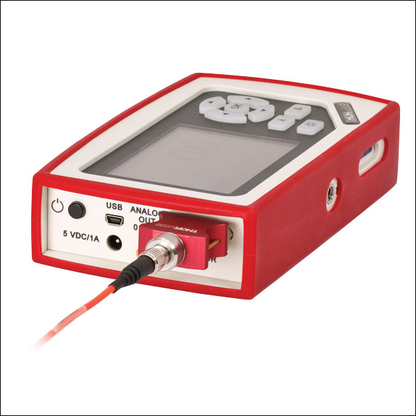
Click to Enlarge
PM100D with S150C Sensor and FC Cable
- For Fiber-Based Optical Power Measurements
- Compact Sensor Integrated into the Connector
- Integrated Design for use in the Field and Lab
- Includes PM20-FC Fiber Adapter
- S150C and S151C Sensors also Include PM20-SMA Adapters
- Compatible FC/APC, LC/PC, SC/PC, and ST®* Fiber Adapters Also Available (See Table Below)
- See the Full Web Presentation for More Information
The S15xC Compact Fiber Photodiode Power Sensor is designed to take power measurements from a wide variety of fiber coupled sources. The compact sensor, integrated into the power meter connector, features a unique integrated design housing the photodiode sensor, fiber coupling, and NIST-traceable data. Standard FC (and SMA - S150C and S151C) connectors are easily interchanged with a variety of standard fiber connectors.
Thorlabs offers a recalibration service for these photodiode power sensors, which can be ordered below (see Item # CAL-PD for Si sensors and Item # CAL-IRPD for InGaAs sensors).
*ST® is a registered trademark of Lucent Technologies, Inc.
| Item #a | S150C | S151C | S154C | S155C |
|---|---|---|---|---|
| Sensor Image (Click the Image to Enlarge) |
|
|
|
|
| Included Connectors | FCb & SMA | FCb | ||
| Wavelength Range | 350 - 1100 nm | 400 - 1100 nm | 800 - 1700 nm | |
| Power Range | 100 pW to 5 mW (-70 dBm to +7 dBm) |
1 nW to 20 mW (-60 dBm to +13 dBm) |
100 pW to 3 mW (-70 dBm to +5 dBm) |
1 nW to 20 mW (-60 dBm to +13 dBm) |
| Detector Type | Si Photodiode | InGaAs Photodiode | ||
| Linearity | ±0.5% | |||
| Resolutionc | 10 pW (-80 dBm) | 100 pW (-70 dBm) | 10 pW (-80 dBm) | 100 pW (-70 dBm) |
| Measurement Uncertaintyd | ±3% (440 - 980 nm) ±5% (350 - 439 nm) ±7% (981 - 1100 nm) |
±3% (440 - 980 nm) ±5% (400 - 439 nm) ±7% (981 - 1100 nm) |
±5% | |
| Responsivityf (Click for Details) |  Raw Data |
 Raw Data |
 Raw Data |
 Raw Data |
| Coating/Diffuser | N/A | Absorptive ND (Schott NG3) | N/A | |
| Head Temperature Measuremente | NTC Thermistor 3 kΩ | |||
| Aperture Thread | External SM05 (0.535"-40) | |||
| Fiber Adapters | Included: PM20-FC and PM20-SMA Optional: PM20-FC2, PM20-APC2, PM20-APC, PM20-ST, PM20-SC, and PM20-LC |
Included: PM20-FC Optional: PM20-FC2, PM20-APC2, PM20-APC, PM20-SMA, PM20-ST, PM20-SC, and PM20-LC |
||
| Compatible Consoles | PM400, PM100D, PM100A, and PM5020 | |||
| Compatible Interfaces | PM101, PM101A, PM101R, PM101U, PM103, PM103A, PM103E, PM103U, and PM100USB | |||
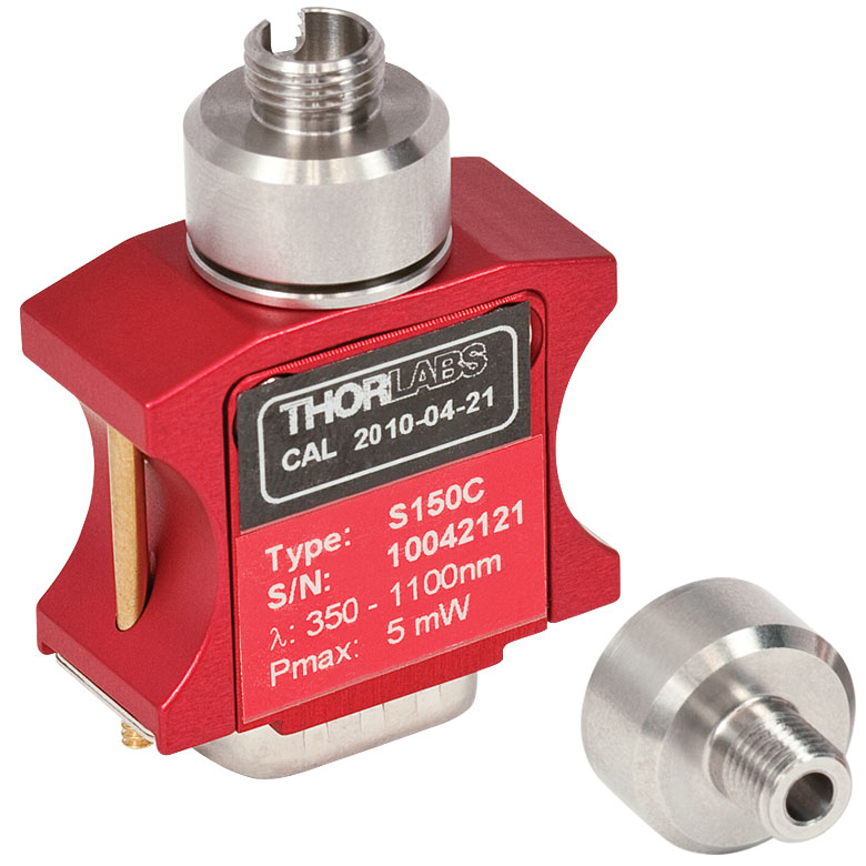
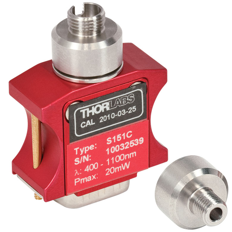
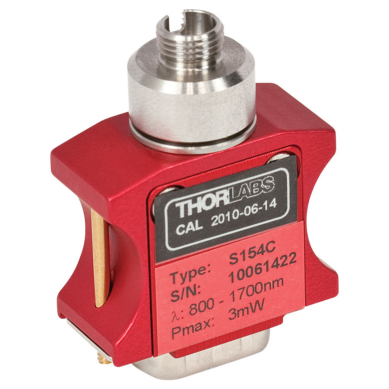

| Item #a | S175C |
|---|---|
| Sensor Image (Click Image to Enlarge) |
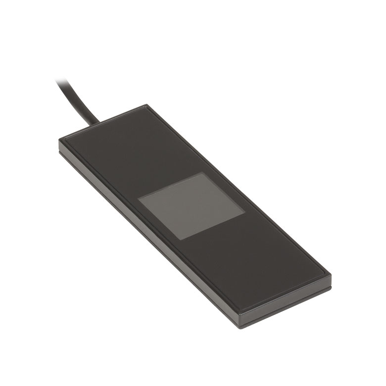 |
| Active Detector Area | 18 mm x 18 mm |
| Wavelength Range | 0.3 - 10.6 µm |
| Power Range | 100 µW - 2 W |
| Detector Type | Thermal Surface Absorber (Thermopile) |
| Linearity | ±0.5% |
| Resolutionb | 10 µW |
| Measurement Uncertaintyc | ±3% @ 1064 nm; ±5% @ 300 nm - 10.6 µm |
| Response Time | 3 s (<2 s from 0 to 90%) |
| Housing Dimensions | 76 mm x 25.2 mm x 4.8 mm (2.99" x 0.99" x 0.19") |
| Cable Length | 1.5 m |
| Housing Features | Integrated Glass Cover Engraved Laser Target on Back |
| Post Mounting | N/A |
| Cage Mounting | N/A |
| Aperture Thread | N/A |
| Compatible Consoles | PM400, PM100D, PM100A, and PM5020 |
| Compatible Interfaces | PM101, PM101A, PM101R, PM101U, PM102, PM102A, PM102U, and PM100USB |
Click to Enlarge
Typical absorption curve for the S175C (glass and absorber). Note that this curve is representative, and the actual absorption across the spectrum will vary from unit to unit.

Click to Enlarge
The back of the S175C housing is engraved with the sensor specifications and a target for centering the beam on the sensor.
- Wavelength Range: 300 nm - 10.6 µm
- Sensitive to Optical Powers from 100 µW to 2 W
- Designed to Measure Optical Power in the Sample Plane of a Microscope
- Thermal Sensor with 18 mm x 18 mm Active Area
- 76.0 mm x 25.2 mm Footprint Matches Standard Microscope Slides
- Information Stored in Connector
- Sensor Data
- NIST- and PTB-Traceable Calibration Data
- See the Full Web Presentation for More Information
The S175C Microscope Slide Thermal Power Sensor Head is designed to measure the power at the sample in microscopy setups. The thermal sensor can detect wavelengths between 300 nm and 10.6 µm at optical powers between 100 µW and 2 W. The sensor head's 76.0 mm x 25.2 mm footprint matches that of a standard microscope slide and is compatible with most standard upright and inverted microscopes.
The thermal sensor has an 18 mm x 18 mm active area and is contained in a sealed housing behind a glass cover. An immersion medium (water, glycerol, oil) may be placed over the glass cover plate.
As seen in the image to the right, the bottom of the sensor housing features a laser-engraved target to aid in aligning and focusing the beam. In standard microscopes, the target can be used for beam alignment before flipping the sensor head to face the objective for power measurements. In inverted microscopes, turn on the trans-illumination lamp and align the target on the detector housing with the beam; this will center the sensor in front of the objective.
Sensor specifications and the NIST- and PTB-traceable calibration data are stored in non-volatile memory in the sensor connector and can be read out by the latest generation of Thorlabs power meters. We recommend yearly recalibration to ensure accuracy and performance. Calibration may be ordered using the CAL-THPY recalibration service available below. Please contact technical support for more information.
Thorlabs also offers a Microscope Slide Sensor Head with a photodiode sensor for low-power, high-resolution measurements; the full presentation may be found here.
| Item #a | S401C | S405C |
|---|---|---|
| Sensor Image (Click the Image to Enlarge) |
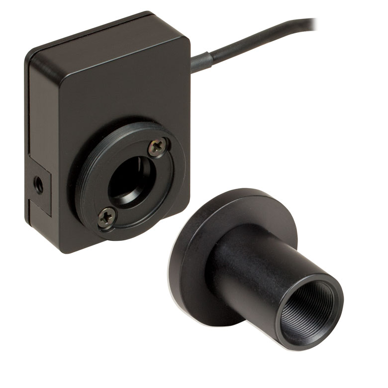 |
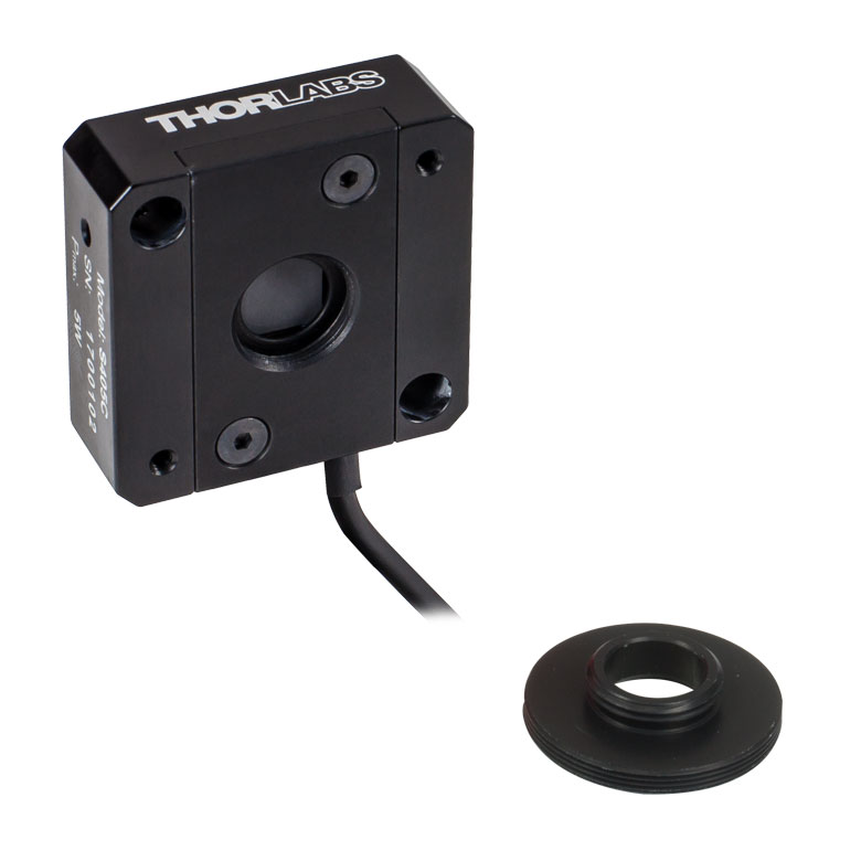 |
| Wavelength Range | 190 nm - 20 µm | 190 nm - 20 µm |
| Optical Power Range | 10 µW - 1 W (3 Wb) | 100 µW - 5 W |
| Input Aperture Size | Ø10 mm | Ø10 mm |
| Active Detector Area |
10 mm x 10 mm | 10 mm x 10 mm |
| Max Optical Power Density | 500 W/cm² (Avg.) | 1.5 kW/cm² (Avg.) |
| Detector Type | Thermal Surface Absorber (Thermopile) with Background Compensation |
Thermal Surface Absorber (Thermopile) |
| Linearity | ±0.5% | ±0.5% |
| Resolutionc | 1 µW | 5 µW |
| Measurement Uncertaintyd | ±3% @ 1064 nm ±5% @ 190 nm - 10.6 µm |
±3% @ 1064 nm ±5% @ 250 nm - 17 µm |
| Response Timee | 1.1 s | 1.1 s |
| Cooling | Convection (Passive) | |
| Housing Dimensions (Without Adapter) |
(1.30" x 1.69" x 0.59") |
40.6 mm x 40.6 mm x 16.0 mm (1.60" x 1.60" x 0.63") |
| Temperature Sensor (In Sensor Head) |
NTC Thermistor | NTC Thermistor |
| Cable Length | 1.5 m | |
| Post Mounting | Universal 8-32 / M4 Taps (Post Not Included) |
Universal 8-32 / M4 Taps (Post Not Included) |
| 30 mm Cage Mounting | - | Two 4-40 Tapped Holes & Two Ø6 mm Through Holes |
| Aperture Threads | - | Internal SM05 |
| Accessories | Externally SM1-Threaded Adapter Light Shield with Internal SM05 Threading |
Externally SM1-Threaded Adapter |
| Compatible Consoles | PM400, PM100D, PM100A, and PM5020 | |
| Compatible Interfaces | PM101, PM101A, PM101R, PM101U, PM102, PM102A, PM102U, and PM100USB | |
- High Resolution of 1 μW or 5 μW
- S401C and S405C Have Thermistors Used to Monitor Temperature of Sensor Head
- S401C: Background Compensation for Low-Drift Measurements
- S405C: Accommodates Average Optical Power Densities up to 1.5 kW/cm²
- See the Full Web Presentation for More Information

Click to Enlarge
S401C Thermal Sensor with Included Light Shield
Thorlabs offers two broadband thermal power sensors designed to measure low optical power sources with high resolution. Each thermal sensor's broadband coating has a flat spectral response over a wide wavelength range, as shown in the plot below.
An aperture size of Ø10 mm allows for easy alignment and measurement of large-spot-size laser sources. For easy integration with Thorlabs' lens tube systems and SM1-threaded (1.035"-40) fiber adapters, each sensor has either external SM1 threading or includes an externally SM1-threaded adapter.
The S401C uses active thermal background compensation to provide low-drift power measurements. This is implemented through the use of two similar sensor circuits. One sensor circuit is the type all thermal power sensors share: it measures heat flow from light absorber to heat sink. The other sensor circuit monitors the ambient temperature. It is located within the housing and measures heat flow from heat sink towards the absorber. The measurements of the two sensor circuits are subtracted, which minimizes the effect of thermal drift on the laser power measurement. (For information about how the external thermal disturbances can affect thermal power sensor readings, see the Operation tab.) The broadband coating used on this thermal sensor offers high absorption at wavelengths between 0.19 and 20 µm (shown in the graph), which makes the sensor ideal for use with aligning and measuring Mid-IR Quantum Cascade Lasers (QCLs). The included, internally SM05-threaded (0.535"-40) light shield is shown in the photo to the right.
The S405C has internal SM05 (0.535"-40) threading that is directly compatible with SM05 lens tubes, and it can also connect directly to Thorlabs' 30 mm Cage Systems.
Thorlabs offers a recalibration service for these sensors, which can be ordered below (see Item # CAL-THPY).
Click to Enlarge
The S405 shares the same absorption curve with the S415C, S425C, and S245C-L. (All are sold below.)
| Item #a | S415C | S425C |
|---|---|---|
| Sensor Image (Click Image to Enlarge) |
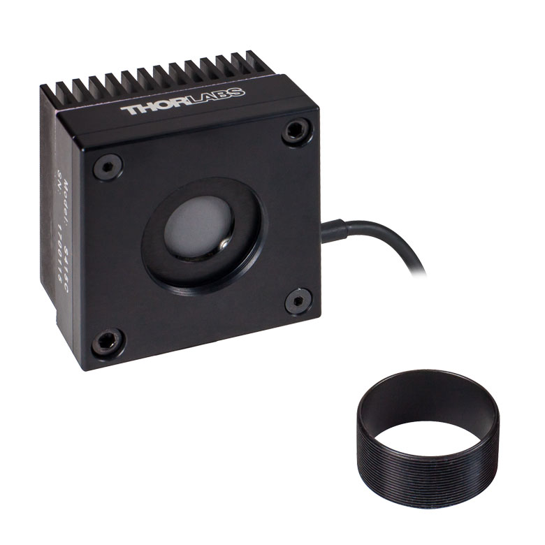 |
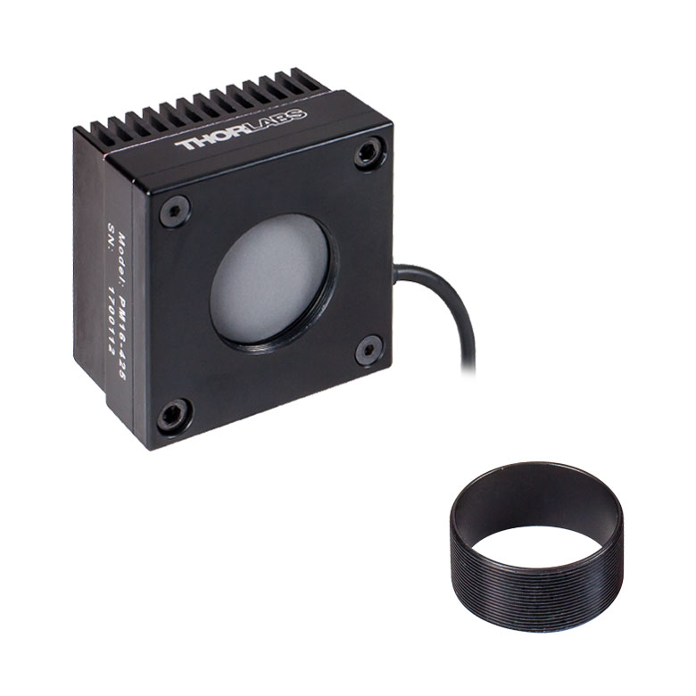 |
| Wavelength Range | 190 nm - 20 µm | 190 nm - 20 µm |
| Optical Power Range | 2 mW - 10 W (20 Wb) | 2 mW - 10 W (20 Wb) |
| Input Aperture Size | Ø15 mm | Ø25.4 mm |
| Active Detector Area |
Ø15 mm | Ø27 mm |
| Max Optical Power Density |
1.5 kW/cm² (Avg.) | 1.5 kW/cm² (Avg.) |
| Detector Type | Thermal Surface Absorber (Thermopile) | |
| Linearity | ±0.5% | ±0.5% |
| Resolutionc | 100 µW | 100 µW |
| Measurement Uncertaintyd |
±3% @ 1064 nm ±5% @ 250 nm - 17 µm |
±3% @ 1064 nm ±5% @ 250 nm - 17 µm |
| Response Timee | 0.6 s | 0.6 s |
| Cooling | Convection (Passive) | |
| Housing Dimensions (Without Adapter) |
(2.00" x 2.00" x 1.38") |
(2.00" x 2.00" x 1.38") |
| Temperature Sensor (In Sensor Head) |
NTC Thermistor | |
| Cable Length | 1.5 m | |
| Post Mounting | Universal 8-32 / M4 Taps (Post Not Included) |
Universal 8-32 / M4 Taps (Post Not Included) |
| 30 mm Cage Mounting | - | - |
| Aperture Threads | Internal SM1 | Internal SM1 |
| Removable Heatsink | Yes | Yes |
| Accessories | Externally SM1-Threaded Adapter | Externally SM1-Threaded Adapter |
| Compatible Consoles | PM400, PM100D, PM100A, and PM5020 | |
| Compatible Interfaces | PM101, PM101A, PM101R, PM101U, PM102, PM102A, PM102U, and PM100USB | |
- 100 µW Optical Power Resolution
- Thermistors Used to Monitor Temperature of Sensor Head
- Removable Heat Sinks Included
- See the Full Web Presentation for More Information
These thermal power sensors are designed for general broadband power measurements of low and medium power light sources. All include an externally SM1-threaded (1.035"-40) adapter, with threading concentric with the input aperture. The adapters are useful for mounting Ø1" Lens Tubes and Fiber Adapters (available below). The apertures of the S415C and S425C have internal SM1 threading.
These sensors operate with fast (<0.6 s) natural response times, and their removable heat sinks provide a high degree of flexibility to those interested in integrating them into custom setups or replacing the included heat sink with one that is water or fan cooled. If replacing the heat sink, please note that the replacement must provide heat dissipation adequate for the application.
Thorlabs offers a recalibration service for these sensors, which can be ordered below (see Item # CAL-THPY).
Click to Enlarge
The absorption curves of each of the thermal power sensors designed for use with low and medium power optical sources.
Click to Enlarge
The absorption curves of each of the thermal power sensors designed for use with low and medium power optical sources.
- Thermistors Used to Monitor Temperature of Sensor Head
- S322C Has 4-40 Taps for Use with Our 30 mm Cage Systems
- S350C Has Ø40 mm Aperture Well Suited to Excimer and Other Lasers with Large Spot Sizes
- S425C-L Features Removable Heat Sink
- S322C is Fan Cooled with an Optical Power Range up to 200 W
- See the Full Web Presentation for More Information
These thermal power sensors are designed for general broadband power measurements of low and medium power light sources. With the exception of the S350C, all include an adapter with external SM1 (1.035"-40) threading concentric with the input aperture. This allows the sensors to be integrated into existing Ø1" lens tube systems in addition to being compatible with fiber adapters (available below). The aperture of the S425C-L has internal SM1 threading.
The S425C-L operates with a fast (<0.6 s) natural response time and has a removable heat sink, which provides a high degree of flexibility to those interested in integrating them into custom setups or replacing the included heat sink with one that is water or fan cooled. If replacing the heat sink, please note that the replacement must provide heat dissipation adequate for the application.
Thorlabs offers a recalibration service for these sensors, which can be ordered below (see Item # CAL-THPY).
| Item #a | S350C | S425C-L | S322C |
|---|---|---|---|
| Sensor Image (Click Image to Enlarge) |
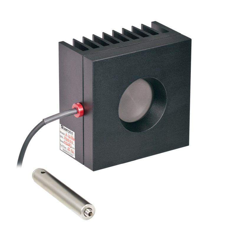 |
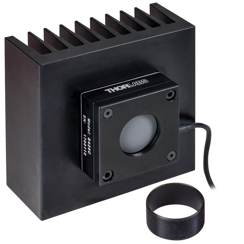 |
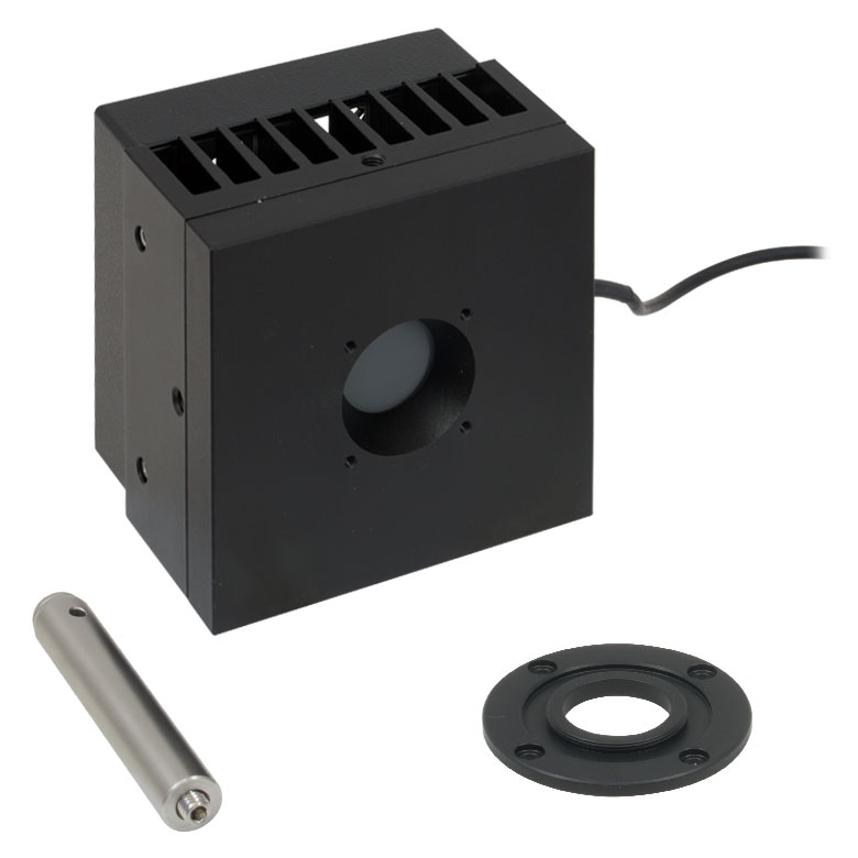 |
| Wavelength Range | 190 nm- 1.1 µm, 10.6 µm | 190 nm - 20 µm | 250 nm - 11 µm |
| Optical Power Range | 10 mW - 40 W (60 Wb) | 2 mW - 50 W (75 Wb) | 100 mW - 200 W (250 Wb) |
| Input Aperture Size | Ø40 mm | Ø25.4 mm | Ø25 mm |
| Active Detector Area |
Ø40 mm | Ø27 mm | Ø25 mm |
| Max Optical Power Density | 2 kW/cm² (Avg.) | 1.5 kW/cm² (Avg.) | 4 kW/cm² (Avg., CO2) |
| Detector Type | Thermal Surface Absorber (Thermopile) | ||
| Linearity | ±1% | ±0.5% | ±1% |
| Resolutionc | 1 mW | 100 µW | 5 mW |
| Measurement Uncertaintyd | ±3% @ 1064 nm ±5% @ 190 nm - 1100 nm, 10.6 µm |
±3% @ 1064 nm ±5% @ 250 nm - 17 µm |
±3% @ 1064 nm ±5% @ 266 nm - 1064 nm |
| Response Timee | 9 s (1 s from 0 to 90%) |
0.6 s | 5 s (1 s from 0 to 90%) |
| Cooling | Convection (Passive) | Forced Air with Fanf | |
| Housing Dimensions (Without Adapter, if Applicable) |
100 mm x 100 mm x 54.2 mm (3.94" x 3.94" x 2.13") |
100.0 mm x 100.0 mm x 58.0 mm (3.94" x 3.94" x 2.28") |
100 mm x 100 mm x 86.7 mm (3.94" x 3.94" x 3.41") |
| Temperature Sensor (In Sensor Head) |
NTC Thermistor | ||
| Cable Length | 1.5 m | ||
| Post Mounting | M6 Threaded Taps, Includes Ø1/2" Post, 75 mm Long |
Universal 8-32 / M4 Taps (Post Not Included) |
M6 Threaded Taps, Includes Ø1/2" Post, 75 mm Long |
| 30 mm Cage Mounting | - | - | Four 4-40 Tapped Holes |
| Aperture Threads | - | Internal SM1 | - |
| Removable Heatsink | - | Yes | - |
| Accessories | - | Externally SM1-Threaded Adapter | Externally SM1-Threaded Adapter |
| Compatible Consoles | PM400, PM100D, PM100A, and PM5020 | ||
| Compatible Interfaces | PM101, PM101A, PM101R, PM101U, PM102, PM102A, PM102U, and PM100USB | ||
| Item #a | S370C | S470C |
|---|---|---|
| Sensor Image (Click the Image to Enlarge) |
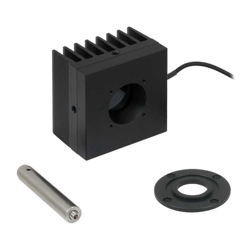 |
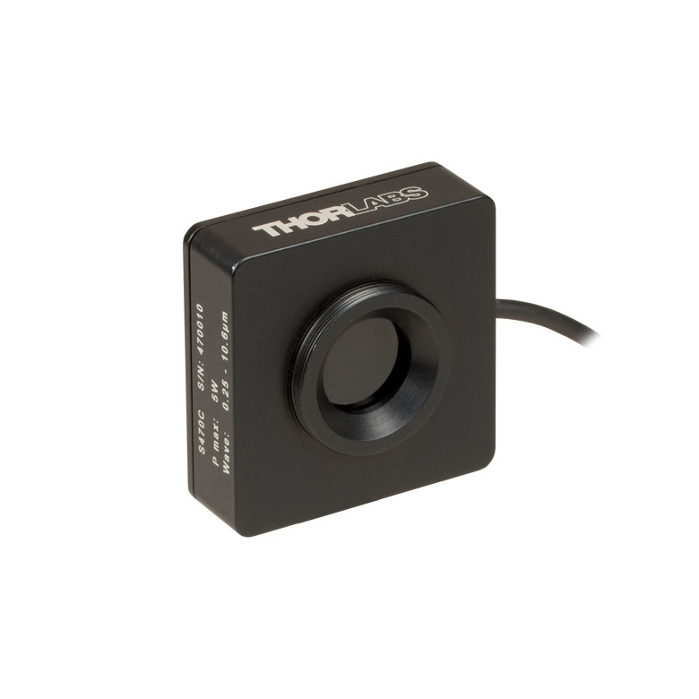 |
| Wavelength Range | 400 nm - 5.2 µm | 250 nm - 10.6 µm |
| Optical Power Range | 10 mW - 10 W (15 Wb) | 100 µW - 5 W (Pulsed and CW) |
| Input Aperture Size | Ø25 mm | Ø15 mm |
| Active Detector Area |
Ø25 mm | Ø16 mm |
| Max Optical Power Density | 35 W/cm² (Avg.); 100 GW/cm² (Peak) | |
| Detector Type | Thermal Volume Absorber (Thermopile) | |
| Linearity | ±1% | ±0.5% |
| Resolutionc | 250 µW | 10 µW |
| Measurement Uncertaintyd | ±3% @ 1064 nm ±5% @ 400 nm - 1064 nm |
±3% @ 1064 nm ±5% @ 250 nm - 10.6 µm |
| Response Timee | 45 s (3 s from 0 to 90%) |
6.5 s (<2 s from 0 to 90%) |
| Cooling | Convection (Passive) | |
| Housing Dimensions (Without Adapter, if Applicable) |
(2.95" x 2.95" x 2.02") |
(1.77" x 1.77" x 0.71") |
| Temperature Sensor (In Sensor Head) |
N/A | N/A |
| Cable Length | 1.5 m | |
| Post Mounting | M6 Threaded Taps, Includes Ø1/2" Post, 75 mm Long |
Universal 8-32 / M4 Tap (Post Not Included) |
| 30 mm Cage Mounting | Four 4-40 Tapped Holes | - |
| Aperture Threads | - | External SM1 |
| Accessories | - | |
| Compatible Consoles | PM400, PM100D, PM100A, and PM5020 | |
| Compatible Interfaces | PM101, PM101A, PM101R, PM101U, PM102, PM102A, PM102U, and PM100USB | |
- Designed for Optical Power Measurements of Nd:YAG Lasers
- Ideal for Applications with High Peak Pulse Powers
- S370C: Ø25 mm Aperture for Large-Spot-Size Beams
- S470C: High-Sensitivity for High-Peak-Power Pulses with Low Average Power
- See the Full Web Presentation for More Information
The S370C and S470C Thermal Sensors are designed to measure short and highly energetic laser pulses. All of these units are post-mountable for free-space applications and feature NIST-traceable data stored in the sensor connector.
These thermal power sensors are unique in that they have thermal volume absorbers, where our other thermal power sensors have thermal surface absorbers. The volume absorber consists of a Schott glass filter. Incident pulses are absorbed and the heat is distributed throughout the volume. In this way, pulses that would have damaged the absorption coating of a thermal surface absorber are safely measured by these thermal volume absorbers.
The S370C features a large Ø25 mm aperture ideal for large-spot-size beams, and it is compatible with average powers from 10 mW to 10 W (CW).
In comparison, the S470C is faster, as the glass absorber volume is reduced and other design parameters have been optimized for speed. This results in a different optical power range, with the ability to measure powers down to 100 µW. The Ø15 mm aperture is of the S470C is smaller, and it has a lower max average power of 5 W. Its 10 µW resolution is better than the 250 µW resolution of the S370C.
Thorlabs offers a recalibration service for these sensors, which can be ordered below (see Item # CAL-THPY).
Click to Enlarge
This absorption curve is shown over a broader wavelength range than the sensors' operating ranges. See the table for the operating wavelength range of each sensor.
| Item #a | S440C | S442C |
|---|---|---|
| Sensor Image (Click the Image to Enlarge) |
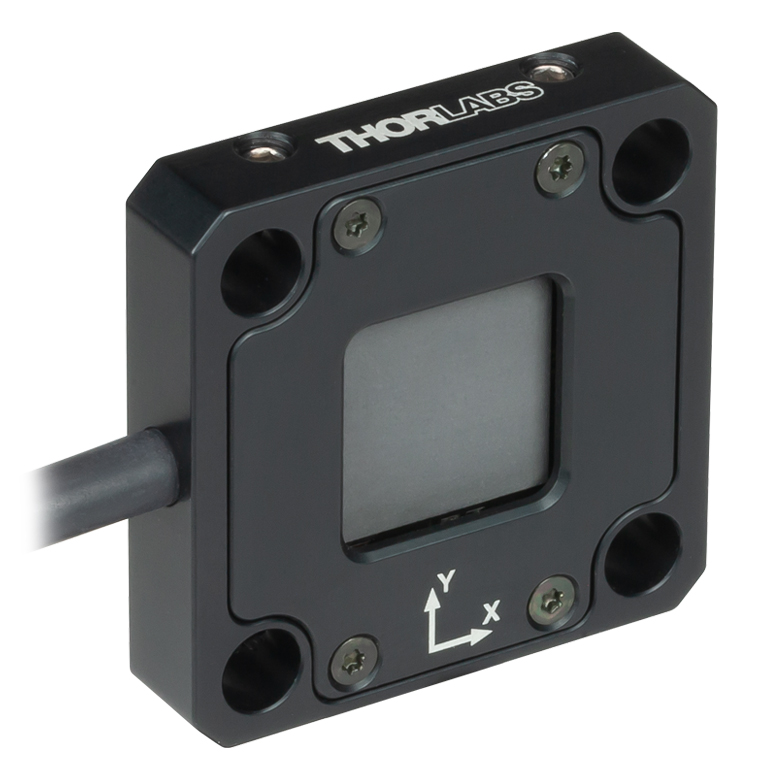 |
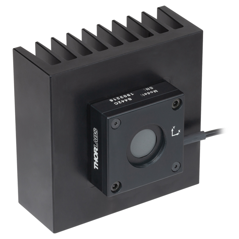 |
| Wavelength Range | 190 nm - 20 µm | |
| Optical Power Range | 0.5 mW - 5 W | 10 mW - 50 W |
| Input Aperture Size | 17 mm x 17 mm | Ø17.5 mm |
| Max Optical Power Density | 1.5 kW/cm2 | |
| Detector Type | Four Thermopiles in Quadrant Configuration | |
| Linearity | ±1% | |
| Resolutionb | 50 µW | 1 mW |
| Measurement Uncertaintyc | ±5% at 1064 nm; ±7% for 250 nm - 17 µm |
|
| Position Resolution | 5 µm | 10 µm |
| Position Accuracyd | 50 µm (Ø1 mm Circle) 200 µm (Ø6 mm Circle) |
100 µm (Ø1 mm Circle) 300 µm (Ø6 mm Circle) |
| Position Repeatabilityd | 15 µm (Ø1 mm Circle) 100 µm (Ø6 mm Circle) |
25 µm (Ø1 mm Circle) 150 µm (Ø6 mm Circle) |
| Response Timee | <1.1 s | <0.6 s |
| Cooling | Convection (Passive) | |
| Housing Dimensions (Without Adapter) |
40.6 mm x 40.6 mm x 8.9 mm (1.60" x 1.60" x 0.35") |
100.0 m x 100.0 mm x 57.8 mm (3.94" x 3.94" x 2.28") |
| Temperature Sensor (In Sensor Head) |
NTC Thermistor | |
| Cable Length | 1.5 m | |
| Post Mounting | One 8-32 / M4 Universal Tap | Two 8-32 / M4 Universal Taps |
| 30 mm Cage Mounting | Four Ø6 mm Through Holes | - |
| Aperture Threads | - | Internal SM1 (1.035"-40) |
| Accessories | - | Externally SM1-Threaded Adapter |
| Compatible Consoles | PM400 and PM5020 | |
| Compatible Interfaces | PM102, PM102A, and PM102U | |
- Segmented Quadrant Position-Sensing Detector
- S440C: High Sensitivity; 30 mm Cage System Compatible
- S442C: High Power; Heat Sink Included
- See the Full Web Presentation for More Information
The S440C and S442C position sensors use thermopiles to obtain high-resolution measurements of a beam's position and power. The detector area consists of four thermopile-based sensors arranged as quadrants of a square. The quadrants are mechanically coupled but electrically isolated; thus, heat is free to flow across the entire active area, but the signal from each quadrant measures the response in only that quadrant's thermopile. The XY position of the beam is determined by comparing the signal intensity measured for each quadrant.
The S440C detector is optimized for high sensitivity from 0.5 mW to 5 W. The housing features four Ø6 mm through holes for compatibility with 30 mm cage systems, as well as an 8-32 / M4 universal tap for post mounting. The S442C detector is compatible with higher power levels from 10 mW up to 50 W. The housing includes a heat sink for superior heat dissipation, as well as two 8-32 / M4 universal taps for post mounting.
Both detectors feature C-Series connectors which contain NIST- and PTB-traceable calibraion data. The sensors can be controlled using the PM400 or PM5020 power meter console or PM102 series power meter interfaces. The system can be configured to display a visual trace of the position over time, a graph of the X and Y positions over time, a table of measurement statistics, or a simple numerical readout of the incident power. See the full web presentation and the PM400 manual for details.
For information on recalibration services for these products, please contact Tech Support.
Click to Enlarge
Click Here for Raw Data
The wavelength range of the data in this graph is limited by the detector used during testing. The thermal position detectors are capable of operating at up to 20 µm.
| Item #a | ES111C | ES120C | ES145C |
|---|---|---|---|
| Sensor Image (Click the Image to Enlarge) |
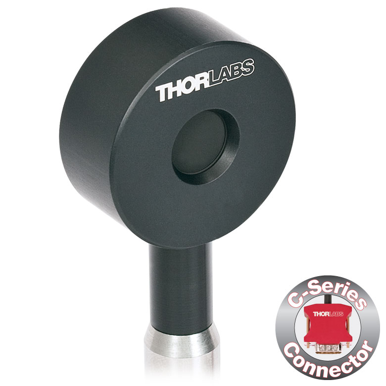 |
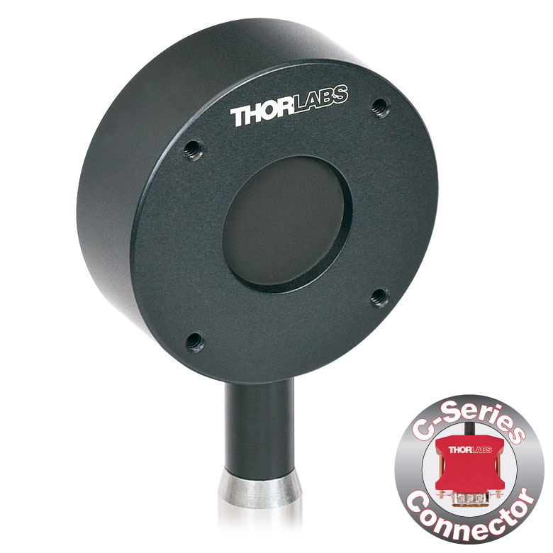 |
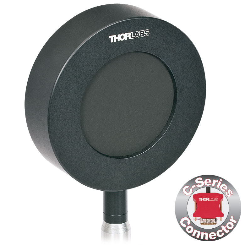 |
| Input Aperture Size | Ø11 mm | Ø20 mm | Ø45 mm |
| Wavelength Range | 0.185 - 25 µm | ||
| Energy Range | 10 µJ - 150 mJ | 100 µJ - 500 mJ | 500 µJ - 2 J |
| Max Repetition Rateb | 40 Hz | 30 Hz | 30 Hz |
| Max Power Density (Pulse Width) |
8 MW/cm2 (10 ns Pulse) |
||
| Max Pulse Energy Density (Pulse Width) |
0.15 J/cm2 (1 µs Pulse) |
||
| Coating (Click for Plot) | Black Broadband | ||
| Resolution | 100 nJ | 1 µJ | 1 µJ |
| Linearity | ±1% | ||
| Measurement Uncertainty | ±5% @ 190 nm - 25 µm | ±5% @ 185 nm - 25 µm | ±5% @ 185 nm - 25 µm |
| Housing Dimensions | Ø36 mm x 16 mm | Ø50 mm x 18 mm | Ø75 mm x 21 mm |
| Active Detector Area | 95.0 mm2 | 314.2 mm2 | 1590.4 mm2 |
| Cable Length | 1.5 m (60") | ||
| Post Mounting | 8-32 Mounting Thread, 8-32 and M4 Insulating Adapters Included | ||
| Cage Mounting | N/A | Four 4-40 Threaded Holes for 30 mm Cage Systems |
N/A |
| Compatible Consoles | PM400, PM100D, and PM5020 | ||
| Compatible Interfaces | PM103, PM103A, PM103E, PM103U, and PM100USB | ||
- For General Purpose Optical Pulse Measurements
- Black Broadband Coating with Flat Response Over a Wide Wavelength Range
- Ø11 mm, Ø20 mm, or Ø45 mm Sensor Area
- BNC Connector for Oscilloscope Use
- Each Sensor Includes:
- C-Series Connector Adapter for Use with Compatible Thorlabs' Consoles (See Table to the Right or the Console Selection Tab)
- Two Electrically Isolating Post Adapters (One Imperial and One Metric)
- See the Full Web Presentation for More Information
The ES1xxC Standard Pyroelectric Sensors are designed to measure pulsed coherent and incoherent sources. Pyroelectric sensors are not suited for CW measurements, as they convert energy from light pulses into voltage pulses. The black broadband coating on these sensors is ideal for low power, wavelength-independent energy measurements due to its flat absorption profile (see the table to the right). Large sensor areas of Ø11 mm, Ø20 mm, or Ø45 mm aid with easy alignment. The sensors can be connected directly to an oscilloscope with a 1 MΩ input resistance via the BNC connector. To accommodate higher repetition rates when connected to an oscilloscope, the load resistance can be reduced. Each energy sensor includes a BNC to C-Series adapter that contains NIST- and PTB-traceable calibration data.
Thorlabs offers a recalibration service for these energy sensors, which can be ordered below (see Item # CAL-THPY).
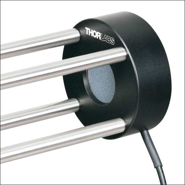
Click to Enlarge
ES220C Sensor Mounted in a 30 mm Cage System
- For High-Energy Optical Pulse Measurements Up to 15 J
- Ceramic Coating with High Damage Threshold for High-Energy-Density (Up to 0.45 J/cm2) Lasers
- Ø20 mm or Ø45 mm Sensor Area
- BNC Connector for Oscilloscope Use
- Each Sensor Includes:
- C-Series Connector Adapter for Use with Compatible Thorlabs' Consoles (See Table Below or the Console Selection Tab)
- Two Electrically Isolating Post Adapters (One Imperial and One Metric)
- See the Full Web Presentation for More Information
The ES2xxC High-Energy Pyroelectric Sensors are designed to measure pulsed coherent and incoherent sources. Pyroelectric sensors are not suited for CW measurements, as they convert energy from light pulses into voltage pulses. A ceramic coating is used for high energy measurements as high as 3 J for the ES220C sensor or 15 J for the ES245C sensor. Large Ø20 mm or Ø45 mm sensor areas aid with easy alignment. The sensors can be connected directly to an oscilloscope with a 1 MΩ input resistance via the BNC connector. To accommodate higher repetition rates when connected to an oscilloscope, the load resistance can be reduced. Each energy sensor also includes a BNC to C-Series adapter that contains NIST- and PTB-traceable calibration data.
Thorlabs offers a recalibration service for these energy sensors, which can be ordered below (see Item # CAL-THPY).
| Item #a | ES220C | ES245C |
|---|---|---|
| Sensor Image (Click the Image to Enlarge) |
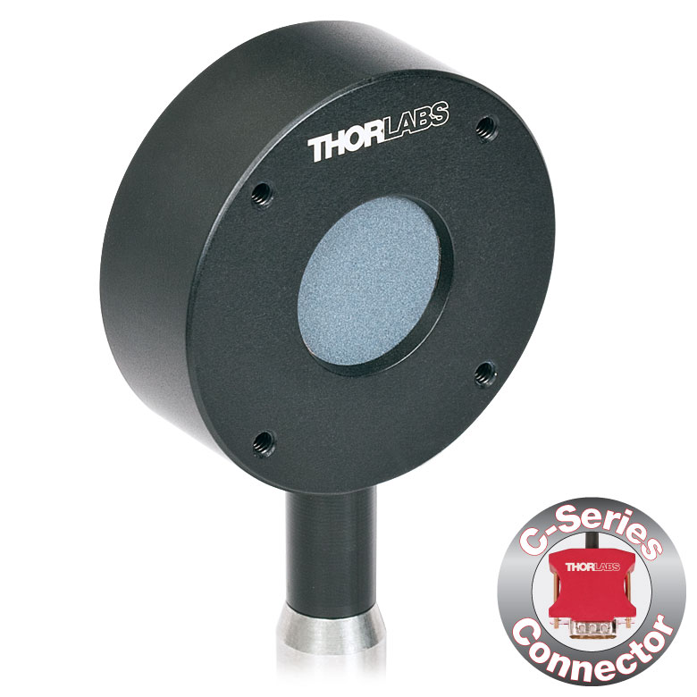 |
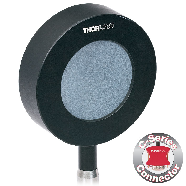 |
| Input Aperture Size | Ø20 mm | Ø45 mm |
| Wavelength Range | 0.185 - 25 µm | |
| Energy Range | 500 µJ - 3 J | 1 mJ - 15 J |
| Max Repetition Rateb | 30 Hz | 30 Hz |
| Max Power Density (Pulse Width) |
65 MW/cm2 (7 ns Pulse @ 355 nm) |
|
| Max Pulse Energy Density (Pulse Width) |
0.45 J/cm2 (7 ns Pulse @ 355 nm) |
|
| Coating (Click for Plot) | Ceramic | |
| Resolution | 25 µJ | 50 µJ |
| Linearity | ±1% | |
| Measurement Uncertainty | ±5% @ 0.185 - 25 µm | |
| Housing Dimensions | Ø50 mm x 18 mm | Ø75 mm x 21 mm |
| Active Detector Area | 314.2 mm2 | 1590.4 mm2 |
| Cable Length | 1.5 m (60") | |
| Post Mounting | 8-32 Mounting Thread, 8-32 and M4 Insulating Adapters Included | |
| Cage Mounting | Four 4-40 Threaded Holes for 30 mm Cage Systems | N/A |
| Compatible Consoles | PM400, PM100D, and PM5020 | |
| Compatible Interfaces | PM103, PM103A, PM103E, PM103U, and PM100USB | |
- For High Repetition Rate Measurements
- Two Coatings Available:
- Black Broadband Coating with Flat Response from 185 nm to 25 µm
- Metal Coating for Fast Pulse Lasers with Repetition Rates of up to 10 kHz
- Ø8 mm or Ø12 mm Sensor Areas
- BNC Connector for Oscilloscope Use
- Includes C-Series Connector Adapter for Use with Compatible Thorlabs Consoles (See Table Below or the Console Selection Tab)
- See the Full Web Presentation for More Information
These Fast Pyroelectric Sensors are designed to measure pulsed coherent and incoherent sources with high repetition rates up to 10 kHz. Pyroelectric sensors are not suited for CW measurements, as they convert energy from light pulses into voltage pulses. The ES3xxC sensors have a black broadband that provides a flat response from 185 nm to 25 µm, and, depending on the sensor size, can support measurements of repetition rates up to 1 kHz. The metal-coated E4xxC sensors can detect repetition rates up to 10 kHz, depending on the sensor size, over a more limited wavelength range of 185 nm to 2.5 µm. Ø8 mm or Ø12 mm sensor areas are available, and each input aperture has external SM1 (1.035"-40) threads for compatibility with our SM1-threaded lens tubes. These energy sensors have BNC connectors for connection to an oscilloscope with a 1 MΩ load input resistance; using these sensors with a different load resistance may lead to reduced speed. A BNC to C-Series adapter containing NIST- and PTB-traceable calibration data is also included with each sensor.
Thorlabs offers a recalibration service for these energy sensors, which can be ordered below (see Item # CAL-THPY).
| Item #a | ES308C | ES312C | ES408C | ES412C |
|---|---|---|---|---|
| Sensor Image (Click the Image to Enlarge) |
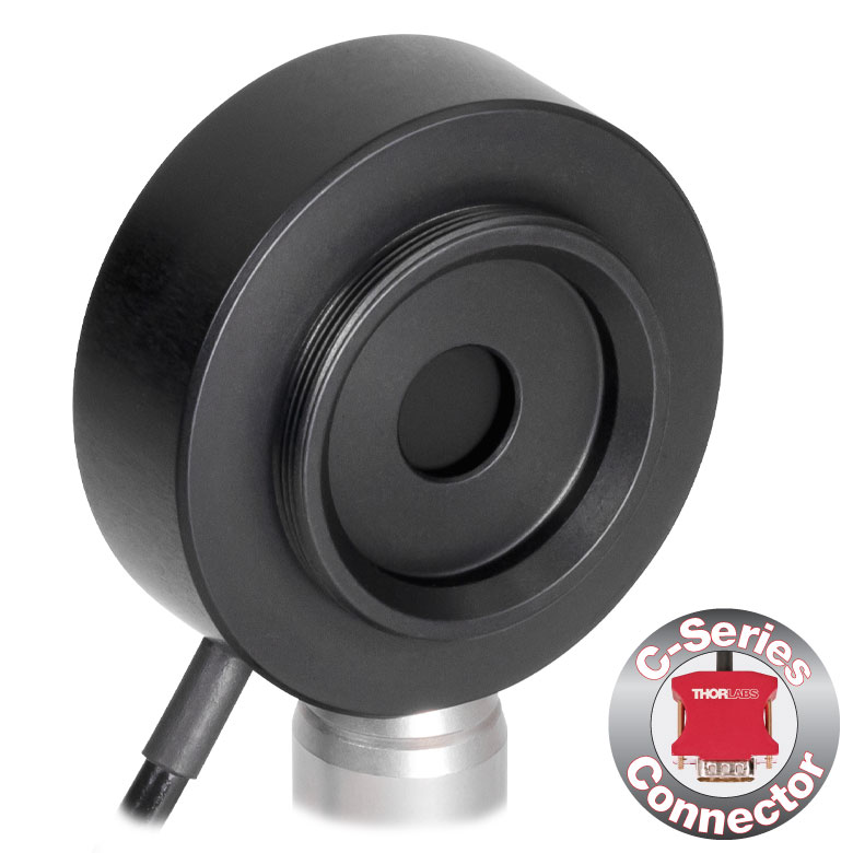 |
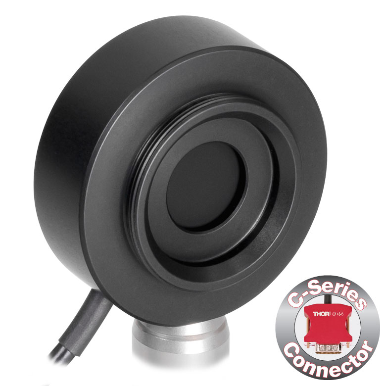 |
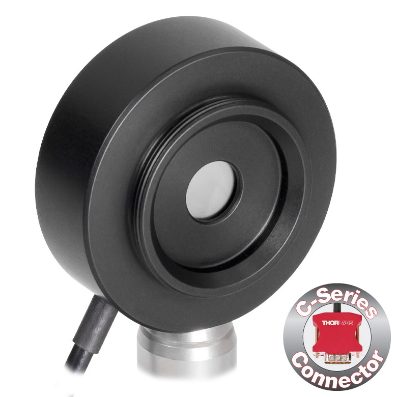 |
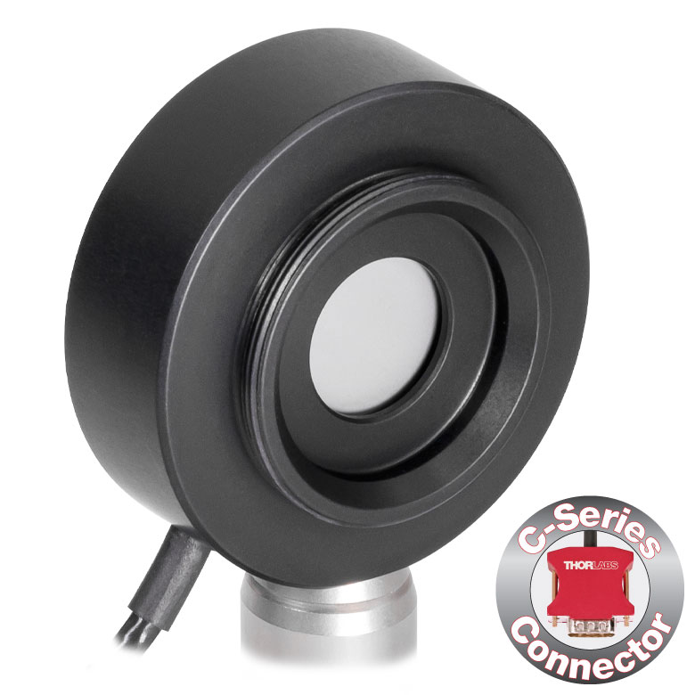 |
| Input Aperture Size | Ø8 mm | Ø12 mm | Ø8 mm | Ø12 mm |
| Wavelength Range | 0.185 - 25 µm | 0.185 - 2.5 µm | ||
| Energy Range | 500 µJ - 1 J | 100 µJ - 1 J | 100 µJ - 1 J | 50 µJ - 500 mJ |
| Max Repetition Rateb | 1 kHz | 250 Hz | 10 kHz | 2 kHz |
| Max Power Density (Pulse Width) |
8 MW/cm2 (10 ns Pulse) |
5 MW/cm2 (10 ns Pulse) |
||
| Max Pulse Energy Density (Pulse Width) |
80 mJ/cm2 (10 ns Pulse) |
50 mJ/cm2 (10 ns Pulse) |
||
| Coating (Click for Plot) | Black Broadband | Metal | ||
| Resolution | 5 µJ | 1 µJ | 1 µJ | 1 µJ |
| Linearity | ±1% | |||
| Measurement Uncertainty | ±5% @ 0.185 - 25 µm | ±5% @ 0.185 - 2.5 µm | ||
| Housing Dimensionsc | Ø38 mm x 15 mm | Ø38 mm x 15 mm | Ø38 mm x 15 mm | Ø38 mm x 15 mm |
| Active Detector Area | 50.3 mm2 | 113.1 mm2 | 50.3 mm2 | 113.1 mm2 |
| Cable Length | 1.5 m (60") | |||
| Post Mounting | 8-32 and M4 Combi Mounting Thread | |||
| Aperture Thread | External SM1 (1.035"-40) Thread Thread Depth: 3.0 mm (0.12") |
|||
| Compatible Consoles | PM400, PM100D, and PM5020 | PM5020 | PM400, PM100D, and PM5020 | |
| Compatible Interfaces | PM103, PM103A, PM103E, PM103U, and PM100USB | PM103, PM103A, PM103E, and PM103U | PM103, PM103A, PM103E, PM103U, and PM100USB | |
| Calibration Service Item # | Compatible Sensors |
|---|---|
| CAL-UVPD | S120VC |
| CAL-PD | S116C, S120C, S121C, S170C, S171C, S140C, S142C, S142CL, S150C, S151C, PM16-120, PM16 |
| CAL-UVPD2 | S130VC |
| CAL-PD2 | S130C, PM16-130, PM160 |
| CAL-NS | NS170C |
| CAL-IRPD | S122C, S144C, S145C, S145CL, S146C, S154C, S155C, PM16-122, PM16-144 |
| CAL-IRPD2 | S132C |
| CAL-MIRPD | S148C, S180C |
Thorlabs offers recalibration services for our photodiode optical power sensors. To ensure accurate measurements, we recommend recalibrating the sensors annually. Recalibration of a single-channel power and/or energy meter console or interface is included with the recalibration of a sensor at no additional cost. If you wish to calibrate one or more sensors with a dual-channel console, each sensor and console calibration service will need to be purchased individually. For more details on these recalibration services, please click the Documents (![]() ) icons below.
) icons below.
Refer to the table to the right for the appropriate calibration service Item # that corresponds to your power sensor.
Requesting a Calibration
Thorlabs provides two options for requesting a calibration:
- Complete the Returns Material Authorization (RMA) form. When completing the RMA form, please enter your name, contact information, the Part #, and the Serial # of each item being returned for calibration; in the Reason for Return field, select "I would like an item to be calibrated." All other fields are optional. Once the form has been submitted, a member of our RMA team will reach out to provide an RMA Number, return instructions, and to verify billing and payment information.
- Select the appropriate sensor calibration Item # below, enter the Part # and Serial # of the sensor that requires recalibration, and then Add to Cart. If you would like a console calibrated with your sensor, repeat this process for Item # CAL-PM1 or CAL-PM2 below, entering the console Item # and Serial #. A member of our RMA team will reach out to coordinate the return of the item(s) for calibration. Note that each console calibration Item # represents the cost of calibrating a console alone; if requesting a single-channel console calibration with a sensor calibration, the appropriate discount will be applied when your request is processed. Should you have other items in your cart, note that the calibration request will be split off from your order for RMA processing.
Please Note: To ensure your item being returned for calibration is routed appropriately once it arrives at our facility, please do not ship it prior to being provided an RMA Number and return instructions by a member of our team.
| Sensor Type | Sensor Item #s |
|---|---|
| Thermal Power | S175C, S302Ca, S305Ca, S310Ca, S314Ca,S322C, S350C, S370C, S401C, S405C, S415C, S425C, S425C-L, S470C, PM160T, PM160T-HP, PM16-401, PM16-405 |
| Pyroelectric Energy | ES111C, ES120C, ES145C, ES220C, ES245C, ES308C, ES312C, ES408C, ES412C |
Thorlabs offers recalibration services for our Thermal Power and Pyroelectric Energy Sensors. To ensure accurate measurements, we recommend recalibrating the sensors annually. Recalibration of a single-channel power and/or energy meter console or interface is included with the recalibration of a sensor at no additional cost. If you wish to calibrate one or more sensors with a dual-channel console, each sensor and console calibration service will need to be purchased individually.
Please note that the CAL-THPY recalibration service cannot be used for our Thermal Position & Power Sensors; recalibration for these sensors can be requested by contacting Tech Support. The table to the upper right lists the sensors for which the CAL-THPY recalibration service is available.
Requesting a Calibration
Thorlabs provides two options for requesting a calibration:
- Complete the Returns Material Authorization (RMA) form. When completing the RMA form, please enter your name, contact information, the Part #s, and the Serial #s of all sensors or consoles being returned for calibration; in the Reason for Return field, select "I would like an item to be calibrated." All other fields are optional. Once the form has been submitted, a member of our RMA team will reach out to provide an RMA Number, return instructions, and to verify billing and payment information.
- Enter the Part # and Serial # of the item that requires recalibration below and then Add to Cart. If you would like a console calibrated with your sensor, repeat this process for Item # CAL-PM1 or CAL-PM2 below, entering the console Item # and Serial #. A member of our RMA team will reach out to coordinate the return of the item(s) for calibration. Note that each console calibration Item # represents the cost of calibrating a console alone; if requesting a single-channel console calibration with a sensor calibration, the appropriate discount will be applied when your request is processed. Should you have other items in your cart, note that the calibration request will be split off from your order for RMA processing.
Please Note: To ensure your item being returned for calibration is routed appropriately once it arrives at our facility, please do not ship it prior to being provided an RMA Number and return instructions by a member of our team. Pyroelectric energy sensors returned for recalibration or servicing must include the separate BNC to DB9 adapter, which contains the sensor EEPROM.
| Calibration Service Item # | Compatible Consoles & Interfaces |
|---|---|
| Single-Channel | |
| CAL-PM1 | PM100D, PM100A, PM400, PM100USB, PM101 Series, PM102 Series, PM103 Series |
| Dual-Channel | |
| CAL-PM2 | PM5020, Previous-Generation PM320E |
These recalibration services are for the power and/or energy meter electronics of our consoles and interfaces. To ensure accurate measurements, we recommend recalibrating annually. Recalibration of a single-channel console or interface is included with these sensor recalibration services at no additional cost. If you wish to calibrate one or more sensors with a dual-channel console, each sensor and console calibration service will need to be purchased individually. For more details on these recalibration services, please click the Documents (![]() ) icons below.
) icons below.
The table to the upper right lists the power and/or energy meter consoles and interfaces that can be calibrated using the CAL-PM1 and CAL-PM2 recalibration services.
Requesting a Calibration
Thorlabs provides two options for requesting a calibration:
- Complete the Returns Material Authorization (RMA) form. When completing the RMA form, please enter your name, contact information, the Part #, and the Serial # of each item being returned for calibration; in the Reason for Return field, select "I would like an item to be calibrated." All other fields are optional. Once the form has been submitted, a member of our RMA team will reach out to provide an RMA Number, return instructions, and to verify billing and payment information.
- Select the appropriate Item # below, enter the Part # and Serial # of the item that requires recalibration, and then Add to Cart. If you would like to calibrate one or more sensors with your console, repeat this process for the appropriate sensor recalibration service above, entering the console Item # and Serial #. A member of our RMA team will reach out to coordinate return of the item(s) for calibration. Note that each console calibration Item # represents the cost of calibrating a console alone; if requesting a single-channel console calibration with a sensor calibration, the appropriate discount will be applied when your request is processed. Should you have other items in your cart, note that the calibration request will be split off from your order for RMA processing.
Please Note: To ensure your item being returned for calibration is routed appropriately once it arrives at our facility, please do not ship it prior to being provided an RMA Number and return instructions by a member of our team.