 Products Home / Optical Elements / Single-Pass and Multipass Cells / Herriott Cells for Multipass Absorption Spectroscopy
Herriott Cells for Multipass Absorption Spectroscopy
- 10.4 m or 31.2 m Optical Path Length in 0.4 m Long Cell
- Mid-Infrared-Enhanced Gold Mirrors & CaF2 Windows
- Angled Entry & Exit Ports for Ease of Alignment
- Interfaces Compatible with Thorlabs' Optomechanics
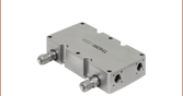
Angled Optical Ports for
FiberPort Collimators,
30 mm Cage System,
or Ø1" Lens Tubes
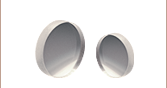
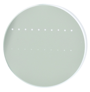
Ø2" Concave Mirrors
with Gold Coating and
Ø3 mm Off-Axis Holes
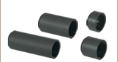
Gas Ports with Swagelok® Tube Fittings
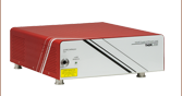
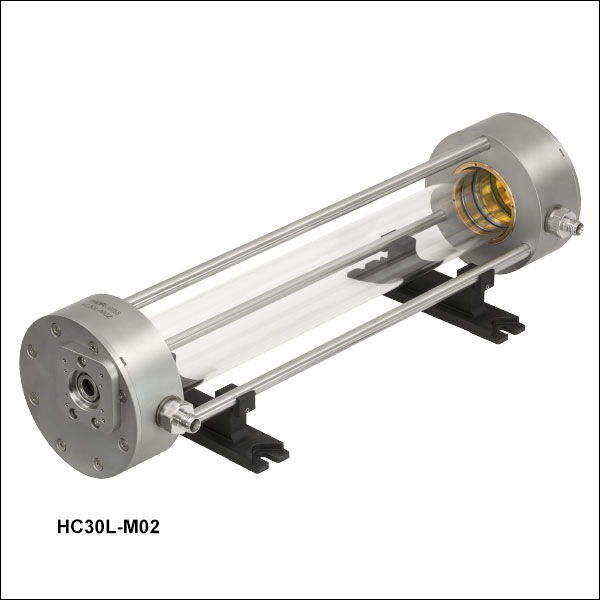
HC30L-M02
31.2 m Herriott Cell with
1/4" OD Tube Fittings
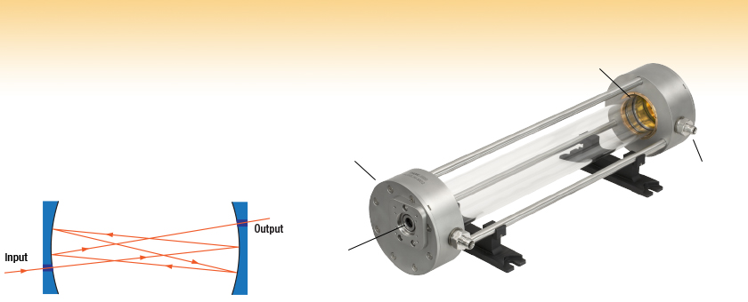
A Herriott cell increases the path length of a beam through the cell.
The HC30L-M02 Herriott Cell has 80 internal reflections.
Ø1/2"
Calcium Fluoride
Wedged Windows


Please Wait
Click to Enlarge
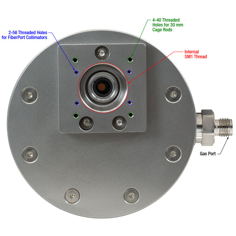
Figure 1.1 The interface on each mounting plate is angled at the necessary beam injection angle for ease of alignment. See the Getting Started tab for details.
Applications
- Absorption Spectroscopy
- Breath or Process Gas Analysis
- Environmental Monitoring
- Medical Diagnostics
- Instrument Calibration
- Combustion Processes
Click to Enlarge
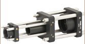
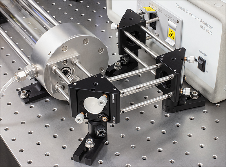
Figure 1.2 Each Herriott cell has angled optical ports that aid alignment into the cell; see the Getting Started tab for details. In this photo, our jointed cage rods and ERSCB-P4 adapters couple the angled output into right-angle kinematic mirror mounts in a table-mounted 30 mm cage system.
Features
- Multipass Herriott-Type Cell Design Increases Absorption in Spectroscopic Measurements
- Ø2" Concave Mirrors Coated with Mid-Infrared Enhanced Gold
- Ø1/2" Calcium Fluoride Parallel Port Wedged Windows (User Replaceable)
- Each Cell is Individually Tested for Pressure and Leakage
- Operating Pressure Range: <10-4 Torr up to 2 atm
- Gas Interface: Ø1/4" or Ø6 mm Swagelok® Tube Fitting
- Gas Leakage Rate: <10-5 Torr·L/s
- Compatible with Thorlabs' FiberPort Collimators, 30 mm Cage System, and Ø1" Lens Tubes
- Contact Tech Support for Custom Units with Other Windows, Mirror Coatings, Gas Ports, or Stainless Steel Cells
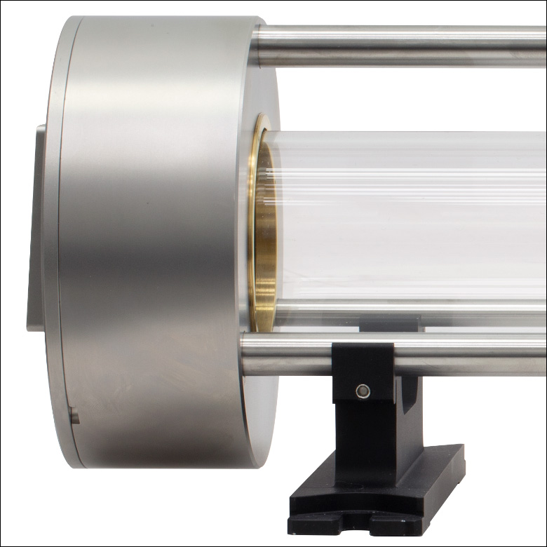
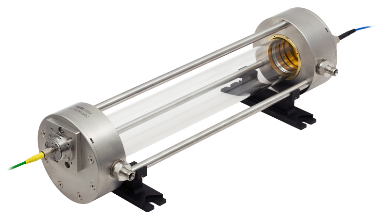
Thorlabs' Herriott cells are compact solutions for achieving long path lengths in gas absorption spectroscopy applications. These Herriott-type multipass cells feature either 10.4 m or 31.2 m optical path lengths and concave mirrors with protected gold coatings designed for enhanced performance in the mid-IR. Each cell provides two gas connection ports for use in either a static pressure configuration or as a flow cell. All Herriott cells are individually vacuum and leak tested to make sure each unit meets specifications. The optical apertures on each end feature mounting plates for a variety of Thorlabs optomechanical standards for ease of alignment. To request a quote for a custom Herriott cell with other windows, mirror coatings, gas ports, or a stainless steel tube instead of a glass tube, please contact Tech Support.
Herriott-Type Multipass Cells
Usually referred to as Herriott cells, these long-optical-path absorption cells are used primarily for weak-trace-gas absorption spectroscopy applications such as environmental monitoring, combustion processes, medical diagnostics, and fundamental atomic and molecular physics. Compared to other long-optical-path absorption cells, such as the White cell, the Herriott cell is more stable to small perturbations. The major advantages of the Herriott cell are that it provides a relatively long absorption path in a compact design and that it is much simpler than high-finesse optical cavities (which would typically require spatial mode matching, precise optical alignment, or resonant excitation). Please refer to the Herriott Cell Mirrors presentation for more details on the principles behind Herriott cells, and see the Applications tab for three application examples. We also offer compact multipass cells with 1 m or 3.2 m optical path lengths.
Gas Interface
Each Herriott cell is equipped with two gas connection ports. If not operated in a flow cell configuration, the second gas port could instead be used to connect a pressure gauge or other similar device to the cell. The gas ports are equipped with standard, male Swagelok® stainless steel tube fittings. Our imperial cells feature a fitting for a 1/4" OD tube while our metric cells feature a fitting for a 6 mm OD tube.
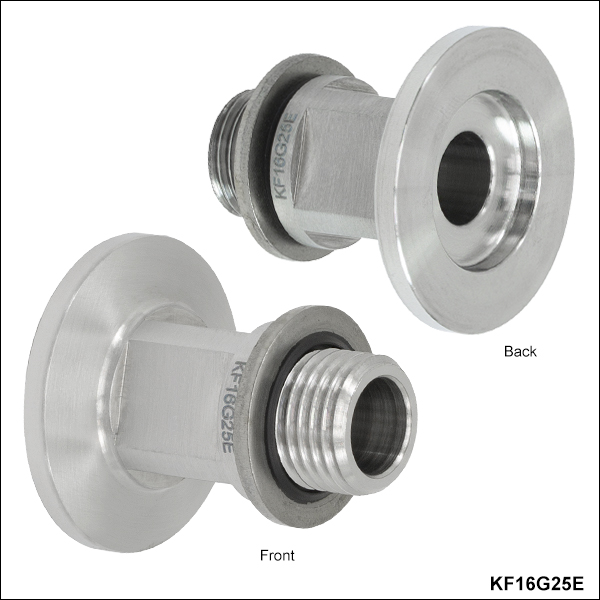
The tube fittings can be disconnected for access to the G1/4" parallel female thread connector in the cell housing. The KF16G25E KF16 Flange Adapter (sold separately below) allows the Herriott Cell to connect to KF16 vacuum components. Additionally, British Standard Parallel Piping (BSPP) pipes may be directly connected to the female thread connector. Note that the leakage rate is not guaranteed if the gas fitting is replaced or adjusted by the end user. If you are unsure how to connect the cell to your existing vacuum or gas supply system, please contact Tech Support.
Angled Optical Ports
This multipass Herriott cell has an aperture on each end with a mounting plate that provides compatibility with Thorlabs' FiberPort Collimators, 30 mm Cage System, and Ø1" Lens Tubes. The surface of each mounting plate is manufactured to be perpendicular to the nominal beam path to simplify alignment; refer to the Specs tab for details. For details on how to take advantage of these mounting features, even when operating the cell with free-space optics not directly attached to the cell, please refer to the Getting Started tab. Note that our 31.2 m cells have been designed such that the optical input on the engraved end is in the plane of the optical table. The other ends of our cells have beam propagation directions with an angular offset in both horizontal and vertical orientations. Please click the Documents (![]() ) icons below for details.
) icons below for details.
| Item # | HC10L-M02 | HC10L/M-M02 | HC30L-M02 | HC30L/M-M02 |
|---|---|---|---|---|
| Optical Specifications | ||||
| Recommended Operating Wavelength |
600 nm to ~10 µma | 1.5 µm to ~10 µma | ||
| Optical Path Length | 10.439 ± 0.015 m | 31.227 ± 0.020 m | ||
| Number of Reflections Inside the Cell |
28 | 80 | ||
| Max Input Beam Diameter (1/e2, Collimated) |
2 mm | 1.3 mm | ||
| Beam Angles of Incidence (Horizontal, Vertical)b |
Engraved End: 3.2° H, 2.8° V | Engraved End: 4.2° H, 0° V | ||
| Unengraved End: 2.5° H, 3.5° V | Unengraved End: 4.1° H, 0.3° V | |||
| Mirrors | CM508-200EH4-M02 Concave Mirrors with Ø4 mm Hole |
CM508-200-M02 Concave Mirrors with Custom Ø3 mm Hole |
||
| Windows | WW50530 Uncoated Calcium Fluoride Wedged Windows | |||
| Gas Specifications | ||||
| Supported Pressurec | <10-4 Torr - 2 atm (1520 Torr) | |||
| Gas Leakage Rated | <10-5 Torr·L/s | |||
| Sample Volume | ≈0.7 L | ≈0.85 L | ||
| Gas Interface | 1/4" OD Tube Swagelok® |
6 mm OD Tube Swagelok® |
1/4" OD Tube Swagelok® |
6 mm OD Tube Swagelok® |
| Fitting Interface in Housing |
G1/4" Straight Thread | |||
| Materials in Contact with Gas Sample |
Stainless Steel (1.4301), Aluminum, Calcium Fluoride, Borosilicate Glass, UV Fused Silica, Gold with Protective Overcoat per MIL-C-48497A, FKM (Viton), Torr Seal® Epoxy |
|||
| General Specifications | ||||
| Bake-Out Temperature | 80 °C Max | |||
| Operating Temperature | -5 to 80 °C (Non-Condensing) | 0 to 40 °C (Non-Condensing) | ||
| Storage Temperature | -20 to 80 °C | |||
| Dimensions (LxWxH) | 16.30" x 6.00" x 4.45" (414.1 mm x 152.0 mm x 113.1 mm) |
437.8 mm x 152.0 mm x 113.1 mm (17.24" x 6.00" x 4.45") |
||
| Mass (Weight) | 5.7 kg (12.6 lbs) | 5.8 kg (12.8 lbs) | ||
- The cell is designed to work interference-free for wavelengths up to 16 µm, but the operating range is limited by the bandwidth of the optics. For wavelengths shorter than 2 µm, please refer to the mirror coating reflectance curve. For wavelengths longer than 10 µm, the calcium fluoride cell windows must be replaced by windows made of an appropriate material, e.g., zinc selenide. For more information, see the Graphs tab, see the Troubleshooting section of the Getting Started tab, or contact Tech Support.
- These angles are specified with parrallel windows and the cell oriented with the engraving pointing upwards. The wedged windows mounted in the cell introduce a small but wavelength-dependent angle pointing away from the center of the cell in the horizontal plane. This angle is approx. 0.2° (or approx. 1 mm over 30 cm) over the specified operating wavelength range. Please click the Documents (
 ) icons below for details.
 - Each unit is tested down to a fraction of a mTorr.
- Specified at a test pressure of 10-3 – 10-2 Torr; not valid for pressure above 760 Torr. Leakage rate is not guaranteed if the gas fitting is replaced or adjusted by the end user.
| Concave Mirror Specifications | ||
|---|---|---|
| Item # | 10.4 m Cells: CM508-200EH4-M02 31.2 m Cells: Custom CM508-200-M02 |
|
| Focal Length | 200.0 mm | |
| Outer Diameter | 2" | |
| Clear Aperture | >Ø45.7 mm | |
| Off-Axis Hole (20.0 mm from Center) |
10.4 m Cells: Ø4.0 mm 31.2 m Cells: Ø3.0 mm |
|
| Coating | Gold with Protective Overcoat per MIL-C-48497A | |
| Reflectance (0° - 45° AOI) | Ravg > 98%, Rabs > 95% from 2.0 - 20.0 µm | |
| Reflectance Plots (Click for Details) |
||
| Damage Threshold |
Pulsed | 0.1 J/cm2 at 1.064 µm, 10 ns, 10 Hz, Ø1.06 mm 3 J/cm2 at 10.6 µm, 100 ns, 1 Hz, Ø1.29 mm |
| CWa | 25 W/cm at 1.07 µm, Ø1.04 mm 450 W/cm at 10.6 µm, Ø1.18 mm |
|
| Surface Quality | 40-20 Scratch-Digb | |
| Power Tolerance | <λ/2 @ 633 nmb | |
| Surface Irregularity | <λ/4 @ 633 nmb | |
| Back Surface Finish | Uniform Fine Grind #12-20 Grit | |
| Substrate | UV Fused Silicac | |
| Window Specifications | ||
|---|---|---|
| Item # | WW50530 | |
| Diameter | 1/2" (12.7 mm) | |
| Diameter Tolerance | +0.0 / -0.2 mm | |
| Thickness | 3.0 mm | |
| Thickness Tolerance | ±0.1 mm | |
| Clear Aperture | ≥Ø11.43 mm | |
| Transmission Plot (Click for Details) |
 Raw Data |
|
| Wedge Angle | 30 arcmin | |
| Wedge Angle Tolerance | ±10 arcmin | |
| Surface Flatnessa | ≤λ/16 Over Central Ø5 mm; ≤λ/8 Full Clear Aperture | |
| Surface Quality | 40-20 Scratch-Dig | |
| Substrate | Calcium Fluorideb | |
Click to Enlarge
Click Here for Raw Data
This graph shows the measured reflectance of our MIR-enhanced-gold-coated mirrors near normal incidence. The shaded region in the graph denotes the range over which we guarantee the specified reflectance. Please note that the reflectance outside of this band is typical and can vary from lot to lot, especially in out-of-band regions where the reflectance is fluctuating or sloped.
Click to Enlarge
Click Here for Raw Data
This graph shows the measured transmission of an uncoated calcium fluoride window at normal incidence.
Click to Enlarge
Click Here for Raw Data
This graph shows simulated throughput for the HC10L(/M)-M02 Herriott cell using measured transmission values for the calcium fluoride windows and measured reflectance values for the MIR-enhanced-gold-coated mirrors. The blue shaded region in the graph denotes the recommended operating wavelength range. The yellow shaded region denotes the extended range which would require replacing the included calcium fluoride cell windows with windows made of an appropriate material, e.g. zinc selenide. For more information, please see the Troubleshooting section of the Getting Started tab, or contact Tech Support.
Click to Enlarge
Click Here for Raw Data
This graph shows simulated throughput for the HC30L(/M)-M02 Herriott cell using measured transmission values for the calcium fluoride windows and measured reflectance values for the MIR-enhanced-gold-coated mirrors. The green shaded region in the graph denotes the extended range with reduced transmission due to the mirror coating. The blue shaded region denotes the recommended operating wavelength range. The yellow shaded region denotes the enhanced range which would require replacing the included calcium fluoride cell windows with windows made of an appropriate material, e.g. zinc selenide. For more information, please see the Troubleshooting section of the Getting Started tab, or contact Tech Support.
Click for Details
Figure 4.2 Each mounting plate has tapped holes for Ø6 mm cage rods, tapped holes for a FiberPort Collimator, and an optical aperture with internal SM1 threads.
Click to Enlarge
Figure 4.1 The mounts are compatible with 1/4"-20 (M6) cap screws and their spacing is adjustable. Each locking setscrew has a 5/64" (2.0 mm) hex.
Getting Started
First place the Herriott cell mounts on an optical table or breadboard. Next, place the Herriott cell on the mounts and make sure that the cell rods snap into the mounts. Adjust the mount spacing to match the hole spacing of your table or breadboard. Secure the cell using the locking setscrews in each mount, shown in Figure 4.1. Then remove the end caps (replacement item # SM1CP2) from each optical port. The cell can be used in either direction, in the sense that there is no designated input or output. Note that to reduce spectroscopic background effects, the cell windows are mounted perpendicular to the common optical axis of the Herriott cell mirrors. This means they are approximately 3° from being perpendicular to the nominal optical beam path (refer to the Specs tab for the angles of incidence).
The angled mounting plates on each end of the cell provide compatibility with Thorlabs' FiberPort Collimators, 30 mm Cage System, and Ø1" Lens Tubes, as illustrated in Figure 4.2. The interface surfaces of the mounting plates are manufactured to be perpendicular to the nominal beam path, simplifying alignment even when operating the cell with free-space optics not directly attached to the cell. See the example in the Free-Space Operation section below for more details.
Each gas port is sealed with an end plug, which must be removed prior to connecting a tube or gas pipe to the port. The plug can be removed using a 9/16" (14 mm) wrench; make sure the gas port adapter is held firmly in the cell housing by using a 1/4" (19 mm) wrench while removing the Swagelok plug. To seal a gas port, leave a plug tightened onto it. Note that the leak test during manufacturing was performed with the plug installed on the port in the unengraved housing and with the port in the engraved housing connected to the vacuum and leak test system.

Click to Enlarge
Figure 4.3 Each mounting plate is angled at the necessary beam insertion angle for ease of alignment. ER10 Cage Rods with CPA1 Alignment Plates are shown.
Alignment
Free-Space Operation
The alignment of an incoming free-space beam can be simplified through the use of cage rods and our alignment tools. For example, connect 30 mm cage assembly rods (e.g. ER10) to the mounting plate and use a cage system target plate (CPA1) as shown in Figure 4.3 (only the upper two rods are necessary in this scenario). Be careful to put the target plate perpendicular to the rods. Note that since these plates are angled, the optical axis of a connected cage system will not be parallel to the table surface. Initial alignment can be achieved by aligning the beam along the optical axis defined by the mounting plate. Please note that the mounting plates have a tolerance of ±0.3° in a system using parallel windows. The wedged windows mounted in the cell cause a small, but wavelength-dependent angle of approximately 0.2 degrees (or about 1 mm over 30 cm) pointing away from the cell center in the horizontal plane is added. We recommend using a 500 mm focal length bi-convex lens prior to the cell (at 500 mm distance from the center of the cell). This ensures that a collimated beam at the cell input does not lead to an overspill of light on the mirrors, causing background signals.
We also recommend the use of two folding mirrors prior to the Herriott cell to position and angle the incident beam. After initial alignment, make sure that the beam is not truncated by the apertures. This can be done by carefully introducing small misalignments to the beam and monitoring the cell transmitted intensity with a large-area photodetector (making sure all transmitted light is being detected); the transmitted power should not change as the small misalignments are introduced.
Please note that truncation of the beam by any element along the path will result in a residual background signal imposed on the spectroscopic signal, reducing the system's overall performance. When operating the cell with invisible laser light, pre-aligning the system with with visible laser light (e.g. in the reverse beam direction) can simplify the alignment of the invisible beam.
Click to Enlarge
Figure 4.4 The mounting plates are also compatible with FiberPort Collimators. Note that the FiberPorts can be prealigned with a visible laser when working with infrared light.
FiberPort Operation
Thorlabs FiberPort Collimators / Couplers can be mounted directly on the mounting plates. Please ensure that the FiberPort used does not have an output 1/e2 waist diameter that is greater than the max beam diameter. For FiberPort operating instructions, please refer to the FiberPort manual. For best performance, the focus of the beam should be moved as far towards the opposing mirror as possible with the particular FiberPort in use. When working with infrared light, note that the FiberPort can be prealigned with a visible laser.
Window Replacement
The pair of WW50530 Uncoated Calcium Fluoride Wedged Windows included with each Herriott cell can be removed and replaced with windows of the same thickness and diameter. Each window is secured with a POLARIS-SM05RR SM05-Threaded Retaining Ring, which can be removed with an SPW603 Spanner Wrench. There is also a Viton O-ring (9.25 mm inner diameter x 1.78 mm thick) between each window and the cell and a Viton X-ring (9.25 mm inner diameter x 1.78 mm thick) between each window and retaining ring. Note that replacing the included wedged windows with flat windows with parallel sides may cause a weak fringing effect. If this a factor limitng the system's overall performance, revert to using wedged windows.
Troubleshooting
It is possible that the spectroscopic signal observed after the multipass cell is deteriorated by fringes. Among other reasons (e.g. standing waves in optical elements before or after the cell, or standing waves between different optical components), this problem can occur when the light beam is truncated. Please ensure that:
- The beam size does not exceed the maximum allowed beam size for the particular cell, and
- The beam enters/leaves the cell through the center of the mirror holes without being cropped.
Herriott Cell Considerations
The Herriott cell can be implemented into optical setups in a wide variety of configurations, both from an optical point of view and a vacuum system point of view. Optically, there are two fundamentally different approaches when using the cell for analytical spectroscopic applications. These approaches differ in how the spectrum is resolved in the system. One of these approaches is to couple in a tunable narrowband light source (most often a laser) into the cell and then use a photodetector on the other side of the cell for analysis. In this case, the light source is the spectrally resolving part; by tuning the frequency of the light source over a spectral feature of the target analyte and by knowing the relevant experimental parameters, quantitative spectroscopy can be performed. The other approach incorporates a broadband source (e.g. Globar, LED, superluminescent source, or a broad linewidth laser) and a spectrally resolving device at the output of the cell, for instance a Fourier-based optical spectrum analyzer, a grating, or a tunable optical filter. It is important in all cases that the system is capable of precisely selecting a target feature at a specific wavelength.
Before a gas sample can be analyzed, it must fill the Herriott cell. A number of parameters must be determined in order to find a system design that meets the requirements imposed by the spectroscopic application. The answers to the following questions will help you decide on the experimental setup:
- Can the experiment be run by evacuating the cell and subsequently filling it with the analyte under investigation (static pressure experiment) or is there a need of a continuous flow of the analyte through the cell for uninterrupted monitoring of the target feature (flow cell configuration)?
- What time resolution is needed? For static pressure measurements, this requires an answer to the questions of whether and how fast a background signal must be acquired; for flow cell experiments, one needs to decide what flow rate is required to ensure a gas exchange inside the cell fast enough to reach the time resolution needed for the experiment.
- What is the optimal pressure for the experiment? Can the cell be used at atmospheric pressure or does the experiment require sub-atmospheric pressures for optimal detection conditions considering absorption features are likely to interfere at atmospheric pressure conditions.
- Does the sample require preparation before being directed into the Herriott cell? This might for instance involve the removal of water, oil, or solid particles (e.g. dust or soot) from the sample to prevent interference with the target feature or contamination of the cell.
Example Applications
The three sample configurations include either a pressure gauge, a mass flow controller, or both. Additional valves may be useful for improved control over the pressure or flow rate.
Click to Enlarge
Figure 5.1 Flow Cell Configuration at Atmospheric Pressure
Example 1: Flow Cell Configuration at Atmospheric Pressure
This setup for a typical flow cell configuration at atmospheric pressure is illustrated in Figure 5.1. One or more samples are connected to a mass flow controller installed in-line between the cell and the sample (a gas cylinder, pipeline, etc.). The mass flow controller allows the mass flow rate through the cell to be set accurately. For less demanding experiments, the mass flow controller can be replaced by needle valves for less robust control of the flow rate.
Example 2: Flow Cell Configuration at Sub-Atmospheric Pressure
In this example, a gas sample passes a needle valve before it enters the cell. The cell output is evacuated by a pump where the pumping speed can be adjusted with another needle valve between the cell output and the pump. Balancing the two needle valves allows for adjustment of both pressure and mass flow rate through the cell. For a true reading of the pressure inside the cell it is important to install the pressure gauge between the two needle valves. An optional mass flow meter in-line with the gas flow (as illustrated in Figure 5.2) provides a reading of the mass flow through the cell.
Example 3: Steady State Sub-Atmospheric Pressure Experiment
This setup for a typical steady state experiment at sub-atmospheric pressures is illustrated in Figure 5.3. Before a sample is directed into the Herriott cell, the cell is evacuated by a pump system, e.g. by a turbomolecular pump backed by a fore-vacuum (backing) pump. A pressure gauge connected to the cell allows the user to measure the pressure present inside the cell. Once the cell is evacuated, the pump is disconnected by closing the valve next to the pump system. Carefully opening the valve closest to the sample container (e.g. a gas cylinder or Tedlar bags containing either human breath or other gases collected at a remote test site) allows the cell to be filled with the sample; once the desired end pressure is reached, the inlet valve is closed and a measurement can be executed.

Click to Enlarge
Figure 5.2 Flow Cell Configuration at Sub-Atmospheric Pressure
Click to Enlarge
Figure 5.3 Steady State Sub-Atmospheric Pressure Experiment
| Table 6.1 Damage Threshold Specifications | ||
|---|---|---|
| Coating Designation (Item # Suffix) |
Damage Threshold | |
| -M02 | Pulsed | 0.1 J/cm2 at 1.064 µm, 10 ns, 10 Hz, Ø1.06 mm 3 J/cm2 at 10.6 µm, 100 ns, 1 Hz, Ø1.29 mm |
| CWa | 25 W/cm at 1.07 µm, Ø1.04 mm 450 W/cm at 10.6 µm, Ø1.18 mm |
|
Damage Threshold Data for Thorlabs' Mid-Infrared Enhanced Mirrors
The specifications in Table 6.1 are measured data for Thorlabs' mid-infrared enhanced gold mirror coatings. Damage threshold specifications are constant for a given coating type, regardless of the size or shape of the mirror.
Laser Induced Damage Threshold Tutorial
The following is a general overview of how laser induced damage thresholds are measured and how the values may be utilized in determining the appropriateness of an optic for a given application. When choosing optics, it is important to understand the Laser Induced Damage Threshold (LIDT) of the optics being used. The LIDT for an optic greatly depends on the type of laser you are using. Continuous wave (CW) lasers typically cause damage from thermal effects (absorption either in the coating or in the substrate). Pulsed lasers, on the other hand, often strip electrons from the lattice structure of an optic before causing thermal damage. Note that the guideline presented here assumes room temperature operation and optics in new condition (i.e., within scratch-dig spec, surface free of contamination, etc.). Because dust or other particles on the surface of an optic can cause damage at lower thresholds, we recommend keeping surfaces clean and free of debris. For more information on cleaning optics, please see our Optics Cleaning tutorial.
Testing Method
Thorlabs' LIDT testing is done in compliance with ISO/DIS 11254 and ISO 21254 specifications.
First, a low-power/energy beam is directed to the optic under test. The optic is exposed in 10 locations to this laser beam for 30 seconds (CW) or for a number of pulses (pulse repetition frequency specified). After exposure, the optic is examined by a microscope (~100X magnification) for any visible damage. The number of locations that are damaged at a particular power/energy level is recorded. Next, the power/energy is either increased or decreased and the optic is exposed at 10 new locations. This process is repeated until damage is observed. The damage threshold is then assigned to be the highest power/energy that the optic can withstand without causing damage. A histogram such as that below represents the testing of one BB1-E02 mirror.
The photograph above is a protected aluminum-coated mirror after LIDT testing. In this particular test, it handled 0.43 J/cm2 (1064 nm, 10 ns pulse, 10 Hz, Ø1.000 mm) before damage.
| Example Test Data | |||
|---|---|---|---|
| Fluence | # of Tested Locations | Locations with Damage | Locations Without Damage |
| 1.50 J/cm2 | 10 | 0 | 10 |
| 1.75 J/cm2 | 10 | 0 | 10 |
| 2.00 J/cm2 | 10 | 0 | 10 |
| 2.25 J/cm2 | 10 | 1 | 9 |
| 3.00 J/cm2 | 10 | 1 | 9 |
| 5.00 J/cm2 | 10 | 9 | 1 |
According to the test, the damage threshold of the mirror was 2.00 J/cm2 (532 nm, 10 ns pulse, 10 Hz, Ø0.803 mm). Please keep in mind that these tests are performed on clean optics, as dirt and contamination can significantly lower the damage threshold of a component. While the test results are only representative of one coating run, Thorlabs specifies damage threshold values that account for coating variances.
Continuous Wave and Long-Pulse Lasers
When an optic is damaged by a continuous wave (CW) laser, it is usually due to the melting of the surface as a result of absorbing the laser's energy or damage to the optical coating (antireflection) [1]. Pulsed lasers with pulse lengths longer than 1 µs can be treated as CW lasers for LIDT discussions.
When pulse lengths are between 1 ns and 1 µs, laser-induced damage can occur either because of absorption or a dielectric breakdown (therefore, a user must check both CW and pulsed LIDT). Absorption is either due to an intrinsic property of the optic or due to surface irregularities; thus LIDT values are only valid for optics meeting or exceeding the surface quality specifications given by a manufacturer. While many optics can handle high power CW lasers, cemented (e.g., achromatic doublets) or highly absorptive (e.g., ND filters) optics tend to have lower CW damage thresholds. These lower thresholds are due to absorption or scattering in the cement or metal coating.
LIDT in linear power density vs. pulse length and spot size. For long pulses to CW, linear power density becomes a constant with spot size. This graph was obtained from [1].
Pulsed lasers with high pulse repetition frequencies (PRF) may behave similarly to CW beams. Unfortunately, this is highly dependent on factors such as absorption and thermal diffusivity, so there is no reliable method for determining when a high PRF laser will damage an optic due to thermal effects. For beams with a high PRF both the average and peak powers must be compared to the equivalent CW power. Additionally, for highly transparent materials, there is little to no drop in the LIDT with increasing PRF.
In order to use the specified CW damage threshold of an optic, it is necessary to know the following:
- Wavelength of your laser
- Beam diameter of your beam (1/e2)
- Approximate intensity profile of your beam (e.g., Gaussian)
- Linear power density of your beam (total power divided by 1/e2 beam diameter)
Thorlabs expresses LIDT for CW lasers as a linear power density measured in W/cm. In this regime, the LIDT given as a linear power density can be applied to any beam diameter; one does not need to compute an adjusted LIDT to adjust for changes in spot size, as demonstrated by the graph to the right. Average linear power density can be calculated using the equation below.

The calculation above assumes a uniform beam intensity profile. You must now consider hotspots in the beam or other non-uniform intensity profiles and roughly calculate a maximum power density. For reference, a Gaussian beam typically has a maximum power density that is twice that of the uniform beam (see lower right).
Now compare the maximum power density to that which is specified as the LIDT for the optic. If the optic was tested at a wavelength other than your operating wavelength, the damage threshold must be scaled appropriately. A good rule of thumb is that the damage threshold has a linear relationship with wavelength such that as you move to shorter wavelengths, the damage threshold decreases (i.e., a LIDT of 10 W/cm at 1310 nm scales to 5 W/cm at 655 nm):

While this rule of thumb provides a general trend, it is not a quantitative analysis of LIDT vs wavelength. In CW applications, for instance, damage scales more strongly with absorption in the coating and substrate, which does not necessarily scale well with wavelength. While the above procedure provides a good rule of thumb for LIDT values, please contact Tech Support if your wavelength is different from the specified LIDT wavelength. If your power density is less than the adjusted LIDT of the optic, then the optic should work for your application.
Please note that we have a buffer built in between the specified damage thresholds online and the tests which we have done, which accommodates variation between batches. Upon request, we can provide individual test information and a testing certificate. The damage analysis will be carried out on a similar optic (customer's optic will not be damaged). Testing may result in additional costs or lead times. Contact Tech Support for more information.
Pulsed Lasers
As previously stated, pulsed lasers typically induce a different type of damage to the optic than CW lasers. Pulsed lasers often do not heat the optic enough to damage it; instead, pulsed lasers produce strong electric fields capable of inducing dielectric breakdown in the material. Unfortunately, it can be very difficult to compare the LIDT specification of an optic to your laser. There are multiple regimes in which a pulsed laser can damage an optic and this is based on the laser's pulse length. The highlighted columns in the table below outline the relevant pulse lengths for our specified LIDT values.
Pulses shorter than 10-9 s cannot be compared to our specified LIDT values with much reliability. In this ultra-short-pulse regime various mechanics, such as multiphoton-avalanche ionization, take over as the predominate damage mechanism [2]. In contrast, pulses between 10-7 s and 10-4 s may cause damage to an optic either because of dielectric breakdown or thermal effects. This means that both CW and pulsed damage thresholds must be compared to the laser beam to determine whether the optic is suitable for your application.
| Pulse Duration | t < 10-9 s | 10-9 < t < 10-7 s | 10-7 < t < 10-4 s | t > 10-4 s |
|---|---|---|---|---|
| Damage Mechanism | Avalanche Ionization | Dielectric Breakdown | Dielectric Breakdown or Thermal | Thermal |
| Relevant Damage Specification | No Comparison (See Above) | Pulsed | Pulsed and CW | CW |
When comparing an LIDT specified for a pulsed laser to your laser, it is essential to know the following:
LIDT in energy density vs. pulse length and spot size. For short pulses, energy density becomes a constant with spot size. This graph was obtained from [1].
- Wavelength of your laser
- Energy density of your beam (total energy divided by 1/e2 area)
- Pulse length of your laser
- Pulse repetition frequency (prf) of your laser
- Beam diameter of your laser (1/e2 )
- Approximate intensity profile of your beam (e.g., Gaussian)
The energy density of your beam should be calculated in terms of J/cm2. The graph to the right shows why expressing the LIDT as an energy density provides the best metric for short pulse sources. In this regime, the LIDT given as an energy density can be applied to any beam diameter; one does not need to compute an adjusted LIDT to adjust for changes in spot size. This calculation assumes a uniform beam intensity profile. You must now adjust this energy density to account for hotspots or other nonuniform intensity profiles and roughly calculate a maximum energy density. For reference a Gaussian beam typically has a maximum energy density that is twice that of the 1/e2 beam.
Now compare the maximum energy density to that which is specified as the LIDT for the optic. If the optic was tested at a wavelength other than your operating wavelength, the damage threshold must be scaled appropriately [3]. A good rule of thumb is that the damage threshold has an inverse square root relationship with wavelength such that as you move to shorter wavelengths, the damage threshold decreases (i.e., a LIDT of 1 J/cm2 at 1064 nm scales to 0.7 J/cm2 at 532 nm):

You now have a wavelength-adjusted energy density, which you will use in the following step.
Beam diameter is also important to know when comparing damage thresholds. While the LIDT, when expressed in units of J/cm², scales independently of spot size; large beam sizes are more likely to illuminate a larger number of defects which can lead to greater variances in the LIDT [4]. For data presented here, a <1 mm beam size was used to measure the LIDT. For beams sizes greater than 5 mm, the LIDT (J/cm2) will not scale independently of beam diameter due to the larger size beam exposing more defects.
The pulse length must now be compensated for. The longer the pulse duration, the more energy the optic can handle. For pulse widths between 1 - 100 ns, an approximation is as follows:

Use this formula to calculate the Adjusted LIDT for an optic based on your pulse length. If your maximum energy density is less than this adjusted LIDT maximum energy density, then the optic should be suitable for your application. Keep in mind that this calculation is only used for pulses between 10-9 s and 10-7 s. For pulses between 10-7 s and 10-4 s, the CW LIDT must also be checked before deeming the optic appropriate for your application.
Please note that we have a buffer built in between the specified damage thresholds online and the tests which we have done, which accommodates variation between batches. Upon request, we can provide individual test information and a testing certificate. Contact Tech Support for more information.
[1] R. M. Wood, Optics and Laser Tech. 29, 517 (1998).
[2] Roger M. Wood, Laser-Induced Damage of Optical Materials (Institute of Physics Publishing, Philadelphia, PA, 2003).
[3] C. W. Carr et al., Phys. Rev. Lett. 91, 127402 (2003).
[4] N. Bloembergen, Appl. Opt. 12, 661 (1973).
| Posted Comments: | |
Yoon-Soo Jang
(posted 2025-02-12 13:58:05.967) We have HC10L/M and could it remove glass tube?
I want to multipass beam path at ambient air, not at chamber. acanales
(posted 2025-02-13 07:27:53.0) Thank you for your request! It sounds very interesting, so I have contacted you directly to discuss it. Piotr Piotrowiak
(posted 2025-01-15 10:42:34.74) Greetings,
We have been using the HC10L for a couple of months and it is a great product but I have a technical question:
In your description, you mention that in order to control beam blooming, one may position a mildly focusing lens before the cell.
We see the opposite behavior. instead of blooming (diverging), the beam (originally 2 mm) exits the cell focused and converging, i.e. the net effect of the cell is that of a positive lens. We confirmed the correct alignment and the number of passes by measuring the delay time.
Do you suggest that we correct this before or after the cell?
I am thinking of putting a CaF2 Galilean beam expander after the cell and adjust the spacing between the positive and negative lenses of the expander so that the end effect is a wider and nearly collimated beam.
I am open to your suggestions.
Best
Piotr Tobias Baselt
(posted 2023-09-27 07:33:00.123) Dear ladies and gentlemen,
it is possible to operate the Herriott Cells also under 3 bar or 6 bar hydrogen atmosphere. What would have to be taken into account?
Thank you very much and kind regards
Tobias Baselt mkarlsson
(posted 2023-09-28 09:19:01.0) Dear Tobias, thank you for your question! The Herriot Cells are not designed to be used at those pressures and you would likely experience leakage. I’ve reached out to you directly to discuss your application and se if we can provide any solutions. Stephan Schiller
(posted 2021-01-07 15:57:48.633) Please contact me for a specific question YLohia
(posted 2021-01-08 09:37:22.0) Hello, your local Thorlabs Tech Support team can be contacted at europe@thorlabs.com or +49 (0) 8131-5956-2. We will reach out to you directly. V Ebert
(posted 2019-07-19 10:20:57.617) i need to know how i can clean the cell and how i can replace components
is it possible to get a pdf of the manual ?
we want to use it in corrosive applications will the mirrors withstand 100 ppm Hcl in N2
i want to have other pathlengths than 10 m ..
can i align it myself ? can i get it aligned to different pathlength ?
how accurate will you tell the pathlength
can i get a 17025 certification on the path length of the individual cell i buy ?
thanks for your help
best regards Volker Ebert YLohia
(posted 2019-08-14 09:22:47.0) Hello Volker, thank you for contacting Thorlabs. Currently, we do not have a PDF version of the manual. We refer to the information presented on the web page for most of our optics. The cell is not intended to be aligned by the end-user. The item cannot be aligned to a different path length either. The OPL is 10.498 ± 0.020 m. The OPL tolerances are predominantly governed by the tolerances in mirror radius of curvature and factory alignment. Unfortunately, we do not have an ISO 17025 certificate for our Herriott cells. We have reached out to you directly to discuss this further and determine the feasibility of using this in corrosive applications. |

 Zoom
Zoom| Key Specsa | |||||||
|---|---|---|---|---|---|---|---|
| Item # | Operating Wavelength |
Optical Path Length (OPL) |
Internal Reflections |
Max Beam Diameter (1/e2) |
Sample Volume |
Swagelok® Gas Interface | Operating Temperature (Non-Condensing) |
| HC10L-M02 | 600 nm to ~10 µmb |
10.439 ± 0.015 m | 28 | 2 mm | ≈0.7 L | 1/4" OD Tube Fittings | -5 to 80 °C |
| HC10L/M-M02 | 6 mm OD Tube Fittings | ||||||
| HC30L-M02 | 1.5 µm to ~10 µmb |
31.227 ± 0.020 m | 80 | 1.3 mm | ≈0.85 L | 1/4" OD Tube Fittings | 0 to 40 °C |
| HC30L/M-M02 | 6 mm OD Tube Fittings | ||||||

 Zoom
Zoom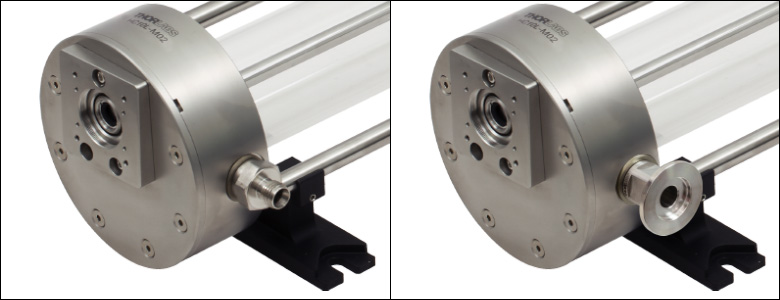
Click to Enlarge
Figure G2.1 The double ferrule fitting on Thorlabs' Herriott cells (left) can be replaced with the KF16G25E vacuum flange adapter (right). The leakage rate is not guaranteed if the user adjusts or replaces the gas fitting.
- Connect KF-Compatible Vacuum Systems to Our Herriott Cells
- British Standard Pipe Parallel (BSPP) Thread
- 304 Stainless Steel Construction for High Durability and Low Outgassing
- External Flats Accept 14 mm (9/16") Wrench
The KF16G25E adapter allows components with G1/4" BSPP internal threading, such as our Herriott cells, to be connected to KF16 flange vacuum systems. This adapter can be installed in the internal G1/4" thread of each cell's gas ports (as shown in Figure G2.1), which are accessed by disconnecting the pre-installed Swagelok® stainless steel tube fittings.
The interior diameter of this adapter is Ø9.0 mm (Ø0.35"). The included rubber gasket is pre-installed onto the part; removing the gasket is not recommended, as it may become damaged. The exterior flats for tightening accept a 14 mm (9/16") wrench. Each flange is shipped with a protective plastic cover.
Note that the leakage rate of our Herriott cells is not guaranteed if the gas fitting is replaced or adjusted by the end user. If you are unsure how to connect the cell to your existing vacuum or gas supply system, please contact Tech Support.