Saturated Absorption Spectroscopy Systems
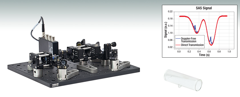
- Ideal for Laser Locking or Teaching Labs
- Rubidium or Potassium Vapor Cells Available Separately
SKSAS
(Breadboard Sold Separately)
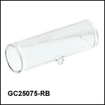
GC25075-RB
Rubidium Vapor Cell
See the SA Spectroscopy Tab for Measurement Details

Please Wait
| Spectroscopy Systems Selection Guide |
|---|
| Dichroic Atomic Vapor Spectroscopy (DAVS) Systems |
| Saturated Absorption Spectroscopy (SAS) Systems |
| Specifications | |
|---|---|
| Required Input Power | ~500 µW |
| Input Fiber Termination* | FC/PC |
| Detector Bandwidth | 1 MHz |
| Detector Output Range | ±10 V |
| Reference Cell Temperature (Max.) | 50 °C |
* Alternate fiber inputs are available. Please contact techsupport@thorlabs.com.
Features
- Saturated Absorption Spectroscopy for Locking to Atomic Transitions
- Rubidium or Custom Vapor Cell Options
- PM Fiber-Coupled Setup
- Ideal for Laser Locking or Teaching Labs
The Thorlabs SKSAS kit offers a proven set of components to construct a compact, fiber-coupled Saturated Absorption Spectroscopy (SAS) setup. It offers a method for producing a highly stable tunable laser locking reference at the peak of atomic hyperfine structure transitions. The kit also allows for the study of the hyperfine structure and Doppler broadening of atomic transitions.
The kit has been designed using stock optics and mechanics, as well as compatible custom components. This makes these kits adaptable using other Thorlabs cage system and lens tube components. For a list of the components and subsystems included in the SAS kit, please see the Kit Contents tab.
While the vapor cell heater is included in the kit, please note that the vapor cell and temperature controller must be purchased separately. Currently, we offer rubidium and potassium reference vapor cells, which are available below. A variety of custom vapor cells are also available; please contact techsupport@thorlabs.com for more details. Thorlabs' TC300B Heater and TEC Temperature Controller is compatible with the cell heater included in each kit. We also offer pre-assembled Herriott cells for gas absorption spectroscopy applications.
Saturated Absorption Spectroscopy
Saturated Absorption Spectroscopy (SAS) systems provide a means to create a highly sensitive lock tied directly to an atomic transition. When an atom absorbs (or emits) a photon, the absorption (or emission) frequency is Doppler shifted. To create a more narrow laser lock, Doppler Broadening is eliminated by use of the well-known saturated absorption technique that resolves the hyperfine structure of atomic transitions. For a detailed tutorial on SAS, please see the SA Spectroscopy tab.
Custom Options
Our spectroscopy kits are adaptable to most tunable lasers with user-supplied feedback mechanisms. While our standard kit is designed to accept PM fiber-coupled sources, we can also offer kits for free-space input. To discuss custom options, please contact us at techsupport@thorlabs.com.
SAS Kit Contents
Thorlabs' SAS Kits contain the following subsystems (breadboard is sold separately):
- Fiber Input and Half-Wave Plate
- Input Prism Assembly
- Vapor Cell and Heater
- Output Prism Assembly
- Pump Mirrors, Folding Mirrors, and Balanced Detector
The complete setup can fit on a single breadboard, either a 10" x 12" breadboard for imperial setups (Item # MB1012) or a 250 mm x 300 mm breadboard for metric setups (Item # MB2530/M), each sold separately. A complete list of all components can be found in Table 2.1.
| Table 2.1 SKSAS(/M) Kit Components |
|---|
Fiber Input and Half-Wave Plate
The fiber input is designed with our F220FC-780 fiber collimator and cage system components. The collimator collimates the input from an FC/PC-terminated PM fiber, which must be purchased separately. For Rubidium, we recommend using our P1-780PM-FC-5 patch cable. For users who would prefer a free-space input, please contact us at techsupport@thorlabs.com for a quote for a kit without the fiber collimator and mounting mechanics.
Once the input is collimated, the light passes through a WPMH05M-780 half-wave plate. The wave plate allows the user to vary the relative intensity of the pump and probe beams, which is helpful during alignment of the kit.
Input Prism Assembly
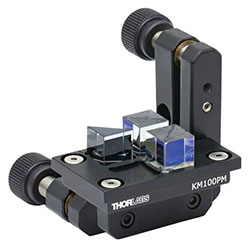
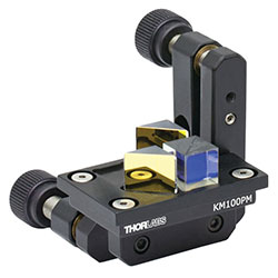
The input prism assembly is constructed on a KM100PM kinematic mount using a specially-designed mounting platform accessory. Three prisms are then epoxied into place on the mounting platform: a MRA10-M01 right-angle prism mirror, a BS011 50:50 non-polarizing beamsplitter, and a PBS102 polarizing beamsplitter.
The polarizing beamsplitter divides the input into the pump and probe beams. The power into each beam can be adjusted using the half-wave plate (part of the fiber input assembly described above). The 50:50 non-polarizing beamsplitter picks off a portion of the input for a reference beam that measures the direct Doppler-broadened absorption spectrum.
Vapor Cell Heater Assembly
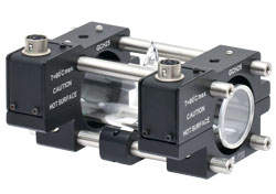
The GCH25-75 heater assembly is provided with the kit and is designed to hold Ø9 mm, Ø19 mm, or Ø25 mm vapor cells 75 mm in length. Please note that neither vapor cells nor a temperature controller for the GCH25-75 are included with the SKSAS. Rubidium and Potassium cells are available on the bottom of this page, and other atomic vapor cells are available upon request. The TC300B Heater and TEC Temperature Controller is compatible with the vapor cell heater included in each kit.
Output Prism Assembly
The output prism assembly is constructed similarly to the input prism assembly, using a custom mounting platform attached to a KM100PM. Three prisms are epoxied to the platform: two MRA10-M01 right-angle prism mirrors, and a PBS102 polarizing beamsplitter.
The polarizing beamsplitter reflects the pump beam to counterpropagate with the probe beam through the cell. The two right-angle mirror prisms are designed to reflect the probe and reference beams so that they may be detected using the balanced detector. A diagram showing the beam path through the system is shown in the "Pump Mirrors, Folding Mirrors, and Balanced Detector" section below.
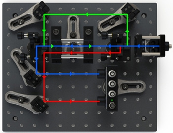 Figure 2.2 SAS System Beam Path
Pump Mirrors, Folding Mirrors, and Balanced Detector
In addition to the input and output prism assemblies, there are four PF05-03-M01 Ø1/2" gold mirrors that are mounted in KS05 mounts. Two of these mirrors are used to direct the pump beam so that it can counterpropagate with the probe beam and thus create the SAS Doppler-free spectrum. The other two mirrors are for directing the probe and reference beams onto the two photodiodes of the balanced detector. A beam path diagram is shown in Figure 2.2, which details the function of these four mirrors.
The PDB210A Balanced Detector provides three output signals: two are the signals from each photodiode, and the third is the difference between these two signals. The voltages from each detector are useful when aligning the system and to investigate the features of the spectra in teaching labs, while the difference signal is useful for laser locking.
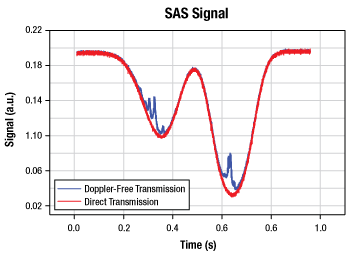
Figure 3.1 The Rubidium D2 absorption spectrum (red) and saturated absorption, or Doppler-Free, spectrum (blue).
Saturated Absorption Spectroscopy
Saturated Absorption Spectroscopy Basics
Every atom has a unique set of absorption frequencies determined by the hyperfine structure of the electronic states. If the atoms are at rest, as light is propagated through the system, light is only absorbed at these discrete transition frequencies, f0. At a given temperature, however, the atoms may be moving according to the Maxwell-Boltzmann temperature distribution of velocities. Because of this distribution, some atoms will be stationary, while others will be moving with various speeds along the direction of light propagation. For laser light at one of the hyperfine transition peaks, f0, the only atoms that will interact are those that are stationary. Atoms at a speed v can only interact with a laser of frequency f (offset from the transition frequencies) which satisfies a Doppler shift to a transition frequency f0. The result for rubidium is a frequency distribution of absorption as shown by the red line in Figure 3.1.
Counter-Propagating Beams
One can imagine having two counter-propagating laser beams traveling through the vapor cell. The light beam at a frequency less than f0 propagating to the left (right) can only interact with a group of atoms moving to the right (left). For a laser frequency greater than f0, the light can only interact with atoms moving in the same direction as the beam's propagation. For a particular laser frequency, each beam interacts with a different group of atoms with a different velocity.
When the laser has a frequency of f0, however, both counter-propagating beams can only interact with atoms that are at rest. Therefore, there will be a depletion of zero-velocity ground state atoms, which will be evidenced by dips in the Doppler-broadened absorption profile, which can be seen in the blue line in Figure 3.1. These dips create very narrow peaks which can be used as a frequency locking point for a tunable laser.
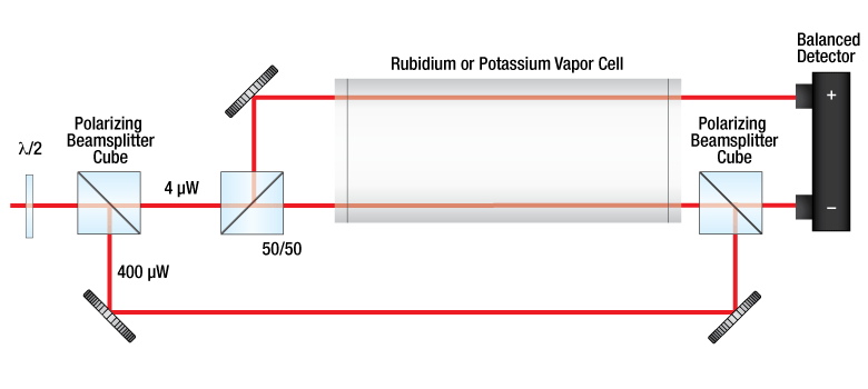
Figure 3.2 Schematic diagram of the SAS system.
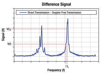
Figure 3.3 Measurement signal from a balanced detector, showing the difference between the direct absorption and the Doppler-free absorption spectra.
The SAS System
A schematic of Thorlabs' SAS system is shown in Figure 3.2. Light passes through a half-wave plate to appropriately set the polarization for the polarizing beamsplitter cube, which passes 4 µW and reflects 400 µW. The 4 µW beam travels through the cell and passes through the second polarizing beamsplitter, and is detected by one port of the balanced detector. This beam is called the probe beam. The 400 µW beam is redirected by two mirrors to be reflected by the second polarizing beamsplitter, and travels the cell in the opposite direction of the probe beam; this is called the pump beam. These counter-propagating pump and probe beams create the on-resonance ground state depletion described above.
A third reference beam is directed from the reflection of the 50/50 beamsplitter, through the vapor cell, and to the second port of the balanced detector. By taking the difference of the reference port (direct transmission) and the probe beam (Doppler-free transmission) signals from the balanced detector, a signal like the one in Figure 3.3 is recorded. This signal removes the Doppler-broadening to reveal several narrow peaks. To use these signals for laser frequency stabilization, the laser is locked to a frequency corresponding to the sharp edge of a transition peak. There is a voltage V(f0) corresponding to this locking frequency. As the laser frequency drifts, the voltage of the difference signal will be different, indicated by V(f) on Figure 3.3. An error signal, calculated by Error(f) = V(f0) = V(f), can then be used by a feedback loop to adjust the lasing frequency until Error(f) = 0. In this manner, the laser frequency can be locked to the transition.
| Posted Comments: | |
Joey B.
(posted 2024-09-02 03:16:43.11) Greetings,
I have a more general question about this kit, I was just wondering if you guys have had anyone modify this set up to make an atomic clock.
If so, could you advise me on how would i go about doing this (thorlab parts and all)?
Thanks, jpolaris
(posted 2024-09-11 01:26:14.0) Thank you for contacting Thorlabs. Our Saturated Absorption Spectroscopy system (SKSAS) is quite far from what is needed to build an atomic clock. Our Dichroic Atomic Vapor Spectroscopy kit (SKDAV) may be somewhat closer to what is needed, since I believe magnetization of the atoms is required in an atomic clock. I have reached out to you directly to discuss further. Min-Kyo Seo
(posted 2024-01-16 11:24:13.837) The SKSAS/M kit does not seem to include a tunable laser. In addition, the TLK-L780M tunable laser kit, suggested in the manual, is not continued in stock. I wonder whether tunable laser kits compatible to SKSAM/M with Rb cell exist in the Thorlabs stock. jdelia
(posted 2024-01-23 08:08:43.0) Thank you for contacting Thorlabs. We unfortunately do not offer anything comparable to the formerly offered tunable laser kits. We will reach out to discuss options for your application. user
(posted 2019-11-07 16:26:30.673) It's great that you have these tutorials. However, the font sizes are too small.
Please consider increasing your font sizes on your websites overall and especially on the tutorial pages.
Moreover, why not provide these tutorial pages in pdf documents. tcampbell
(posted 2019-11-15 03:43:09.0) Hello, thank you for contacting Thorlabs. You can enlarge the display on most Internet browsers by pressing CTRL and + or by holding CTRL and using the scroll wheel on your mouse. |

Click to Enlarge
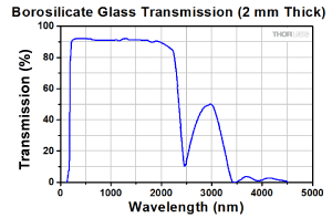
Figure 365A Borosilicate Glass Transmission
These potassium and rubidium reference cells are compatible with our Spectroscopy Kits. They are fabricated from borosilicate glass, a rugged material known to resist chipping and cracking, and they are tested to ensure that the transmission through the cell exceeds 84% for light in the 350 nm to 2.2 µm range.
MSDS sheets are available and can be found by clicking on the red Docs icon (![]() ) below.
) below.
 Products Home


 Zoom
Zoom
 Saturated Absorption Spectroscopy Kit