 Products Home / Optical Elements / Single-Pass and Multipass Cells / Compact Multipass Gas Cells for Absorption Spectroscopy
Compact Multipass Gas Cells for Absorption Spectroscopy
- 1 or 3.2 m Optical Path Length (OPL) in 0.14 m Long Cell
- Small Volume (100 mL) with Advanced Gas Flow Design
- Protected Silver Mirrors & CaF2 Windows
- Angled Entry & Exit Ports for Ease of Alignment
Input
Output
Gas Ports with
Swagelok®
Tube Fittings
MGC3C-P01
Multipass White Cell, 3.2 m OPL
Calcium Fluoride
Wedged Windows
Angled Optical Ports
Compatible with
16 mm Cage System
Plano
Mirror
Window
Spherical
Mirrors
Window
Input
Output
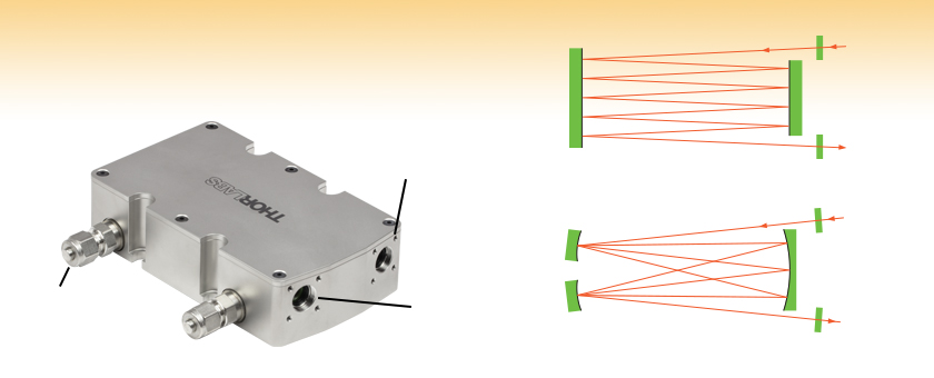
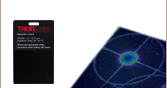
A multipass cell increases the path length of a beam through the cell:
The MGC3C(/M)-P01 multipass White cell (above) has 31 internal reflections,
though only 7 are shown here for simplicity.
The MGC1C(/M)-P01 multipass cell (above) has 9 internal reflections.


Please Wait
Click to Enlarge
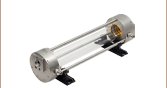
The gas interface features nozzle arrays for laminar gas flow and short gas exchange times.
(Render of MGC1C-P01 Cell Shown)
Applications
- Absorption Spectroscopy
- Breath or Process Gas Analysis
- Environmental Monitoring
- Medical Diagnostics
- Instrument Calibration
- Combustion Processes

Click to Enlarge
The interface on each mounting face is angled at the necessary beam injection angle for ease of alignment; see the Getting Started tab above for details.
(MGC3C-P01 Cell Shown)
Features
- Multipass Gas Cell Designs Increase Absorption in Spectroscopic Measurements
- MG1C(/M)-P01 Cell with Plano Mirrors and 1 m Optical Path Length (OPL)
- MG3C(/M)-P01 White Cell with Spherical Mirrors and 3.2 m OPL
- Compact Housings with 100 mL Gas Volume for Fast Gas Exchange Rates
- 450 nm to 8 µm Operating Wavelength
- Ø1/2" Calcium Fluoride Wedged Windows (User Replaceable)
- Protected Silver Coated Mirrors
- Gas Interface: Ø1/4" or Ø6 mm Swagelok® Tube Fittings (Included)
- Each Cell is Individually Tested for Pressure and Leakage
- Operating Pressure Range: <10-5 Torr up to 2 atm
- Gas Leakage Rate: <10-6 Torr·L/s
- Compatible with Thorlabs' 16 mm Cage System
- Contact Tech Support for Custom Units with Other Windows, Mirror Coatings, Gas Ports, or O-Ring Materials
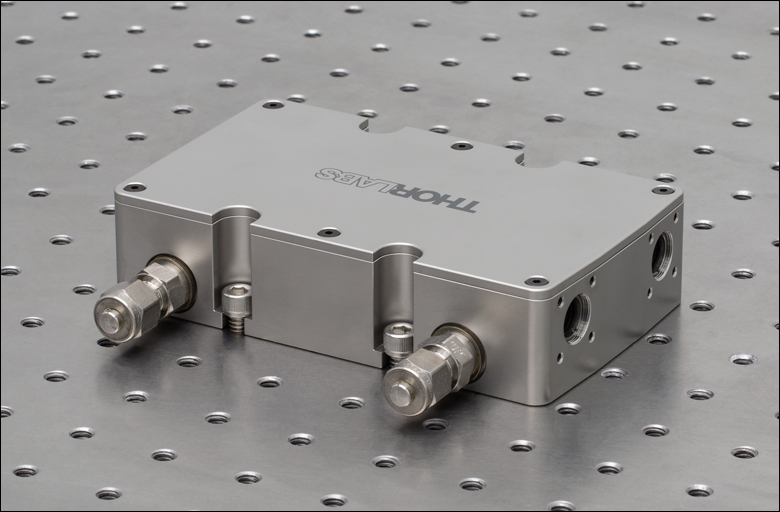
Thorlabs' MGC1C(/M)-P01 and MGC3C(/M)-P01 Multipass Gas Cells are compact solutions for achieving long path lengths in gas absorption spectroscopy applications. Each MGC1C(/M)-P01 cell features a 1 m optical path length (OPL) and flat mirrors, while the MGC3C(/M)-P01 cell features a 3.2 m OPL White cell design with spherical mirrors. Both cells support a maximum beam diameter (1/e2) of 1 mm; for interference-free operation, the 1 m multipass cell requires the beam to be focused such that the beam waist in the optical center of the cell, while the 3.2 m White cell supports a collimated beam or beams that are focused in the physical middle of the cell.
In a White cell, the spherical mirrors act like lenses separated by 2 focal lengths. Hence, the beam is repeatedly imaged after a distance 4 focal lengths, just like any 4f optical system. This makes the White cell especially suitable for providing a long optical path length in a small sample volume.
Both variants have mirrors with protected silver coatings designed for excellent performance over the 450 nm to 8 µm wavelength range. The optical apertures feature angled walls with 4-40 threaded holes for ease of alignment using 16 mm cage components. On the side of the cell are two gas connection ports for use in either a static pressure configuration or as a flow cell. All multipass cells are individually vacuum and leak tested to make sure each unit meets specifications. To request a quote for a custom compact multipass gas cell with other windows, mirror coatings, or gas ports, please contact Tech Support.
Compact Multipass Gas Cells
Thorlabs' long-optical-path absorption cells are used primarily for weak-trace-gas absorption spectroscopy applications such as environmental monitoring, combustion processes, medical diagnostics, and fundamental atomic and molecular physics. These gas cells provide relatively long absorption paths for sample volumes of only 100 mL. We also offer Herriott cells with 10.5 and 31.2 m optical path lengths.
Gas Interface
Each multipass cell is equipped with two gas connection ports. If not operated in a flow cell configuration, the second gas port could instead be used to connect a pressure gauge or other similar device to the cell. The gas ports are equipped with standard, male Swagelok® stainless steel tube fittings. Imperial cells feature fittings for 1/4" OD tubes while metric cells feature fittings for 6 mm OD tubes.
The tube fittings can be disconnected for access to the G1/8" parallel female thread connector in the cell housing. British Standard Parallel Piping (BSPP) pipes may be directly connected to the female thread connector. Note that the leakage rate is not guaranteed if the gas fitting is replaced or adjusted by the end user. If you are unsure how to connect the cell to your existing vacuum or gas supply system, please contact Tech Support.
Our compact multipass cells feature a unique gas flow design that uses two arrays of nozzles to provide laminar gas flow through major parts of the cell and a wide range of flow rates. This reduces dead volumes and turbulence within the cell and allows fast gas exchange rates for measurement. Either gas port can be used as input or output.
Angled Optical Ports
These multipass cells have two apertures that provide compatibility with our 16 mm cage system. The surface of each aperture is manufactured to be perpendicular to the nominal beam path to simplify alignment. For details on how to take advantage of these mounting features, even when operating the cell with free-space optics not directly attached to the cell, please refer to the Getting Started tab above. These cells have been designed such that the optical input and output are on the same side of the cell and in the plane of the optical table. Either optical port can be used as input or output. Please click the Documents (![]() ) icons below for details.
) icons below for details.
| Key Specsa | |||||||||
|---|---|---|---|---|---|---|---|---|---|
| Item # | Operating Wavelength |
Optical Path Length (OPL) |
Internal Reflections |
Max Beam Diameter (1/e2) |
Beam Angles of Incidence |
Mirrors | Sample Volume |
Swagelok® Gas Interface | Operating Temperature |
| MGC1C-P01 | 450 nm to 8 µmb | 1028 ± 0.5 mm | 9 | 1 mmc | ±2.7° Horizontal, 0° Vertical |
Plano, Silver Coated |
100 mL | 1/4" OD Tube Fittings | -5 to 80 °C (Non-Condensing) |
| MGC1C/M-P01 | 6 mm OD Tube Fittings | ||||||||
| MGC3C-P01 | 3231 ± 0.5 mm | 31 | 1 mmd | ±7.8° Horizontal, 0° Vertical |
Spherical, Silver Coated |
1/4" OD Tube Fittings | |||
| MGC3C/M-P01 | 6 mm OD Tube Fittings | ||||||||
| Item # | MGC1C-P01 | MGC1C/M-P01 | MGC3C-P01 | MGC3C/M-P01 |
|---|---|---|---|---|
| Optical Specifications | ||||
| Operating Wavelength Range |
450 nm to 8 µma | |||
| Optical Path Lengthb | 1028 ± 0.5 mm | 3231 ± 0.5 mm | ||
| Number of Internal Reflections | 9 | 31 | ||
| Max Input Beam Diameter (1/e2, Collimated) |
1 mmc | 1 mmd | ||
| Beam Angles of Incidence |
±2.7° Horizontal, 0° Vertical | ±7.8° Horizontal, 0° Vertical | ||
| Mirror Coating | Protected Silver (-P01) Coating | |||
| Mirror Substrate | UV Fused Silica | N-BK7 | ||
| Mirror Type | Plano | Spherical, White Configuration | ||
| Windows | WW50530 Uncoated Calcium Fluoride Wedged Windows | |||
| Gas Specifications | ||||
| Supported Pressure | <10-5 Torr - 2 atm (1520 Torr) | |||
| Gas Leakage Rated | <10-6 Torr·L/s | |||
| Sample Volume | 100 mL | |||
| Swagelok® Gas Interface | 1/4" OD Tube | 6 mm OD Tube | 1/4" OD Tube | 6 mm OD Tube |
| Fitting Interface in Housing | Female G1/8" Straight Thread | |||
| Materials in Contact with Gas Sample |
Stainless Steel (1.4301, 17-7), FKM (Viton), Calcium Fluoride, Silver with Protective Overcoat per MIL-C-48497A |
|||
| UV Fused Silica | N-BK7 | |||
| General Specifications | ||||
| Bake-Out Temperature | 80 °C Max | |||
| Operating Temperature | -5 to 80 °C (Non-Condensing) | |||
| Storage Temperature | -20 to 80 °C | |||
| Dimensions (L x W x H) | 137.0 mm x 110.5 mm x 33.5 mm (5.39" x 4.35" x 1.32") |
137.0 mm x 110.5 mm x 36.0 mm (5.39" x 4.35" x 1.42") |
||
| Mass (Weight) | 2.1 kg (4.6 lbs) | |||
| Mirror Specifications | ||
|---|---|---|
| Coating | Silver with Protective Overcoat (-P01) | |
| Avg. Reflectance | >97% (450 nm - 2 µm) >95% (2 - 20 µm) |
|
| Reflectance Plots (Click for Details) |
||
| Damage Threshold |
Pulsed | 0.225 J/cm2 (800 nm, 99 fs, 1 kHz, Ø0.167 mm) 1 J/cm2 (1064 nm, 10 ns, 10 Hz, Ø1.010 mm) |
| CWa | 500 W/cm (1.07 µm, Ø0.974 mm) 1500 W/cm (10.6 µm, Ø0.339 mm) |
|
| Substrate | MGC1C(/M)-P01 | UV Fused Silicab |
| MGC3C(/M)-P01 | N-BK7b | |
| Window Specifications | ||
|---|---|---|
| Item # | WW50530 | |
| Diameter | 1/2" (12.7 mm) | |
| Diameter Tolerance | +0.0 / -0.2 mm | |
| Thickness | 3.0 mm | |
| Thickness Tolerance | ±0.1 mm | |
| Clear Aperture | ≥Ø11.43 mm | |
| Transmission Plot (Click for Details) |
 Raw Data |
|
| Wedge Angle | 30 arcmin | |
| Wedge Angle Tolerance | ±10 arcmin | |
| Surface Flatnessa | ≤λ/16 Over Central Ø5 mm; ≤λ/8 Full Clear Aperture |
|
| Surface Quality | 40-20 Scratch-Dig | |
| Substrate | Calcium Fluorideb | |
Click to Enlarge
Click Here for Raw Data
This graph shows simulated throughput for our compact multipass cells using measured transmission values for the calcium fluoride windows and measured reflectance values for the protected silver mirrors. The shaded region in the graph denotes the recommended operating wavelength range. For more information, please see the Troubleshooting section of the Getting Started tab above, or contact Tech Support.
Click to Enlarge
Click Here for Raw Data
This graph shows the measured transmission of an uncoated calcium fluoride window at normal incidence.
Click to Enlarge
Click Here for Raw Data
This graph shows the measured reflectance of our protected silver mirrors near normal incidence. The shaded region in the graph denotes the range over which we guarantee the specified reflectance. Please note that the reflectance outside of this band is typical and can vary from lot to lot, especially in out-of-band regions where the reflectance is fluctuating or sloped.
Click to Enlarge
The cell housing features slots for 1/4"-20 (M6 x 1.0) screws as well as 1" (25.0 mm) hole spacing for imperial and metric compatibility.
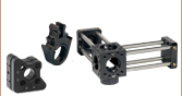
Click to Enlarge
Each mounting plate is angled at the necessary beam insertion angle for ease of alignment. SR4 Cage Rods with SCPA1 Alignment Plates are shown.
Getting Started
First place the compact multipass gas cell on an optical table or breadboard or mount it on posts. The cell's mounting slot spacing is compatible with most of our optical tables and breadboards, including those with 1" spacings and 1/4"-20 taps as well as 25.0 mm spacings and M6 x 1.0 taps. Secure the cell using cap screws, shown in the photo to the right. It is possible to adjust the height of the cell by mounting it on optical posts first [such as RS1P(/M) pedestal posts], which are in turn secured to the optical table [using CF175C(/M) clamps, for example]. Next, remove the caps (replacement Item # SM05CP2) from each optical port. The cell can be used in either direction, in the sense that there is no designated input or output.
Both optical interface surfaces provide compatibility with Thorlabs' 16 mm cage system, as illustrated in the photo to the lower right. They are machined to be perpendicular to the nominal beam path, simplifying alignment. Note that to reduce background effects, the cell windows are mounted at a slight angle relative to the nominal optical beam path.
Each gas port is sealed with an end plug, which must be removed prior to connecting a tube or gas pipe to the port. The plug can be removed using a 9/16" (14 mm) wrench; make sure the gas port adapter is held firmly in the cell housing by using another 9/16" (14 mm) wrench while removing the Swagelok® plug. To seal a gas port, leave a plug tightened onto it.
Alignment
The alignment of an incoming free-space beam can be simplified using cage rods and our alignment tools. For example, connect 16 mm cage assembly rods (e.g. Item # SR4) to one of the optical interfaces and use a cage system target plate (Item # SCPA1) as shown in the photo to the right (only the upper two rods are necessary in this scenario). Be careful to put the target plate perpendicular to the rods. Note that these interfaces are only angled in the horizontal plane, so the optical axis of a connected cage system will be parallel to the table surface. Initial alignment can be achieved by aligning the beam along the optical axis defined by the mounting interface. Please note that the mounting interfaces have a tolerance of ±0.3°. We recommend limiting the beam diameter to 1 mm (1/e2) at the cell windows. We also recommend:
- For the MGC1C(/M)-P01 cell: Position the beam waist 0.5 m behind the input window (at the optical center of the cell).
- For the MGC3C(/M)-P01 cell: Focus the beam between the large mirror and the first small mirror (in line with the middle screws on the lid). Use a lens with focal length ≥300 mm to avoid overfilling the smaller mirrors.
This ensures that a collimated beam at the cell input does not lead to an overspill of light on the mirrors or the cell body, causing background signals.
We also recommend the use of two folding mirrors prior to the multipass cell to position and angle the incident beam. After initial alignment, make sure that the beam is not truncated by the apertures. This can be done by carefully introducing small misalignments to the beam and monitoring the cell transmitted intensity with a large-area photodetector (making sure all transmitted light is being detected); the transmitted power should not change as the small misalignments are introduced.
Please note that truncation of the beam by any element along the path will result in a residual background signal imposed on the spectroscopic signal, reducing the system's overall performance. For the MGC1C(/M)-P01 cell, we suggest removing the lid of the cell; this enables close monitoring of the beam path throughout the cell. When operating the cell with invisible laser light, pre-aligning the system with visible laser light (e.g. in the reverse beam direction) can simplify the alignment of the invisible beam.
Using the MGC1C(/M)-P01 Cell for Other Path Lengths
Path lengths longer or shorter than 1 m (integer multiples of approximately 0.2 m) can be obtained with a different input beam angle. Note that the clear aperture decreases for path lengths other than 1 m because of the mechanical apertures, further restricting the beam diameter. The cover of the cell may be opened to trace the beam inside the cell or count the number of reflections on the mirrors to ensure that desired optical path length is obtained.
Troubleshooting
Background Signals
It is possible that the spectroscopic signal observed after the multipass cell is deteriorated by fringes. Among other reasons (e.g. standing waves in optical elements before or after the cell, or standing waves between optical surfaces), this problem can occur when the light beam is truncated. Please ensure that:
- The beam size does not exceed the maximum allowed beam size for the cell, and
- The beam enters/leaves the cell through the center of the mirror holes without being cropped.
Please use caution when handling these cells so that the gas ports, windows, and mirrors are not damaged. Please refer to the sections below for instructions on replacing user-serviceable components. Please contact Tech Support with questions on these procedures.
Gas Ports
The gas port Swagelok® fittings can be replaced with other fittings with male G1/8" British Standard Parallel Piping (BSPP) threads. The stock fitting can be removed using a 9/16" (14 mm) wrench. As a gasket replacement, use SS-2-RS-2V from Swagelok. When replacing gaskets, make sure to wear gloves to protect yourself and to avoid fingerprints on sealing surfaces. Make sure to clean the sealing surfaces properly before installing the new gasket. We recommend a mix of 50% isopropanol and 50% ethanol. Blow away any dust and small residual particles from both the gasket and sealing surface using a pressurized duster.
Window Replacement
The pair of WW50530 Uncoated Calcium Fluoride Wedged Windows included with each multipass cell can be removed and replaced with windows of the same thickness and diameter. Each window is secured with a POLARIS-SM05RR SM05-Threaded Retaining Ring, which can be removed with an SPW603 Spanner Wrench. The windows should be installed with the thick edge facing inwards. There is also a Viton O-ring (9.25 mm inner diameter x 1.78 mm thick) between each window and the cell and a Viton X-ring (9.25 mm inner diameter x 1.78 mm thick) between each window and retaining ring. Note that replacing the included wedged windows with flat windows with parallel sides may cause a weak fringing effect. If this reduces the system's overall performance noticeably, revert to using wedged windows.
Note that the beam alignment may need to be adjusted after replacing or cleaning the windows.
Lid O-Ring Replacement
If the cell lid is frequently removed, the O-ring may eventually need to be replaced; the dimensions of the O-ring are 106 mm inner diameter x 2 mm thick and the material is Viton (FKM80).

Multipass Cell Considerations
Multipass cells can be implemented into optical setups in a wide variety of configurations, both from an optical point of view and a vacuum system point of view. Optically, there are two fundamentally different approaches when using a cell for analytical spectroscopic applications. These approaches differ in how the spectrum is resolved in the system. One of these approaches is to couple in a tunable narrowband light source (most often a laser) into the cell and then use a photodetector on the other side of the cell for analysis. In this case, the light source is the spectrally resolving part; by tuning the frequency of the light source over a spectral feature of the target analyte and by knowing the relevant experimental parameters, quantitative spectroscopy can be performed. The other approach incorporates a broadband source (e.g. Globar, LED, superluminescent source, or a broad linewidth laser) and a spectrally resolving device at the output of the cell, for instance a Fourier-based optical spectrum analyzer, a grating, or a tunable optical filter. It is important in all cases that the system is capable of precisely selecting a target feature at a specific wavelength.
Before a gas sample can be analyzed, it must fill the multipass cell. A number of parameters must be determined in order to find a system design that meets the requirements imposed by the spectroscopic application. The answers to the following questions will help you decide on the experimental setup:
- Can the experiment be run by evacuating the cell and subsequently filling it with the analyte under investigation (static pressure experiment) or is there a need of a continuous flow of the analyte through the cell for uninterrupted monitoring of the target feature (flow cell configuration)?
- What time resolution is needed? For static pressure measurements, this requires an answer to the questions of whether and how fast a background signal must be acquired; for flow cell experiments, one needs to decide what flow rate is required to ensure a gas exchange inside the cell fast enough to reach the time resolution needed for the experiment.
- What is the optimal pressure for the experiment? Can the cell be used at atmospheric pressure or does the experiment require sub-atmospheric pressures for optimal detection conditions considering absorption features are likely to interfere at atmospheric pressure conditions.
- Does the sample require preparation before being directed into the multipass cell? This might for instance involve the removal of water, oil, or solid particles (e.g. dust or soot) from the sample to prevent interference with the target feature or contamination of the cell.
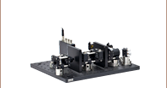
Example Applications
The three sample configurations below include either a pressure gauge, a mass flow controller, or both. Additional valves may be useful for improved control over the pressure or flow rate. Note that the multipass cell may be mounted on a PTC1(/M) temperature-controlled breadboard as shown above to heat or cool the cell.

Click to Enlarge
Figure 1: Flow Cell Configuration at Atmospheric Pressure
Example 1: Flow Cell Configuration at Atmospheric Pressure
This setup for a typical flow cell configuration at atmospheric pressure is illustrated in Figure 1 to the right. One or more samples are connected to a mass flow controller installed in-line between the cell and the sample (a gas cylinder, pipeline, etc.). The mass flow controller allows the mass flow rate through the cell to be set accurately. For less demanding experiments, the mass flow controller can be replaced by needle valves for less robust control of the flow rate.
Example 2: Flow Cell Configuration at Sub-Atmospheric Pressure
In this example, a gas sample passes a needle valve before it enters the cell. The cell output is evacuated by a pump where the pumping speed can be adjusted with another needle valve between the cell output and the pump. Balancing the two needle valves allows for adjustment of both pressure and mass flow rate through the cell. For a true reading of the pressure inside the cell it is important to install the pressure gauge between the two needle valves. An optional mass flow meter in-line with the gas flow (as illustrated in Figure 2 to the lower left) provides a reading of the mass flow through the cell.
Example 3: Steady State Sub-Atmospheric Pressure Experiment
This setup for a typical steady state experiment at sub-atmospheric pressures is illustrated in Figure 3 below. Before a sample is directed into the multipass cell, the cell is evacuated by a pump system, e.g. by a turbomolecular pump backed by a fore-vacuum (backing) pump. A pressure gauge connected to the cell allows the user to measure the pressure present inside the cell. Once the cell is evacuated, the pump is disconnected by closing the valve next to the pump system. Carefully opening the valve closest to the sample container (e.g. a gas cylinder or Tedlar bags containing either human breath or other gases collected at a remote test site) allows the cell to be filled with the sample; once the desired end pressure is reached, the inlet valve is closed and a measurement can be executed.

Click to Enlarge
Figure 2: Flow Cell Configuration at Sub-Atmospheric Pressure
Click to Enlarge
Figure 3: Steady State Sub-Atmospheric Pressure Experiment
| Damage Threshold Specifications | ||
|---|---|---|
| Coating Designation (Item # Suffix) |
Damage Threshold | |
| -P01 | Pulsed | 0.225 J/cm2 (800 nm, 99 fs, 1 kHz, Ø0.167 mm) 3 J/cm2 (1064 nm, 10 ns, 10 Hz, Ø1.000 mm) |
| CWa | 500 W/cm (1.07 µm, Ø0.974 mm) 1500 W/cm (10.6 µm, Ø0.339 mm) |
|
Damage Threshold Data for Thorlabs' -P01 Coated Protected Silver Mirrors
The specifications to the right are measured data for Thorlabs' protected silver mirrors with a -P01 coating. Damage threshold specifications are constant for this coating type, regardless of the size or shape of the mirror.
Laser Induced Damage Threshold Tutorial
The following is a general overview of how laser induced damage thresholds are measured and how the values may be utilized in determining the appropriateness of an optic for a given application. When choosing optics, it is important to understand the Laser Induced Damage Threshold (LIDT) of the optics being used. The LIDT for an optic greatly depends on the type of laser you are using. Continuous wave (CW) lasers typically cause damage from thermal effects (absorption either in the coating or in the substrate). Pulsed lasers, on the other hand, often strip electrons from the lattice structure of an optic before causing thermal damage. Note that the guideline presented here assumes room temperature operation and optics in new condition (i.e., within scratch-dig spec, surface free of contamination, etc.). Because dust or other particles on the surface of an optic can cause damage at lower thresholds, we recommend keeping surfaces clean and free of debris. For more information on cleaning optics, please see our Optics Cleaning tutorial.
Testing Method
Thorlabs' LIDT testing is done in compliance with ISO/DIS 11254 and ISO 21254 specifications.
First, a low-power/energy beam is directed to the optic under test. The optic is exposed in 10 locations to this laser beam for 30 seconds (CW) or for a number of pulses (pulse repetition frequency specified). After exposure, the optic is examined by a microscope (~100X magnification) for any visible damage. The number of locations that are damaged at a particular power/energy level is recorded. Next, the power/energy is either increased or decreased and the optic is exposed at 10 new locations. This process is repeated until damage is observed. The damage threshold is then assigned to be the highest power/energy that the optic can withstand without causing damage. A histogram such as that below represents the testing of one BB1-E02 mirror.
The photograph above is a protected aluminum-coated mirror after LIDT testing. In this particular test, it handled 0.43 J/cm2 (1064 nm, 10 ns pulse, 10 Hz, Ø1.000 mm) before damage.
| Example Test Data | |||
|---|---|---|---|
| Fluence | # of Tested Locations | Locations with Damage | Locations Without Damage |
| 1.50 J/cm2 | 10 | 0 | 10 |
| 1.75 J/cm2 | 10 | 0 | 10 |
| 2.00 J/cm2 | 10 | 0 | 10 |
| 2.25 J/cm2 | 10 | 1 | 9 |
| 3.00 J/cm2 | 10 | 1 | 9 |
| 5.00 J/cm2 | 10 | 9 | 1 |
According to the test, the damage threshold of the mirror was 2.00 J/cm2 (532 nm, 10 ns pulse, 10 Hz, Ø0.803 mm). Please keep in mind that these tests are performed on clean optics, as dirt and contamination can significantly lower the damage threshold of a component. While the test results are only representative of one coating run, Thorlabs specifies damage threshold values that account for coating variances.
Continuous Wave and Long-Pulse Lasers
When an optic is damaged by a continuous wave (CW) laser, it is usually due to the melting of the surface as a result of absorbing the laser's energy or damage to the optical coating (antireflection) [1]. Pulsed lasers with pulse lengths longer than 1 µs can be treated as CW lasers for LIDT discussions.
When pulse lengths are between 1 ns and 1 µs, laser-induced damage can occur either because of absorption or a dielectric breakdown (therefore, a user must check both CW and pulsed LIDT). Absorption is either due to an intrinsic property of the optic or due to surface irregularities; thus LIDT values are only valid for optics meeting or exceeding the surface quality specifications given by a manufacturer. While many optics can handle high power CW lasers, cemented (e.g., achromatic doublets) or highly absorptive (e.g., ND filters) optics tend to have lower CW damage thresholds. These lower thresholds are due to absorption or scattering in the cement or metal coating.
LIDT in linear power density vs. pulse length and spot size. For long pulses to CW, linear power density becomes a constant with spot size. This graph was obtained from [1].
Pulsed lasers with high pulse repetition frequencies (PRF) may behave similarly to CW beams. Unfortunately, this is highly dependent on factors such as absorption and thermal diffusivity, so there is no reliable method for determining when a high PRF laser will damage an optic due to thermal effects. For beams with a high PRF both the average and peak powers must be compared to the equivalent CW power. Additionally, for highly transparent materials, there is little to no drop in the LIDT with increasing PRF.
In order to use the specified CW damage threshold of an optic, it is necessary to know the following:
- Wavelength of your laser
- Beam diameter of your beam (1/e2)
- Approximate intensity profile of your beam (e.g., Gaussian)
- Linear power density of your beam (total power divided by 1/e2 beam diameter)
Thorlabs expresses LIDT for CW lasers as a linear power density measured in W/cm. In this regime, the LIDT given as a linear power density can be applied to any beam diameter; one does not need to compute an adjusted LIDT to adjust for changes in spot size, as demonstrated by the graph to the right. Average linear power density can be calculated using the equation below.

The calculation above assumes a uniform beam intensity profile. You must now consider hotspots in the beam or other non-uniform intensity profiles and roughly calculate a maximum power density. For reference, a Gaussian beam typically has a maximum power density that is twice that of the uniform beam (see lower right).
Now compare the maximum power density to that which is specified as the LIDT for the optic. If the optic was tested at a wavelength other than your operating wavelength, the damage threshold must be scaled appropriately. A good rule of thumb is that the damage threshold has a linear relationship with wavelength such that as you move to shorter wavelengths, the damage threshold decreases (i.e., a LIDT of 10 W/cm at 1310 nm scales to 5 W/cm at 655 nm):

While this rule of thumb provides a general trend, it is not a quantitative analysis of LIDT vs wavelength. In CW applications, for instance, damage scales more strongly with absorption in the coating and substrate, which does not necessarily scale well with wavelength. While the above procedure provides a good rule of thumb for LIDT values, please contact Tech Support if your wavelength is different from the specified LIDT wavelength. If your power density is less than the adjusted LIDT of the optic, then the optic should work for your application.
Please note that we have a buffer built in between the specified damage thresholds online and the tests which we have done, which accommodates variation between batches. Upon request, we can provide individual test information and a testing certificate. The damage analysis will be carried out on a similar optic (customer's optic will not be damaged). Testing may result in additional costs or lead times. Contact Tech Support for more information.
Pulsed Lasers
As previously stated, pulsed lasers typically induce a different type of damage to the optic than CW lasers. Pulsed lasers often do not heat the optic enough to damage it; instead, pulsed lasers produce strong electric fields capable of inducing dielectric breakdown in the material. Unfortunately, it can be very difficult to compare the LIDT specification of an optic to your laser. There are multiple regimes in which a pulsed laser can damage an optic and this is based on the laser's pulse length. The highlighted columns in the table below outline the relevant pulse lengths for our specified LIDT values.
Pulses shorter than 10-9 s cannot be compared to our specified LIDT values with much reliability. In this ultra-short-pulse regime various mechanics, such as multiphoton-avalanche ionization, take over as the predominate damage mechanism [2]. In contrast, pulses between 10-7 s and 10-4 s may cause damage to an optic either because of dielectric breakdown or thermal effects. This means that both CW and pulsed damage thresholds must be compared to the laser beam to determine whether the optic is suitable for your application.
| Pulse Duration | t < 10-9 s | 10-9 < t < 10-7 s | 10-7 < t < 10-4 s | t > 10-4 s |
|---|---|---|---|---|
| Damage Mechanism | Avalanche Ionization | Dielectric Breakdown | Dielectric Breakdown or Thermal | Thermal |
| Relevant Damage Specification | No Comparison (See Above) | Pulsed | Pulsed and CW | CW |
When comparing an LIDT specified for a pulsed laser to your laser, it is essential to know the following:
LIDT in energy density vs. pulse length and spot size. For short pulses, energy density becomes a constant with spot size. This graph was obtained from [1].
- Wavelength of your laser
- Energy density of your beam (total energy divided by 1/e2 area)
- Pulse length of your laser
- Pulse repetition frequency (prf) of your laser
- Beam diameter of your laser (1/e2 )
- Approximate intensity profile of your beam (e.g., Gaussian)
The energy density of your beam should be calculated in terms of J/cm2. The graph to the right shows why expressing the LIDT as an energy density provides the best metric for short pulse sources. In this regime, the LIDT given as an energy density can be applied to any beam diameter; one does not need to compute an adjusted LIDT to adjust for changes in spot size. This calculation assumes a uniform beam intensity profile. You must now adjust this energy density to account for hotspots or other nonuniform intensity profiles and roughly calculate a maximum energy density. For reference a Gaussian beam typically has a maximum energy density that is twice that of the 1/e2 beam.
Now compare the maximum energy density to that which is specified as the LIDT for the optic. If the optic was tested at a wavelength other than your operating wavelength, the damage threshold must be scaled appropriately [3]. A good rule of thumb is that the damage threshold has an inverse square root relationship with wavelength such that as you move to shorter wavelengths, the damage threshold decreases (i.e., a LIDT of 1 J/cm2 at 1064 nm scales to 0.7 J/cm2 at 532 nm):

You now have a wavelength-adjusted energy density, which you will use in the following step.
Beam diameter is also important to know when comparing damage thresholds. While the LIDT, when expressed in units of J/cm², scales independently of spot size; large beam sizes are more likely to illuminate a larger number of defects which can lead to greater variances in the LIDT [4]. For data presented here, a <1 mm beam size was used to measure the LIDT. For beams sizes greater than 5 mm, the LIDT (J/cm2) will not scale independently of beam diameter due to the larger size beam exposing more defects.
The pulse length must now be compensated for. The longer the pulse duration, the more energy the optic can handle. For pulse widths between 1 - 100 ns, an approximation is as follows:

Use this formula to calculate the Adjusted LIDT for an optic based on your pulse length. If your maximum energy density is less than this adjusted LIDT maximum energy density, then the optic should be suitable for your application. Keep in mind that this calculation is only used for pulses between 10-9 s and 10-7 s. For pulses between 10-7 s and 10-4 s, the CW LIDT must also be checked before deeming the optic appropriate for your application.
Please note that we have a buffer built in between the specified damage thresholds online and the tests which we have done, which accommodates variation between batches. Upon request, we can provide individual test information and a testing certificate. Contact Tech Support for more information.
[1] R. M. Wood, Optics and Laser Tech. 29, 517 (1998).
[2] Roger M. Wood, Laser-Induced Damage of Optical Materials (Institute of Physics Publishing, Philadelphia, PA, 2003).
[3] C. W. Carr et al., Phys. Rev. Lett. 91, 127402 (2003).
[4] N. Bloembergen, Appl. Opt. 12, 661 (1973).
| Posted Comments: | |
諒一 芝山
(posted 2024-04-09 16:47:05.02) Φ1mmのビームを入射する際のコリメート度合について:
入射するビームサイズは1mm以下と規定がありますが、
出射するビームサイズは窓サイズ以下であれば問題ないでしょうか?(*内部パス(1028mm)で窓サイズまで広がる程度のコリメート度合で良いのか) srydberg
(posted 2024-04-10 04:32:11.0) Hi, thank you for contacting Thorlabs!
In order to not crop the beam in the MGC1C/M-P01, the beam has to be max 1mm at the input and focused at least halfway (<500mm) so that it's no larger than 1mm at the output. 諒一 芝山
(posted 2024-04-04 15:16:52.55) 同製品の購入を検討しております。
注文した場合、納期はどの程度掛かる見込みでしょうか? fnero
(posted 2024-04-05 03:10:41.0) Thanks for posting on our website feedback page. The availability of our products can be seen on the website, in the column "Available". If it states "today" it is available for shipping today. For further details, please reach out to your local sales office. user
(posted 2024-03-14 05:56:40.927) Hi i am looking for air pump to pump a MGC3C-P01
Are there any limitations to it not being plastic, can you recommend such a pump to me? Does it matter whether I pump the gas or compress it or do I need two pumps, one for compression and one for pumping fnero
(posted 2024-03-14 09:07:23.0) Thank you for your question. We have specifications on the supported pressure range for the gas cell, <10-5 Torr - 2 atm (1520 Torr). We have reached out to you to discuss your application in detail. |