2x2 Double-Clad Fiber Couplers
- 430 - 680 nm or 960 - 1260 nm Wavelength Range
- Single Mode Core Insertion Loss of ≤0.5 dB
- At Least 60% Multimode Inner Cladding Transfer
DC1060LEFA
1060 nm Double-Clad Fiber
Coupler with Connectors
DC530SEFA
530 nm Double-Clad Fiber Coupler with Connectors

Please Wait
Click to Enlarge
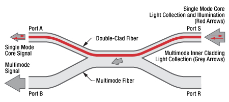
Figure 1.1 This schematic shows the internal structure of a double-clad fiber coupler. Single mode light input at Port A is used to illuminate a sample at Port S. Single mode and multimode light from the sample enters the single mode core (shown in red) and multimode inner cladding (shown in grey) of the DCF at Port S. The single mode signal travels through the core of the DCF and is output at port A; the multimode signal is transferred from the DCF to the multimode fiber and is output at Port B.
Applications
- Optical Coherence Tomography (OCT)
- Fluorescence Imaging
- Confocal Microscopy
- Spectroscopy
- Surface Plasmon Resonance (SPR) Sensing
- Speckle-Free Single-Fiber Endoscopy
- LIDAR

Figure 1.2 Fiber leads containing double-clad fiber are color-coded white (Ports A and S) and fiber leads containing multimode fiber are color-coded orange (Ports B and R).
Features
- Two Wavelength Ranges
- 430 - 680 nm
- 960 - 1260 nm
- ≤0.5 dB Single Mode Core Insertion Loss
- At Least 60% Multimode Inner Cladding Transfer
- All Models Available With Connectors
- 0.5 m or 1.0 m +0.075 / -0.0 m Long Fiber Leads
- Individualized Data Sheet Included with Each Coupler
(See the Verification Tab; Sample Data Sheets Available for 530 nm or 1060 nm)
Thorlabs is collaborating with strategic partner Castor Optics to design and manufacture a family of Double-Clad Fiber Couplers. These 2x2 Double-Clad Fiber Couplers combine a double-clad fiber (single mode core surrounded by a multimode inner cladding) with a standard step-index multimode fiber, as shown in Figure 1.1. Light in the single mode core transmits with virtually no loss over the 430 - 680 nm or 960 - 1260 nm wavelength range, depending upon the coupler. The multimode transfer, defined as the ratio of the output signal at Port B to the input signal at Port S, is ≥60% over a wider wavelength range of 400 - 1750 nm, excluding the water absorption region around 1383 nm. Figure 1.1 depicts both single mode and multimode signals through a DCF coupler. Double-clad fiber couplers are well suited for applications at 530 nm and 1060 nm.
These optical properties allow double-clad fiber couplers to function as an alternative to free-space assemblies in many applications, including imaging and sensing. Our 1060 nm couplers are useful for applications such as spectrally encoded scanning laser ophthalmoscope (SESLO) OCT, which enable applications such as non-invasive imaging of the human retina. Our 530 nm coupler features a small inner cladding (Ø15 µm) that makes it ideal for applications in confocal microscopy. Please see the Applications tab for more information.
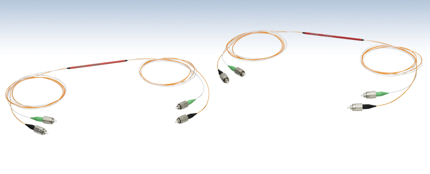
The fiber in each leg is jacketed in a Ø900 µm Hytrel®* tube, color-coded white for the DCF legs (Port A and Port S) and orange for the MM fiber legs (Port B and Port R), as shown in Figure 1.2.
These couplers are housed inside of a protective tube and are available with a mix of 2.0 mm narrow key FC/PC and FC/APC connectors. In general, FC/APC connectors reduce back reflections from the single mode core of the double-clad fiber leg of the coupler; reflection is not an issue for the multimode output port, so an FC/PC connector is used for easier integration with other fiber components. The DC530SEFA and DC1060LEFA include an FC/PC connector on port R to allow for connection to a beam trap when used with a mating sleeve. Please refer to the diagrams in Tables 638A and 577A for specific connector configurations.
Custom connector configurations and different performance characteristics may be available; please contact info@castoroptics.com with all custom inquiries.
*Hytrel® is a registered trademark of DuPont Polymers, Inc.
| Webpage Features | |
|---|---|
| |
Clicking this icon below will open a window that contains specifications and drawings. |
Double-Clad Fiber Coupler (DCFC) Applications
Double-Clad Fiber Couplers can be implemented in many imaging, photonics, and LIDAR applications. The following examples specifically illustrate how DCFCs can be used in confocal microscopy, OCT, and endoscopy applications.
Click to Enlarge
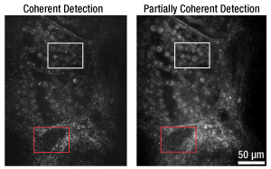
Figure 2.1 Comparison of confocal images taken using a single mode fiber coupler (left) and the DC780SEFA* DCFC (right).
Confocal Microscopy and Partially Coherent Detectiona
In a free-space confocal microscope, pinhole apertures only allow coherent light at the focal plane to reach the detector, which enables optical sectioning and high-resolution images over a narrow focal plane. Widening the detection aperture allows a small amount of partially coherent light to reach the detector, creating images with reduced speckle noise and increased contrast, but slightly reduced resolution.
This same effect can be achieved using a small-diameter DCFC, such as the DC780SEB*. In this scenario, the single mode core acts as an illumination pinhole while the small inner cladding (Ø26 µm) serves the purpose of the detection pinhole. Together, the core and inner cladding enable optical sectioning of the image just as in free space confocal microscopy. Using a DCFC in this manner ensures that the pinholes are always conjugate, because the detection pinhole surrounds the illumination pinhole. Finally, because the inner cladding diameter is just slightly larger than the core diameter, a small amount of partially coherent light is accepted, which reduces speckle noise and increases contrast.
Figure 2.1 compares images taken of a swine thyroid tissue section using a 50:50 single mode fiber coupler and a DC780SEFA* DCFC, respectively. As seen in comparing the white and red boxed sections in the left and right images, using a DCFC reduces speckle artifacts in the image while increasing contrast of cellular features within the tissue sample. Video 2.2 shows a series of confocal images taken of swine muscle tissue at depths from 15 µm to 105 µm using a single mode fiber coupler and a DC780SEB* double-clad fiber coupler.
*These previous-generation items are not available for individual purpose. The DC780SE2FA DCFC is available as an alternative.
Optical Coherence Tomography and Fluorescence Imagingb

Click to Enlarge
Figure 2.5 Combined OCT and Fluorescence Image
Click to Enlarge
Figure 2.4 Fluorescence Image
Click to Enlarge
Figure 2.3 OCT Image
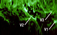
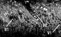
DCFCs can also be used instead of traditional dichroic beamsplitters to allow both OCT and fluorescence imaging of a sample using the same objective and scanning optics. The OCT signal (Figure 2.3) is collected in the single mode core of the double-clad fiber (DCF), while the fluorescence signal (Figure 2.4) is collected in the cladding. The core and cladding signals can be combined to produce a detailed image that distinguishes between bronchioles and blood vessels, as shown in Figure 2.5.
Click to Enlarge
Figure 2.7 Endoscopy Image Obtained Using an SM Fiber Coupler
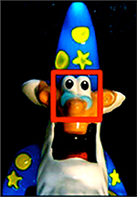
Figure 2.6 Photo of Sample
Click to Enlarge
Figure 2.9 3D Image Generated from Speckle-Free Endoscopy Using a Double-Clad Fiber Coupler
Click to Enlarge
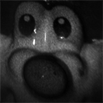
Figure 2.8 Speckle-Free Endoscopy Image Obtained Using a Double-Clad Fiber Coupler
Speckle-Free Endoscopyc
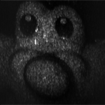
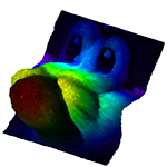
DCFCs can be used instead of traditional single mode 2x2 couplers in single-fiber endoscopy systems. When imaging a sample (Figure 2.6) with single mode fiber, laser speckle is present (Figure 2.7). Using both the single mode core and multimode cladding of the DCF for signal collection generates a higher quality image (Figure 2.8). Data from the core and inner cladding can also be used to create a three dimensional rendering of the subject as shown in Figure 2.9.
Video 2.10 shows a sequence of 99 images of a wasp head obtained using a DCFC. Speckle-free reflectance maps are acquired using light collected from the multimode cladding of the DCF (left panel of the video). The right panel of the video shows an overlay of the interferometric height profiles collected using the DCF single mode core on top of the reflectance maps. This technique enables the construction of a 3-D profile of the specimen and requires no special sample preparation.
References
Double-Clad Fiber Coupler Verification
Our double-clad fiber couplers undergo stringent verification testing during production. The setups shown in Figures 3.1 and 3.2 are used to obtain a single mode transmission spectrum, insertion loss, and the multimode inner cladding transfer specification. Each coupler has an individualized data sheet available, providing a summary of the results of these tests. Click for a sample data sheet for 530 nm or 1060 nm.

Click to Enlarge
Figure 3.1 Single Mode Insertion Loss and Transmission Measurement
Step 1: Single Mode Insertion Loss/Transmission Measurement
The single mode input of the coupler is connected to a Broadband Light Source (BBS) through a single mode fiber and a spool of double-clad fiber (DCF). The SM coupler output is spliced to a coiled SM patch cable (to ensure cladding modes are stripped) that is connected to an Optical Spectrum Analyzer (OSA). A spectrum is recorded before and after the fibers are fused to create the coupler. The difference between the two spectra can be defined as either Insertion Loss (dB) or Transmission (%).
Step 2: Multimode Transfer Measurement

Click to Enlarge
Figure 3.2 Multimode Transfer Measurement
The multimode input of the coupler is connected to a diffused 635 nm laser source through a Ø105 µm core / Ø125 μm cladding multimode fiber and a spool of DCF. Doing so ensures that the inner cladding modes are filled. The Ø200 µm core / Ø220 μm cladding multimode fiber output of the coupler is connected to a silicon photodiode optical power meter. A first optical power is recorded. The coupler is then removed from the measurement setup and the DCF spool is connected directly to the same power meter. A second optical power is recorded. The Multimode Inner Cladding Transfer is defined as the ratio of the first to second power measurements (%).

Castor Optics, a Montreal-based leading manufacturer of double-clad fiber couplers, has been a key strategic partner of Thorlabs since 2013. Castor was founded by Caroline Boudoux, Nicolas Godbout, Normand Brais, and Alex Cable to commercialize the innovative fiber coupler technology developed in the laboratory by Caroline Boudoux and Nicolas Godbout. The team at Castor works closely with Thorlabs' Montreal office to bring to market a broad range of fiber-based optical components for next-generation medical imaging devices and advanced instrumentation for use in the physical sciences.
About Caroline Boudoux
Caroline Boudoux earned her PhD from the Harvard-MIT Division of Health Sciences and Technology in 2007. She is an associate professor of engineering physics and principal investigator for the Laboratory for Optical Diagnoses and Imaging at École Polytechnique Montréal, a researcher at Sainte-Justine Hospital Research Center, and a visiting professor in the Department of Otology and Laryngology at Harvard Medical School. Her areas of research include biomedical imaging, optical coherence tomography, confocal and nonlinear microscopy, and endoscopic imaging.
About Nicolas Godbout
Nicolas Godbout obtained his PhD in Engineering Physics from École Polytechnique de Montréal in 2000. Follwing this, he led the optical design team at ITF Optical Technologies. He is currently a professor and principal investigator for the Optical Fibers Laboratory at École Polytechnique Montréal. His research interests include nonlinear and quantum optics, fiber lasers, fiber-optic design and fabrication, characterization techniques, and biophotonics.

Click to Enlarge
Figure 4.1 Professor Boudoux in the Laboratory
© Yves Beaulieu/Polytechnique Montréal

Click to Enlarge
Figure 4.2 Castor Optics at Photonics West 2016 Tradeshow
2015 Conference Presentations
L. Hariri, L. Bernstein, D. C. Adams, W.-J. Madore, A. J. Miller, M. Strupler, E. De Montigny, K. Beaudette, N. Godbout, C. Boudoux, and M. J. Suter. "Multimodal optical coherence tomography and fluorescence spectroscopy MEMS probe to assess inflammation in acute lung injury," in SPIE Photonics West, San Francisco, CA, 2015.
L. Bernstein, L. Hariri, W.-J. Madore, D. C. Adams, M. Strupler, E. De Montigny, K. Beaudette, Y. Wang, N. Godbout, M. J. Suter, and C. Boudoux. "Multimodal dual-clad fiber MEMS probe for simultaneous OCT and fluorescence imaging of inflammation in the lung," in SPIE Photonics West, San Francisco, CA, 2015.
K. Beaudette, M. L. Villiger, M. Strupler, M. Shishkov, J. Ren,W.-J. Madore, N. Godbout, B. E. Bouma, and C. Boudoux. "Double clad fiber devices for combined optical coherence tomography and laser tissue coagulation," in SPIE Photonics West, San Francisco, CA, 2015.
Combined OCT and Fluorescence Imaging
D. Lorenser, B. C. Quirk, M. Auger,W.-J. Madore, R.W. Kirk, N. Godbout, D. D. Sampson, C. Boudoux, and R. A. McLaughlin. "Dual-modality needle probe for combined fluorescence imaging and three-dimensional
optical coherence tomography," Optics Letters, 38, 266 - 268 (2013).
L. Scolaro, L. Dirk, W.-J. Madore, A. Kramer, G. C. Yeoh, N. Godbout, D. D. Sampson, C. Boudoux, and R. A. McLaughlin, "Dual-modality Imaging Needle for Combined Optical Coherence Tomography and Fluorescence Imaging of Fluorescently Labelled Tissue," in Biomedical Optics 2014, OSA Technical Digest (online) (Optical Society of America, 2014), paper BS2B.7.
Surface Plasmon Resonance (SPR) Sensing
M. D. Baiad, M. Gagné, S. Lemire-Renaud, E. De Montigny, W.-J. Madore, N. Godbout, C. Boudoux, and R. Kashyap. "Capturing reflected cladding modes from a fiber Bragg grating with a double-clad fiber coupler," Optics Express, 21, 6873 - 6879 (2013).
M. D. Baiad, M. Gagné, W.-J. Madore, E. De Montigny, N. Godbout, C. Boudoux, and R. Kashyap. "Surface plasmon resonance sensor interrogation with a double-clad fiber coupler and cladding modes excited by a tilted fiber Bragg grating," Optics Letters, 38, 4911 - 4914 (2013).
Speckle-Free Imaging
W.-J. Madore, E. De Montigny, O. Ouellette, S. Lemire-Renaud, M. Leduc, X. Daxhelet, N. Godbout, and C. Boudoux. "Asymmetric double-clad fiber couplers for endoscopy," Optics Letters, 38, 4514 - 4517 (2013).
S. Lemire-Renaud, M. Rivard, M. Strupler, D. Morneau, F. Verpillat, X. Daxhelet, N. Godbout, and C. Boudoux. "Double-clad fiber coupler for endoscopy," Optics Express, 18, 9755 - 9764 (2010).
Confocal Microscopy
E. De Montigny, W.-J. Madore, O. Ouellette, G. Bernard, M. Leduc, M. Strupler, C. Boudoux, N. Godbout, "Double-clad fiber for partially coherent detection," Optics Express, 23, 9040 - 9051 (2015).
| Posted Comments: | |
chblake
(posted 2016-05-27 15:24:25.77) Has a test of the overall efficiency of light launched into Port B coming out of Port S and Port R been done? I am referring to the port definitions in this document:
https://www.thorlabs.com/images/tabimages/DC780SE_SampleDataSheet.pdf
Thank you. besembeson
(posted 2016-05-31 02:54:43.0) Response from Bweh at Thorlabs USA: We don't have this but we will test and provide data to you via email. |

| Table 638A Specifications | |||||||||
|---|---|---|---|---|---|---|---|---|---|
| Item # | Info | Wavelength Range |
Core Insertion Lossa (Click for Plot) |
Multimode Inner Cladding Transferb |
DCF Core NA |
DCF Inner Cladding Diameter |
DCF Inner Cladding NA |
MM Fiber Core NA |
Terminationc (Click for Diagram) |
| DC530SEFA | 430 - 680 nm | ≤0.5 dB | ≥70% | 0.11 | 15 µm | 0.19 | 0.22 | Ports A and S: FC/APC Ports B and R: FC/PC |
|

| Table 577A Specifications | |||||||||
|---|---|---|---|---|---|---|---|---|---|
| Item # | Info | Wavelength Range |
Core Insertion Lossa (Click for Plot) |
Multimode Inner Cladding Transferb |
DCF Core NA |
DCF Inner Cladding Diameter |
DCF Inner Cladding NA |
MM Fiber Core NA |
Terminationc (Click for Diagram) |
| DC1060LEFA | 960 - 1260 nm | ≤0.5 dB | ≥60% | 0.19 | 102 µm | 0.24 | 0.26 | Ports A and S: FC/APC Ports B and R: FC/PC |
|
 Products Home


 Double-Clad 2x2 Fiber Couplers