Fiber Optic Light Trap / Terminators
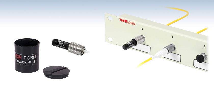
- Improves Return Loss to Better than 50 dB
- Index-Matched Gel Block for Temporary Use
- Light Traps with FC Connectors
FOBH
Fiber Index Matching Block
(Light Trap)
FTFC1
FC/PC Light Trap
Application Idea
An FTFC1 Terminating
Connector is Used to Reduce
Back Reflections from Port A

Please Wait
Thorlabs offers two solutions for fiber optic light trapping: the FOBH Fiber Index Matching Block for temporary applications and Light Traps with FC/PC or FC/APC Connectors. The connector-terminated light traps/terminators are also available in kits together with a selection of fixed fiber attenuators. For free-space beam traps and light-blocking devices, please click here.
| Posted Comments: | |
user
(posted 2024-08-19 17:22:18.87) I would like to ask if FTAPC is used in single mode or multimode or can it be used as long as it is within the wavelength range? jpolaris
(posted 2024-08-19 07:53:41.0) Thank you for contacting Thorlabs. The fiber optic light traps are compatible with single-mode and multimode fibers. Both FTFC1 and FTAPC1 actually incorporate a FG025LJA multimode fiber in their designs. Light is coupled from the input fiber into FG025LJA and is then diffused within the terminator. Yes, you would want to stay within the operating wavelength range of 400 nm - 2100 nm. dayana A
(posted 2019-10-25 22:20:35.13) Please share us the excess loss of FTFC1 and FTAPC1. YLohia
(posted 2019-10-25 11:17:32.0) May I ask what you mean by "excess loss" here? This term is defined as the ratio of the total input power to the total output power and is typically used for multiport devices such as couplers. Since the item in question is a light trap, there is no "output" coming out of the other end. Are you asking how much power is returned to the input fiber? If so, that is specified as the "return loss", which is ≥50 dB. jv
(posted 2015-02-19 17:42:03.26) These are nice, but requires the use of a bulkhead. How about a simple device/cap that slips right over the end of the ferrule? I have often used a solid gel for this function. How about just filling a protective cap with this gel so that when you put it on, it also provides the index match for no reflections.
JV jlow
(posted 2015-02-25 04:50:23.0) Response from Jeremy at Thorlabs: Thank you very much for the suggestion. I have passed this along as a new product idea internally and we will look into implementing this idea. tcohen
(posted 2012-06-20 09:16:00.0) Response from Tim at Thorlabs: It is possible to use our current Fiber Optic Terminators underneath the specified wavelength range but this is not recommended because of the operating wavelength of the fiber. To address this, we are releasing a new terminator incorporating multimode fiber that will increase the operating wavelength. These will be available soon and I will contact you to keep you updated. user
(posted 2012-06-14 16:20:12.0) Can u say a little about the performance outside the specified wavelength range, of special interest is 633 nm. I am using a 2X2 coupler to split my signal but am concerned about the 4th unsed fiber. tcohen
(posted 2012-05-03 12:56:00.0) Response from Tim at Thorlabs: Thank you for contacting us. As a guideline, we recommend not exceeding 300mW CW for these terminators. makarov
(posted 2012-05-02 04:11:45.0) What is the maximum optical power rating for these terminators? |

Click to Enlarge
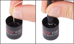
Figure G1.1 Inserting Fiber into the FOBH Index Matching Block / Light Trap
- Light Trap for Temporarily Coupling Light Out of Bare Fiber or Fiber Connectors
- Index Matched to Standard Silica Fiber Core (n = 1.46)
- Return Loss: ≥50 dB (Typical @ 1550 nm)
- Max Optical Power: 100 mW
- Solid Gel Contained within Black Canister with Cap
Thorlabs' FOBH Fiber Index Matching Block is a light trap that provides a temporary method for coupling the light out of optical fiber without the use of any connectors or attachments. The vial contains a resilient, dry optical gel that is index matched (n = 1.46) to the core of standard silica optical fiber. While the fiber is pressed against the surface of the gel material, the light is coupled into the gel and is then scattered and absorbed by the black vial. By placing the end of the fiber in firm contact with the surface of the gel, reflections from the end of single mode fiber are reduced to better than 50 dB in most cases.
The FOBH Light Trap is designed for use at visible and infrared wavelengths and has been tested at 635 - 1550 nm. Any type of fiber that has an exposed end face can be used. This includes the use of bare fibers, as well as those that are connectorized with a polished ferrule of any diameter. Glass rods and multimode fibers can also be used, but performance may be reduced. Fiber bundles can also be terminated if all surfaces make good contact.
To use the FOBH Light Trap, hold the fiber or connector and press the end firmly onto the surface of the gel so that it makes good contact. Do not press hard enough to break the gel surface or embed the fiber into the surface. It is important that both the end of the fiber and the surface it touches are perfectly clean, otherwise there will be scattered light that returns up the fiber, reducing the return loss. Improved results may be obtained by cleaning the fiber and light trap surfaces, as well as by avoiding the direct center of the vial and making contact closer to the walls of the vial. The surface of the index-matched gel can be cleaned with alcohol and a soft, lint-free swab.
We also offer Index Matching Gel for reducing signal loss when coupling two fibers together.

| Item # | FTFC1 | FTAPC1 |
|---|---|---|
| Return Loss | ≥50 dB | |
| Wavelength Range | 400 - 2100 nm | |
| Input Power (Max) | 300 mW at 1550 nm, CW | |
| Fiber Type | FG025LJA | |
| Connector Type | FC/PC | FC/APC |
Click to Enlarge
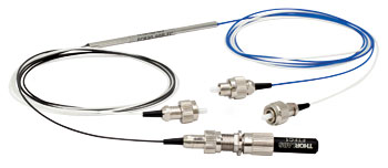
Figure G2.1 2 x 2 SM Coupler Converted to a 1 x 2 Coupler Using
ADAFC1 FC/PC Mating Coupler and FTFC1 Light Trap
- Improves Return Loss to Better than 50 dB
- FC/PC or FC/APC Connector
- Wavelength Range: 400 - 2100 nm
- Available in Kits with a Selection of Fixed Fiber Attenuators (See Below for Details)
Thorlabs' Terminating Fiber Light Trap Connectors are designed to be used with ports that do not have an output fiber connected to them. Terminating connectors reduce back reflections into the input fiber by up to 50 dB by coupling emitted light into FG025LJA fiber and then diffusing the light within the terminator. In contrast, typical back reflections from an unused port can be as poor as 20 dB. Our terminators are for use with light from 400 - 2100 nm, and have male, FC/PC or FC/APC, 2.0 mm narrow key connectors.
Figure G2.1 shows an FTPC1 fiber optic terminator being used to convert a 2x2 SM fiber coupler into a 1x2 coupler. Here, the FTFC1 is connected to the coupler using an ADAFC1 mating sleeve. Thorlabs offers a range of fiber optic couplers, including 2x2 SM couplers.

| Table G3.1 FAK03 FC/PC Attenuator Kit | Table G3.2 FAK05 FC/APC Attenuator Kit | ||
|---|---|---|---|
| Item | Qty.a | Item | Qty.a |
| Fixed Fiber Optic Attenuatorsb | Fixed Fiber Optic Attenuatorsb | ||
| 3 dB, FC/PC (FA03T) | 1 | 3 dB, FC/APC (FA03T-APC) | 1 |
| 5 dB, FC/PC (FA05T) | 1 | 5 dB, FC/APC (FA05T-APC) | 1 |
| 10 dB, FC/PC (FA10T) | 1 | 10 dB, FC/APC (FA10T-APC) | 1 |
| 15 dB, FC/PC (FA15T) | 1 | 15 dB, FC/APC (FA15T-APC) | 1 |
| 20 dB, FC/PC (FA20T) | 1 | 20 dB, FC/APC (FA20T-APC) | 1 |
| 25 dB, FC/PC (FA25T) | 1 | 25 dB, FC/APC (FA25T-APC) | 1 |
| Fiber Optic Terminator / Light Trapc | Fiber Optic Terminator / Light Trapc | ||
| FC/PC Connector (FTFC1) | 5 | FC/APC Connector (FTAPC1) | 5 |
| Dust Caps | Dust Caps | ||
| Female, White | 12 | Female, Green | 12 |
| Male, Clear | 25 | Male, Green | 25 |
- Six Fixed Fiber Optic Attenuators for 1240 - 1620 nm with Attenuation Values Ranging from 3 to 25 dB
- Five Fiber Optic Terminators / Light Traps for Use in the 400 - 2100 nm Wavelength Range
- Additional 12 Female and 25 Male Dust Caps Included for Convenience
- Versions Available with FC/PC or FC/APC Connectors
- Packaged in a Compact Plastic Box with Nine Compartments
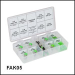
Thorlabs' Fiber Optic Attenuator and Terminator Kits each contain six fixed attenuators, five terminators, and a selection of dust caps. Components in the FAK03 kit have FC/PC connectors while those in the FAK05 kit have FC/APC connectors. Each kit is packaged in a plastic box measuring 7.0" x 3.5" x 1.25" (177.8 mm x 88.9 mm x 31.8 mm) and has nine labeled compartments. The label on the lid indicates the contents, associated Thorlabs item number (where applicable), attenuation value and tolerance for the attenuators, and wavelength range and return loss for the terminators. Tables G3.1 and G3.2 list the description and quantity of each item included in these kits.
 Products Home


 Zoom
Zoom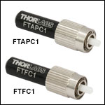
 Fiber Optic Light Traps / Terminators