 Products Home / Imaging Components / DIY Cerna Components: Imaging for Home Builders / Objective Mounting for DIY Cerna® Systems
Objective Mounting for DIY Cerna® Systems

- Single- and Dual-Objective Holders
- Focusing Modules with 1" Travel Range
- Piezo Objective Scanner for High-Speed Z-Stack Acquisition
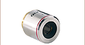
CSN100
Single-Objective Nosepiece
PFM450E
Piezo Objective Scanner
(Controller Included)
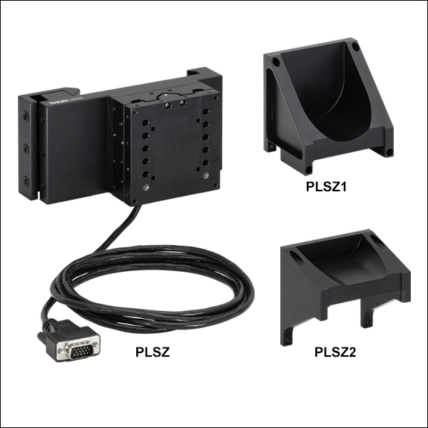
PLSZ
Motorized Focusing Module
CSN210
Motorized, Dual-Objective Nosepiece
Application Idea
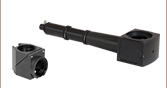
A CSN1202 Manual Retracting, Dual-Objective Nosepiece is Shown with Two Objectives Mounted
CSNK100
Single-Objective Nosepiece with Magnetic Removable Objective Mount
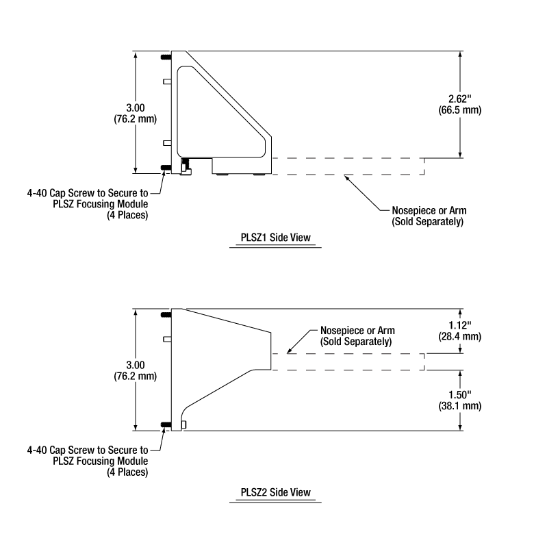
PLSZ1
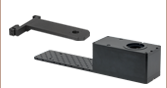
Angle Bracket for Edge-Mounted Arms


Please Wait
Click to Enlarge
This system uses our CSN200
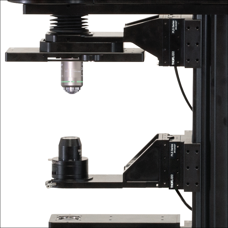
Dual-Objective Nosepiece, BSA2000 Condenser Arm, and two PLSZ focusing modules with PLSZ1 and PLSZ2 angle brackets to mount and motorize a condenser and objective, respectively.
Features
- Place Objectives at 7.74" Throat Depth of DIY Cerna® Microscope
- Variety of Threads for Objective Mounting
- Nosepieces for 1 or 2 Objectives:
- Fixed, D1T Dovetail, and Kinematic Single-Objective Nosepieces
- Single- and Dual-Objective Nosepieces with Slots for Differential Interference Contrast (DIC) Objective Prisms
- Sliding and Retracting Dual-Objective Nosepieces
- Motorized, Dual-Objective Nosepiece for Easy Objective Changing Available
- Piezo-Actuated Objective Scanner for High-Frame-Rate Z-Stack Acquisition
- Adapters (Sold Separately) Support a Variety of Standard Microscope and Objective Threads
- Macro Lens Nosepiece with Internal SM2 (2.035"-40) Threads
- 60 mm Cage System Compatibility on Select Nosepieces
- Motorized Focusing Module with 1" of Z-Travel Secure Nosepieces to Microscope Body
- Adapter for Integration of Nikon Eclipse Ti2 Nosepieces with Cerna Systems
Click to Enlarge
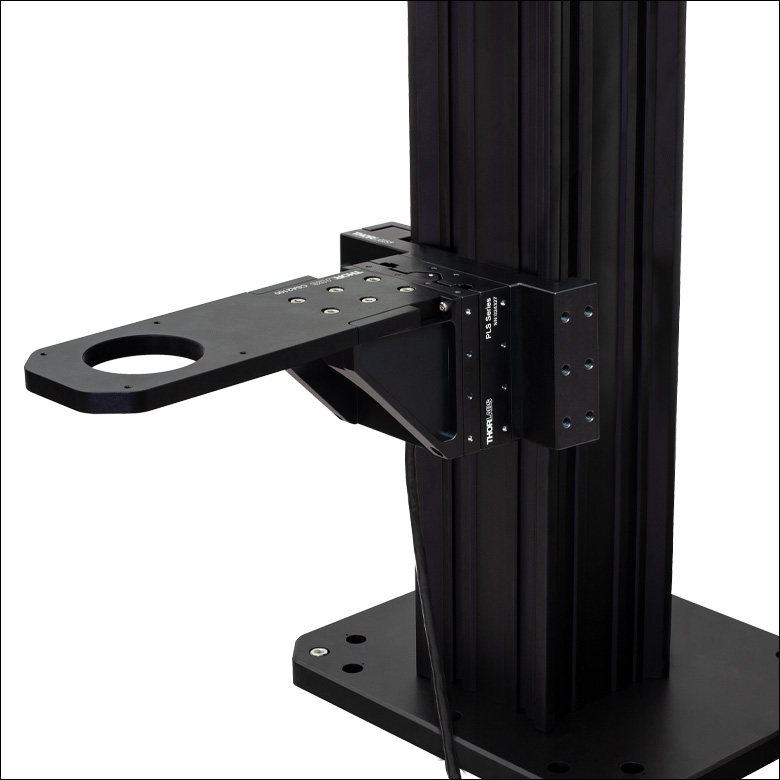
A PLSZ Motorized Focusing Module with a PLSZ1 Angle Bracket and Condenser Arm Mounted to a Microscope Body
Thorlabs' selection of objective holders provides a variety of mechanical interfaces for mounting microscope objectives and other optical elements along the optical path of a DIY Cerna system. Our current offering includes single- and dual-objective nosepieces. We offer single-objective mounts with 60 mm cage system compatibility, one with a slim profile and one with a magnetic removable mount. We also offer a single-objective nosepiece with a D1T dovetail and both 30 mm and 60 mm cage compatibility. We have single-objective and dual-objective nosepieces that have slots for DIC objective prisms, as well as a motorized, dual-objective nosepiece with a precision servo motor. In addition, we manufacture a nosepiece with internal SM2 (2.035"-40) threads and taps for a 60 mm cage system, which can be used to mount macro lenses and a wide variety of Thorlabs optomechanics.
Thorlabs also offers the PLSZ motorized fine focusing module (available below), which provide 1" of travel along the Z axis and connects objective nosepieces and arms to the microscope body using angle brackets (sold separately). The PLSZ1 and PLSZ2 angle brackets facilitate flexibility in the mounting configuration. The PLSZ module can be driven using the MCM301 3-Axis Controller (sold separately).
A nosepiece adapter is also available, which allows for Nikon Eclipse Ti2 nosepieces to be attached to Cerna nosepieces and mounting arms with 60 mm cage system compatiblity.
Additional body attachments and extensions are available which allow the integration of Thorlabs' lens tube systems, cage construction systems, and other optomechanics with our Cerna microscopy platform. We also offer condenser arms that are designed to mount condensers at the 7.74" throat depth of DIY Cerna systems. For optics that do not require frequent adjustment, we also offer fixed mounting arms that mount lens tubes and cage systems directly along the optical path of the microscope.
| Thorlabs Dovetail Referencea | |||
|---|---|---|---|
| Type | Shape | Outer Dimension | Angle |
| 95 mm | Linear | 95 mm | 45° |
| D1N | Circular | Ø2.018" | 60° |
| D2Nb | Circular | Ø1.50" | 90° |
| D2NBb | Circular | Ø1.50" | 90° |
| D3N | Circular | Ø45 mm | 70° |
| D5N | Circular | Ø1.58" | 90° |
| D6N | Circular | Ø1.90" | 90° |
| D7N | Circular | Ø2.05" | 90° |
| D1T | Circular | Ø1.50" | 60° |
| D3T | Circular | Ø1.65" | 90° |
| D1Y | Circular | Ø107 mm | 60° |
| D2Y | Circular | Ø2.32" | 50° |
| D3Y | Circular | Ø1.75" | 90° |
| D4Y | Circular | Ø56 mm | 60° |
| D5Y | Circular | Ø46 mm | 60° |
| D6Y | Circular | Ø41.9 mm | 45° |
| D1Z | Circular | Ø54 mm | 60° |
| D2Z | Circular | Ø57 mm | 60° |
| D3Z | Circular | Ø54 mm | 45° |
Click to Enlarge
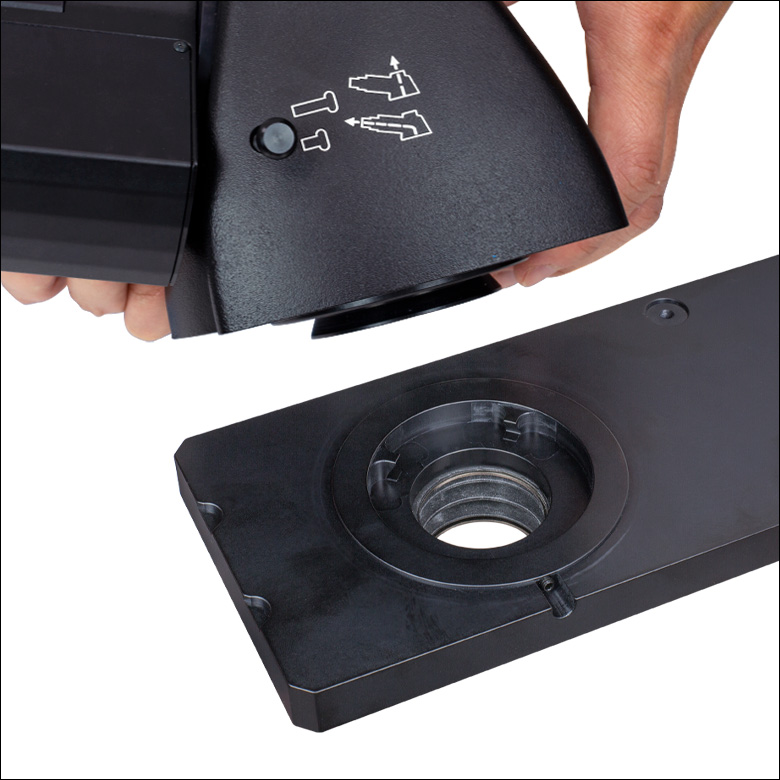
This photo shows the male D1N dovetail on the trinoculars next to the female D1N dovetail on the epi-illumination arm.

Click to Enlarge
This photo shows the male 95 mm dovetail on the microscope body and the female 95 mm dovetail on the CSA1002 Fixed Arm.
Introduction to Microscope Dovetails
Dovetails are used for mechanical mating and optical port alignment of microscope components. Components are connected by inserting one dovetail into another, then tightening one or more locking setscrews on the female dovetail. Dovetails come in two shapes: linear and circular. Linear dovetails allow the mating components to slide before being locked down, providing flexible positioning options while limiting unneeded degrees of freedom. Circular dovetails align optical ports on different components, maintaining a single optical axis with minimal user intervention.
Thorlabs manufactures many components which use dovetails to mate with our own components or those of other manufacturers. To make it easier to identify dovetail compatibility, we have developed a set of dovetail designations. The naming convention of these designations is used only by Thorlabs and not other microscope manufacturers. The table to the right lists all the dovetails Thorlabs makes, along with their key dimensions.
In the case of Thorlabs’ Cerna® microscopes, different dovetail types are used on different sections of the microscope to ensure that only compatible components can be mated. For example, our WFA2002 Epi-Illuminator Module has a male D1N dovetail that mates with the female D1N dovetail on the microscope body's epi-illumination arm, while the CSS2001 XY Microscopy Stage has a female D1Y dovetail that mates with the male D1Y dovetail on the CSA1051 Mounting Arm.
To learn which dovetail type(s) are on a particular component, consult its mechanical drawing, available by clicking on the red Docs icon ( ) below. For adapters with a female dovetail, the drawing also indicates the size of the hex key needed for the locking setscrew(s). It is important to note that mechanical compatibility does not ensure optical compatibility. Information on optical compatibility is available from Thorlabs' web presentations.
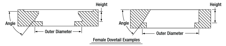
For customers interested in machining their own dovetails, the table to the right gives the outer diameter and angle (as defined by the drawings below) of each Thorlabs dovetail designation. However, the dovetail's height must be determined by the user, and for circular dovetails, the user must also determine the inner diameter and bore diameter. These quantities can vary for dovetails of the same type. One can use the intended mating part to verify compatibility.
In order to reduce wear and simplify connections, dovetails are often machined with chamfers, recesses, and other mechanical features. Some examples of these variations are shown by the drawings below.

Click to Enlarge
Two examples of how circular male dovetails can be manufactured.
Click to Enlarge
Two examples of how circular female dovetails can be manufactured.
Standard Mechanical Interfaces on DIY Cerna® Components
The table below gives the dovetail, optical component threads, and cage system interfaces that are present on each DIY Cerna component. If a DIY Cerna component does not have one of the standard interfaces in the table, it is not listed here. Please note that mechanical compatibility does not ensure optical compatibility. Information on optical compatibility is available from Thorlabs' web presentations.
| Item # | Microscope Dovetails | Optical Component Threadsa | Cage Systemsb | ||||||||||
|---|---|---|---|---|---|---|---|---|---|---|---|---|---|
| 95 mm | D1N | D2N | D2NB | D3N | D5N | D1T | D3T | D1Y | D5Y | Internal | External | ||
| 2CM1 | - | - | - | - | - | - | - | - | - | - | SM1c (1.035"-40) and SM2d (2.035"-40) | SM1c (1.035"-40) | 60 mmd |
| 2CM2 | - | - | - | - | - | - | - | - | - | - | SM1c (1.035"-40) and SM2d (2.035"-40) | SM1c (1.035"-40) | 30 mmc |
| BSA2000e | - | - | - | - | Female | - | - | - | - | - | - | - | - |
| CEA1350 | Male | Female | - | - | - | - | - | - | - | - | - | - | 60 mmd |
| CEA1400 | Male | Female | - | - | - | - | - | - | - | - | - | - | 60 mmd |
| CEA1500 | Male | Female | - | - | - | - | - | - | - | - | - | - | 60 mmd |
| CEA1600 | Male | Female | - | - | - | - | - | - | - | - | - | - | 60 mmd |
| CFB1500 | Male | - | - | - | - | - | - | - | - | - | - | - | - |
| CSA1000 | Female | - | - | - | - | - | - | - | - | - | - | - | - |
| CSA1001 | Female | - | - | - | - | - | - | - | - | - | SM1c (1.035"-40) | - | 30 mmc |
| CSA1002 | Female | - | - | - | - | - | - | - | - | - | SM2d (2.035"-40) | - | 60 mmd |
| CSA1003 | - | Female | - | - | - | - | - | - | - | - | - | - | 60 mmd |
| CSA1051 | Female | - | - | - | - | - | - | - | Male | - | - | - | - |
| CSA1200e,f | - | - | - | - | - | - | - | - | - | - | - | - | 60 mmd |
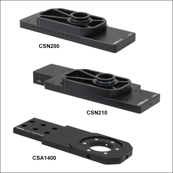
| CSA1400e | - | - | - | - | - | - | Female | - | - | - | - | - | 60 mmd |
| CSA1500e,g | - | - | - | - | - | - | - | - | - | - | - | - | - |
| CSA2000e | - | - | - | - | Female | - | - | - | - | - | SM2d (2.035"-40) | - | 60 mmd |
| CSA2001 | - | - | - | - | Female | - | - | - | - | - | - | SM2d (2.035"-40) | - |
| CSA2100e | - | - | - | - | - | - | - | - | - | - | SM2d (2.035"-40) | - | 60 mmd |
| CSA3000(/M) | - | Male | - | - | - | - | - | - | - | - | - | - | - |
| CSA3010(/M) | - | Male | - | - | - | - | - | - | - | - | - | - | 30 mmc and 60 mmd |
| Item # | 95 mm | D1N | D2N | D2NB | D3N | D5N | D1T | D3T | D1Y | D5Y | Internal | External | Cage Systems |
| CSC1001 | - | - | - | - | Male | - | - | - | - | - | - | - | - |
| CSC1002 | - | - | - | - | Male | - | - | - | - | - | - | - | - |
| CSC2001 | - | - | - | - | Male | - | - | - | - | - | - | - | - |
| CSD1001 | - | Male & Female | - | Female | - | - | - | - | - | - | - | - | - |
| CSD1002 | - | Male & Female | - | - | - | - | - | - | - | - | - | C-Mounth | - |
| CSE2000 | - | Male & Female | - | - | - | - | - | - | - | - | - | - | 60 mmd |
| CSE2100 | - | Male & Female | - | - | - | - | - | Female | - | - | SM1c (1.035"-40) | - | 30 mmc and 60 mmd |
| CSE2200 | - | Male & Female | - | - | - | - | - | Female | - | - | SM1c (1.035"-40) | - | 30 mmc and 60 mmd |
| CSN100e | - | - | - | - | - | - | - | - | - | - | M32 x 0.75 | - | 60 mmd |
| CSN110 | - | - | - | - | - | - | Male | - | - | - | M32 x 0.75 | - | 30 mmc and 60 mmd |
| CSNK10 | - | - | - | - | - | - | - | - | - | - | M32 x 0.75 | - | 60 mmd |
| CSNK100e | - | - | - | - | - | - | - | - | - | - | M32 x 0.75 | - | 60 mmd |
| CSN200 | - | - | - | - | - | - | Male | - | - | - | M32 x 0.75 | - | - |
| CSN210 | - | - | - | - | - | - | Male | - | - | - | M32 x 0.75 | - | - |
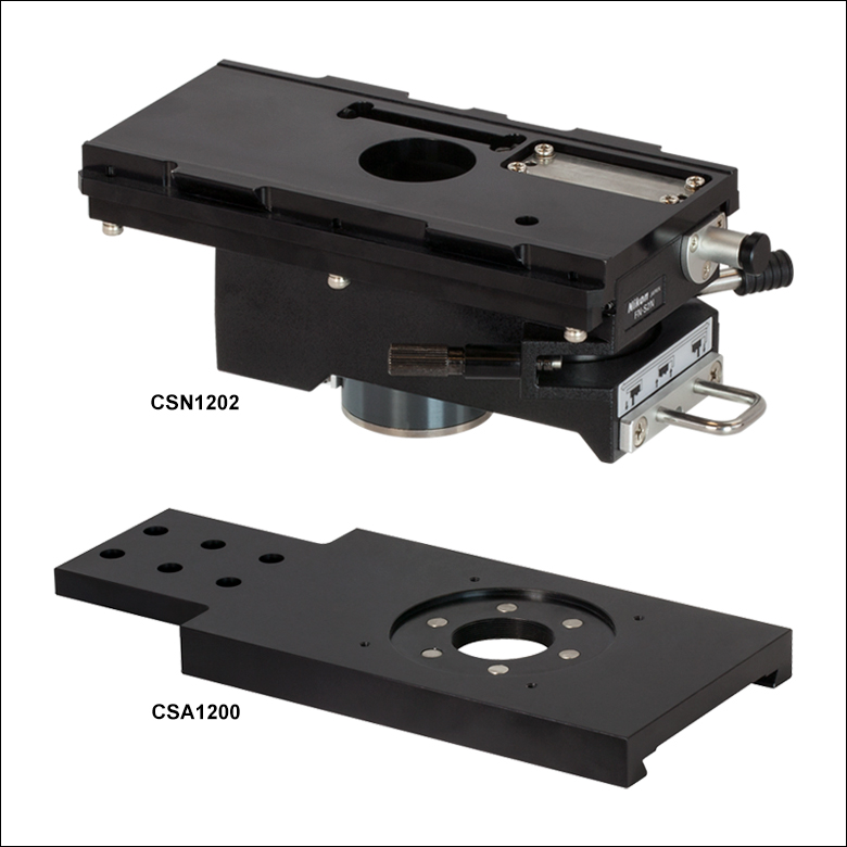
| CSN1201f | - | - | - | - | - | - | - | - | - | - | M32 x 0.75 | - | - |
| CSN1202f | - | - | - | - | - | - | - | - | - | - | M25 x 0.75 | - | - |
| CSS2001 | - | - | - | - | - | - | - | - | Female | - | - | - | - |
| LAURE1 | - | Male | Female | - | - | - | - | - | - | - | - | - | - |
| LAURE2 | - | Male | Female | - | - | - | - | - | - | - | - | - | - |
| LCPN1 | - | - | - | - | Male | - | - | - | - | - | SM30 (M30.5 x 0.5) | - | 30 mmc and 60 mmd |
| LCPN2 | - | Male | - | - | - | - | - | - | - | - | SM30 (M30.5 x 0.5) | - | 30 mmc and 60 mmd |
| Item # | 95 mm | D1N | D2N | D2NB | D3N | D5N | D1T | D3T | D1Y | D5Y | Internal | External | Cage Systems |
| LCPN3 | - | Male | - | - | - | - | - | - | - | Female | SM30 (M30.5 x 0.5) | - | 60 mmd |
| LCPN4 | - | Male | - | - | - | - | - | - | - | - | SM2d (2.035"-40) | - | 60 mmd |
| LCPN5 | - | - | - | - | Male | - | - | - | - | - | SM2d (2.035"-40) | - | 60 mmd |
| LCPN6 | - | - | Female | - | - | - | - | - | - | - | SM1c (1.035"-40) | - | 30 mmc and 60 mmd |
| LCPY2 | - | - | - | - | - | - | - | - | - | Male | SM30 (M30.5 x 0.5) | - | 30 mmc and 60 mmd |
| LCPY3 | - | - | - | - | - | - | - | - | - | Female | - | - | 30 mmc and 60 mmd |
| OPX2400(/M) | - | Male & Female | - | - | - | - | - | - | - | - | SM2d (2.035"-40) | - | 60 mmd |
| SM1A70 | - | - | - | - | - | - | - | - | - | - | SM30 (M30.5 x 0.5) | SM1c (1.035"-40) | - |
| SM1A58 | - | - | Male | Male | - | - | - | - | - | - | SM1c (1.035"-40) | SM2d (2.035"-40) | 30 mmc |
| SM2A56 | - | - | - | - | - | - | - | Male | - | - | - | SM2d (2.035"-40) | - |
| SM2A59 | - | Male | - | - | - | - | - | - | - | - | SM2d (2.035"-40) | - | - |
| TC1X | - | - | Male | - | - | - | - | - | - | - | - | - | - |
| WFA0150 | Female | - | - | - | - | - | - | - | - | - | - | - | - |
| WFA1000 | - | - | - | - | - | - | - | - | - | - | - | - | 30 mmc |
| WFA1010 | - | - | - | - | - | - | - | - | - | - | SM1c (1.035"-40) | - | 30 mmc |
| WFA1020 | - | - | - | - | - | - | - | - | - | - | SM1c (1.035"-40) | - | 30 mmc |
| WFA1051 | - | - | - | - | - | - | - | - | - | - | SM1c (1.035"-40) | - | 30 mmc |
| WFA1100 | - | - | - | - | - | - | - | - | - | - | - | - | 30 mmc |
| WFA2001 | - | Male & Female | - | - | - | - | - | - | - | - | SM1c (1.035"-40) | SM1c (1.035"-40) | - |
| WFA2002 | - | Male & Female | - | - | - | - | - | - | - | - | SM1c (1.035"-40) | - | 30 mmc |
| Item # | 95 mm | D1N | D2N | D2NB | D3N | D5N | D1T | D3T | D1Y | D5Y | Internal | External | Cage Systems |
| WFA4100 | - | Male | - | - | - | - | - | - | - | - | SM1c (1.035"-40) | C-Mounth | - |
| WFA4101 | - | Male | - | - | - | - | - | - | - | - | SM1c (1.035"-40) | C-Mounth | - |
| WFA4102 | - | Male | - | - | - | - | - | - | - | - | SM1c (1.035"-40) | C-Mounth | - |
| WFA4111 | - | Male | - | - | - | - | - | - | - | - | - | SM2d (2.035"-40) | - |
| WFA4112 | - | - | - | Male | - | - | - | - | - | - | - | C-Mounth | - |
| Female | - | - | - | - | - | - | - | - | - | - | - | - | |
| Female | - | - | - | - | - | - | - | - | - | - | - | - | |
| Female | - | - | - | - | - | - | - | - | - | - | - | - | |
| Female | - | - | - | - | - | - | - | - | - | - | - | - | |
| XT95P12(/M) | Female | - | - | - | - | - | - | - | - | - | - | - | - |
| ZFM1020 | Female | - | - | - | - | - | - | - | - | - | - | - | - |
| ZFM1030 | Female | - | - | - | - | - | - | - | - | - | - | - | - |
| ZFM2020 | Female | - | - | - | - | - | - | - | - | - | - | - | - |
| ZFM2030 | Female | - | - | - | - | - | - | - | - | - | - | - | - |
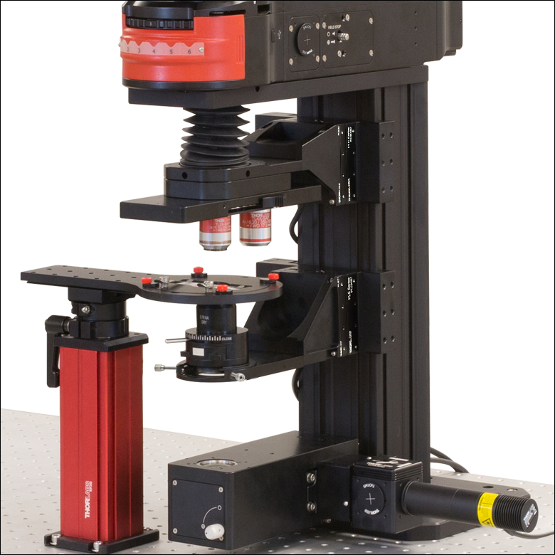
Building a Cerna® Microscope
The Cerna microscopy platform's large working volume and system of dovetails make it straightforward to connect and position the components of the microscope. This flexibility enables simple and stable set up of a preconfigured microscope, and provides easy paths for later upgrades and modification. See below for a couple examples of the assembly of some DIY Cerna microscopes.
DIY Cerna Design and Assembly
Walkthrough of a DIY Microscope Configuration
This DIY microscope uses a CSA3000(/M) Breadboard Top, a CSA2001 Dovetail Adapter, our CSA1001 and CSA1002 Fixed Arms, and other body attachments and extensions. These components provide interfaces to our lens tube and cage construction systems, allowing the rig to incorporate two independent trans-illumination modules, a home-built epi-illumination path, and a custom sample viewing optical path.
The simplicity of Thorlabs optomechanical interfaces allows a custom DIY microscope to be quickly assembled and reconfigured for custom imaging applications.
| Posted Comments: | |
王 卓
(posted 2021-09-09 21:15:13.767) can i buy the objective lens turrets (csn510) now? YLohia
(posted 2021-09-09 03:37:33.0) Hello, thank you for contacting Thorlabs. The CSN510 has been temporarily discontinued due to production issues. In the mean time, we recommend the OT1 objective lens turret as an alternative. Michael Gerlt
(posted 2020-08-19 06:37:26.31) Dear Thorlabs Team,
I am working in Prof. Duals Lab at ETH and we are a heavy user of Thorlabs CERNA components. It was a great idea to design a microscope such that it is highly customizable! We bought different variants such that it fits our needs for our individual projects. In total we have 3 CERNA microscope now that can do all kind of things 😉 Lately, we were seeking for a low budget version. The by far most costly thing is the control Nob MCM3001 and the motorized stages ZFM2020 + PLS-XY. PLS-XY can be easily replaced by another xy stage. However, there is no proper solution to replace the ZFM2020. Could you please add an option in your catalogue with a proper manual focus range and the ability to determine the focus exactly?
All the best,
Michael YLohia
(posted 2020-08-19 01:44:50.0) Dear Michael, thank you for your feedback. We're always interested in hearing about our customers' thoughts on our products and gaps in our current catalog. At the moment, we only offer the ZFM1020/ZFM1030 manual focus modules, which are relatively coarse. We hope to offer a finer manual focus module in the future. user
(posted 2020-03-15 02:34:37.643) Hi Thorlabs Team,
I was wondering if it would be possible for you to add an optional manual focus drive to the Cerna scope series. For patch-clamp experiments, in which we often switch between fine and coarse focus in Z, I’d appreciate the simplicity of a manual drive.
Many thanks!
J
Ps. It would also be great if my message didn’t disappear if I have a type in the security code... YLohia
(posted 2020-03-16 10:52:05.0) Hello, thank you for your feedback. I have posted your request on our internal engineering forum for further consideration as a future product. user
(posted 2020-03-05 13:00:46.377) Dear Sir/Madam,
we are using the Cerna Microscope System in the lab, but it would be great to have better manual control over the focus of the objective... I have also talked to colleagues, that feel the same way. Otherwise, keep up the great work!
Cheers,
Bernhard llamb
(posted 2020-03-09 03:47:22.0) Hello Bernhard, thank you for your feedback. Similar to Manuel's feedback below, we will be sure to consider a manually controlled focusing module. I see that you did not leave any contact information, so feel free to reach out to TechSupport@thorlabs.com if you have any further feedback or questions. Manuel Engelmayer
(posted 2020-03-03 05:16:29.627) Hi,
it would be really helpful to have a proper way to manually adjust a stage at a microscope body in both coarse and fine ways.
Basically the standard way to adjust the focus on most standard microscopes (The two knobs on the side of a optical microscope for coarse and fine adjustment).
I'm currently trying to get a CERNA-System, where I do not plan to scan across the sample (so no motorization needed), but where I have to exactly set the focus. Buying a motorized stage would work, but it's really expensive with controllers, if you basically just want to adjust a single dimension a few microns.
If you have any questions, don't hesitate to contact me. Otherwise I'm already in contact with one of your colleagues bypassing that issue.
Thanks and best wishes
Manuel llamb
(posted 2020-03-05 07:24:31.0) Hello Manuel, thank you for your feedback regarding a manual fine focusing module for our Cerna systems. I have added your request to our internal product forum for further review, and am glad to hear you have found a suitable alternative in the meantime. srubin
(posted 2018-08-28 09:24:17.71) Can CSN500 and CSN510 be used in a standard opto mech setup (not Cerna). Does it have lens tube or cage interfaces? YLohia
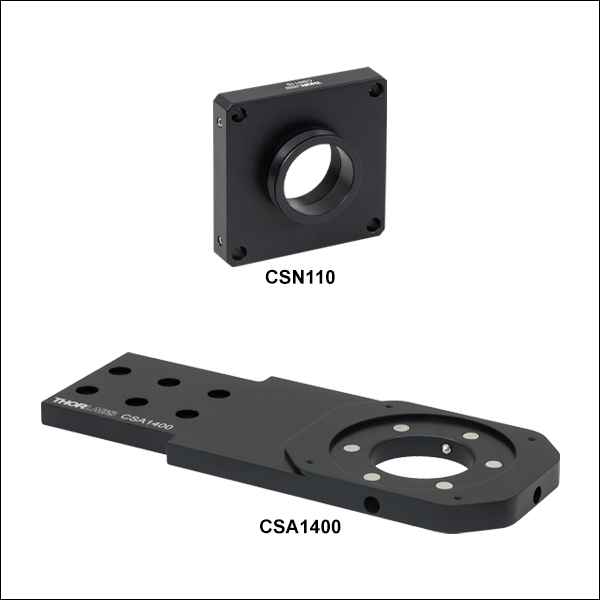
(posted 2018-08-28 11:09:12.0) Hello, the CSN500 and CSN510 can indeed be used with standard Thorlabs opto-mech by implementing the CSA1400 mounting arm, which has 60mm cage #4-40 thru holes (for cage system use) as well as M6 counterbores for additional mounting options. m.c.ashby
(posted 2018-03-22 13:14:53.533) Do you have any information on the precision of the centering of the objectives when switching between positions on CSN1301? YLohia
(posted 2018-03-30 04:04:56.0) Hello, thank you for contacting Thorlabs. Unfortunately, we have yet to do more conclusive testing in order to spec the precision/repeatability of centering the CSN1301 when switching between the positions. We hope to have this information available in the future. |
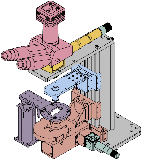
Click on the different parts of the microscope to explore their functions.
Elements of a Microscope
This overview was developed to provide a general understanding of a Cerna® microscope. Click on the different portions of the microscope graphic to the right or use the links below to learn how a Cerna microscope visualizes a sample.
Terminology
Arm: Holds components in the optical path of the microscope.
Bayonet Mount: A form of mechanical attachment with tabs on the male end that fit into L-shaped slots on the female end.
Bellows: A tube with accordion-shaped rubber sides for a flexible, light-tight extension between the microscope body and the objective.
Breadboard: A flat structure with regularly spaced tapped holes for DIY construction.
Dovetail: A form of mechanical attachment for many microscopy components. A linear dovetail allows flexible positioning along one dimension before being locked down, while a circular dovetail secures the component in one position. See the Microscope Dovetails tab or here for details.
Epi-Illumination: Illumination on the same side of the sample as the viewing apparatus. Epi-fluorescence, reflected light, and confocal microscopy are some examples of imaging modalities that utilize epi-illumination.
Filter Cube: A cube that holds filters and other optical elements at the correct orientations for microscopy. For example, filter cubes are essential for fluorescence microscopy and reflected light microscopy.
Köhler Illumination: A method of illumination that utilizes various optical elements to defocus and flatten the intensity of light across the field of view in the sample plane. A condenser and light collimator are necessary for this technique.
Nosepiece: A type of arm used to hold the microscope objective in the optical path of the microscope.
Optical Path: The path light follows through the microscope.
Rail Height: The height of the support rail of the microscope body.
Throat Depth: The distance from the vertical portion of the optical path to the edge of the support rail of the microscope body. The size of the throat depth, along with the working height, determine the working space available for microscopy.
Trans-Illumination: Illumination on the opposite side of the sample as the viewing apparatus. Brightfield, differential interference contrast (DIC), Dodt gradient contrast, and darkfield microscopy are some examples of imaging modalities that utilize trans-illumination.
Working Height: The height of the support rail of the microscope body plus the height of the base. The size of the working height, along with the throat depth, determine the working space available for microscopy.
 Click to Enlarge
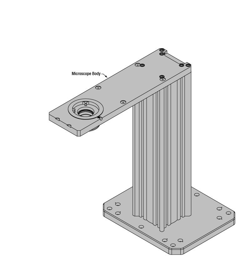
Cerna Microscope Body
Click to Enlarge
Body Details
Microscope Body
The microscope body provides the foundation of any Cerna microscope. The support rail utilizes 95 mm rails machined to a high angular tolerance to ensure an aligned optical path and perpendicularity with the optical table. The support rail height chosen (350 - 600 mm) determines the vertical range available for experiments and microscopy components. The 7.74" throat depth, or distance from the optical path to the support rail, provides a large working space for experiments. Components attach to the body by way of either a linear dovetail on the support rail, or a circular dovetail on the epi-illumination arm (on certain models). Please see the Microscope Dovetails tab or here for further details.
 Click to Enlarge
Illumination with a Cerna microscope can come from above (yellow) or below (orange). Illumination sources (green) attach to either.
Illumination
Using the Cerna microscope body, a sample can be illuminated in two directions: from above (epi-illumination, see yellow components to the right) or from below (trans-illumination, see orange components to the right).
Epi-illumination illuminates on the same side of the sample as the viewing apparatus; therefore, the light from the illumination source (green) and the light from the sample plane share a portion of the optical path. It is used in fluorescence, confocal, and reflected light microscopy. Epi-illumination modules, which direct and condition light along the optical path, are attached to the epi-illumination arm of the microscope body via a circular D1N dovetail (see the Microscope Dovetails tab or here for details). Multiple epi-illumination modules are available, as well as breadboard tops, which have regularly spaced tapped holes for custom designs.
Trans-illumination illuminates from the opposite side of the sample as the viewing apparatus. Example imaging modalities include brightfield, differential interference contrast (DIC), Dodt gradient contrast, oblique, and darkfield microscopy. Trans-illumination modules, which condition light (on certain models) and direct it along the optical path, are attached to the support rail of the microscope body via a linear dovetail (see Microscope Dovetails tab or here). Please note that certain imaging modalities will require additional optics to alter the properties of the beam; these optics may be easily incorporated in the optical path via lens tubes and cage systems. In addition, Thorlabs offers condensers, which reshape input collimated light to help create optimal Köhler illumination. These attach to a mounting arm, which holds the condenser at the throat depth, or the distance from the optical path to the support rail. The arm attaches to a focusing module, used for aligning the condenser with respect to the sample and trans-illumination module.
 |
 |
 |
 |
 |
 |
 |
 |
| Epi-Illumination Modules | Breadboards & Body Attachments |
Brightfield | DIC | Dodt | Condensers | Condenser Mounting | Light Sources |
 Click to Enlarge
Light from the sample plane is collected through an objective (blue) and viewed using trinocs or other optical ports (pink).
Sample Viewing/Recording
Once illuminated, examining a sample with a microscope requires both focusing on the sample plane (see blue components to the right) and visualizing the resulting image (see pink components).
A microscope objective collects and magnifies light from the sample plane for imaging. On the Cerna microscope, the objective is threaded onto a nosepiece, which holds the objective at the throat depth, or the distance from the optical path to the support rail of the microscope body. This nosepiece is secured to a motorized focusing module, used for focusing the objective as well as for moving it out of the way for sample handling. To ensure a light-tight path from the objective, the microscope body comes with a bellows (not pictured).
Various modules are available for sample viewing and data collection. Trinoculars have three points of vision to view the sample directly as well as with a camera. Double camera ports redirect or split the optical path among two viewing channels. Camera tubes increase or decrease the image magnification. For data collection, Thorlabs offers both cameras and photomultiplier tubes (PMTs), the latter being necessary to detect fluorescence signals for confocal microscopy. Breadboard tops provide functionality for custom-designed data collection setups. Modules are attached to the microscope body via a circular dovetail (see the Microscope Dovetails tab or here for details).


 Click to Enlarge
The rigid stand (purple) pictured is one of various sample mounting options available.
Sample/Experiment Mounting
Various sample and equipment mounting options are available to take advantage of the large working space of this microscope system. Large samples and ancillary equipment can be mounted via mounting platforms, which fit around the microscope body and utilize a breadboard design with regularly spaced tapped through holes. Small samples can be mounted on rigid stands (for example, see the purple component to the right), which have holders for different methods of sample preparation and data collection, such as slides, well plates, and petri dishes. For more traditional sample mounting, slides can also be mounted directly onto the microscope body via a manual XY stage. The rigid stands can translate by way of motorized stages (sold separately), while the mounting platforms contain built-in mechanics for motorized or manual translation. Rigid stands can also be mounted on top of the mounting platforms for independent and synchronized movement of multiple instruments, if you are interested in performing experiments simultaneously during microscopy.
 |
 |
 |
 |
 |
| Translating Platforms | Rigid Stands | Translation Stages for Rigid Stands | Motorized XY Stages | Manual XY Stage |
For sample viewing, Thorlabs offers trinoculars, double camera ports, and camera tubes. Light from the sample plane can be collected via cameras, photomultiplier tubes (PMTs), or custom setups using breadboard tops. Click here for additional information about viewing samples with a Cerna microscope.
| Product Families & Web Presentations | |||
 |
|
 |
 |
| Sample Viewing | Breadboards & Body Attachments |
Cameras | PMTs |
Microscope objectives are held in the optical path of the microscope via a nosepiece. Click here for additional information about viewing a sample with a Cerna microscope.
| Product Families & Web Presentations | ||||
 |
 |
 |
 |
 |
| Objectives | Objective Thread Adapters | Parfocal Length Extender | Piezo Objective Scanner | Objective Mounting |
Large and small experiment mounting options are available to take advantage of the large working space of this microscope. Click here for additional information about mounting a sample for microscopy.
| Product Families & Web Presentations | ||||
|
|
|
|
 |
| Translating Platforms | Rigid Stands | Translation Stages for Rigid Stands | Motorized XY Stages | Manual XY Stage |
Thorlabs offers various light sources for epi- and trans-illumination. Please see the full web presentation of each to determine its functionality within the Cerna microscopy platform.
| Product Families & Web Presentations | ||||
 |
 |
 |
 |
|
| Trans-Illumination Kits | Solis™ High-Power LEDs | Mounted LEDs | X-Cite® Lamps | Other Light Sources |
Epi-illumination illuminates the sample on the same side as the viewing apparatus. Example imaging modalities include fluorescence, confocal, and reflected light microscopy. Click here for additional information on epi-illumination with Cerna.
| Product Families & Web Presentations | ||
|
|
|
| Epi-Illumination | Body Attachments | Light Sources |
Trans-illumination illuminates from the opposite side of the sample as the viewing apparatus. Example imaging modalities include brightfield, differential interference contrast (DIC), Dodt gradient contrast, oblique, and darkfield microscopy. Click here for additional information on trans-illumination with Cerna.
| Product Families & Web Presentations | ||||||
|
|
|
|
 |
|
|
| Brightfield | DIC | Dodt | Condensers | Condenser Mounting | Illumination Kits | Other Light Sources |
The microscope body provides the foundation of any Cerna microscope. The 7.74" throat depth provides a large working space for experiments. Click here for additional information about the Cerna microscope body.
| Product Families & Web Presentations | |
 |
 |
| Microscope Bodies | Microscope Translator |

 Zoom
Zoom| Item # | CSN100 |
|---|---|
| Number of Objectives | One |
| Objective Threads | M32 x 0.75 |
| 60 mm Cage System Compatible | Yes |
Click to Enlarge
CSN100 Nosepiece and M32M25S Adapter in a DIY Cerna® System

- Hold One Objective in a DIY Cerna System
- CSN100: M32 x 0.75 Internal Threads, 60 mm Cage System Compatibility, and Slim Profile
- Attach to Motorized Focusing Module for 1" of Fine Z Travel
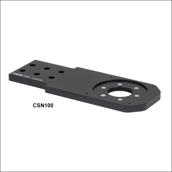
The CSN100 Single-Objective Nosepiece holds a single objective at the 7.74" throat depth of a DIY Cerna system. It is directly compatible with M32 x 0.75-threaded objectives. We also offer microscope thread adapters to convert M32 x 0.75 threads to other industry-standard objective threads.
The nosepiece has a thin 0.38" profile that conserves distance along the optical path, maximizing the space available for other microscope modules. The nosepiece has four 4-40 through taps for 60 mm cage system compatibility. It can be attached to a motorized focusing module (available below) by connecting to an angle bracket (available below) via six M4 counterbores. Recessed magnets on top of the nosepiece mate to the bellows included with Cerna microscope bodies with epi-illumination arms, creating a light-tight optical path between the nosepiece and the epi-illumination arm.
For machining an arm utilizing non-standard nosepiece threading, consider the CSA1500 blank arm, which can also be attached to our motorized focusing module.

 Zoom
Zoom| Item # | CSN110 |
|---|---|
| Number of Objectives | One |
| Objective Threads | M32 x 0.75 |
| 60 mm Cage System Compatible | Yes |
| 30 mm Cage System Compatible | Yes |
| Required Mounting Arm | CSA1400 Mounting Arm |
- Hold One Objective in a DIY Cerna System
- CSN110: M32 x 0.75 Internal Threads and 30 mm and 60 mm Cage System Compatibility
- Attach to Motorized Focusing Module for 1" of Fine Z Travel
The CSN110 Nosepiece Mounting Arm Adapter holds a single objective at the 7.74" throat depth of a DIY Cerna system when connected to the CSA1400 Mounting Arm (sold separately). The adapter connects to the mounting arm using a male D1T dovetail, and recessed magnets on the mounting arm mate to the bellows included with Cerna microscope bodies with epi-illumination arms. This creates a light-tight optical path between the nosepiece and the epi-illumination arm. To connect with our motorized focusing module, the CSA1400 arm mounts to an angle bracket (sold separately below).
The CSN110 adapter is directly compatible with M32 x 0.75-threaded objectives. We also offer microscope thread adapters to convert the M32 x 0.75 threads to other industry-standard objective threads.
This adapter has four through holes with side-located locking setscrews (5/64" [2 mm] hex), allowing for the attachment of Ø6 mm cage rods for 60 mm cage systems. Additionally, the side opposite the dovetail has 4-40 tapped holes on 30 mm centers for 30 mm cage systems.

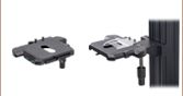
 Zoom
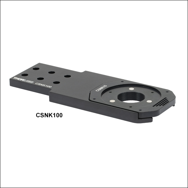
Zoom| Item # | CSNK100 |
|---|---|
| Number of Objectives | One |
| Objective Threads | M32 x 0.75 |
| 60 mm Cage System Compatible | Yes |
| Magnetic Removable Objective Mount |
CSNK10 (One Included) |

Click for Details
A CSNK100 nosepiece with the included CSNK10 magnetic removable objective mount. Kinematic positioning allows the CSNK10 objective mount to be removed and replaced with high repeatability.
- Hold One Objective in a DIY Cerna System
- CSNK100: M32 x 0.75 Internal Threads, 60 mm Cage System Compatibility, and Magnetic Removable Objective Mount
- Additional CSNK10 Magnetic Removable Objective Mounts Available Separately
- Attach to Motorized Focusing Module for 1" of Fine Z Travel
The CSNK100 Kinematic Nosepiece holds a single objective at the 7.74" throat depth of a DIY Cerna system. It includes a mounting arm and a CSNK10 Magnetic Removable Objective Mount, as seen in the image to the right, and allows the user to quickly switch objectives without disrupting the setup. A ball and V-group design provides kinematic positioning, allowing the objective mount to be smoothly slid out and replaced with a typical repeatability of <±10 µm in the X and Y directions. This nosepiece has a 0.50" profile and is directly compatible with M32 x 0.75-threaded objectives.
The nosepiece mounting arm can be attached to our motorized focusing module by connecting to an appropriate angle bracket via six M4 counterbores (focusing module and angle brackets available below). It also has four 4-40 through taps for 60 mm cage system compatibility.
The CSNK10 Magnetic Removable Objective Mount is directly compatible with M32 x 0.75-threaded objectives. The four 4-40 through taps allow the user to build a removable section of a 60 mm cage system on the mount. Recessed magnets on top of the nosepiece mate to the bellows included with Cerna microscope bodies with epi-illumination arms, creating a light-tight optical path between the nosepiece and the epi-illumination arm. We also offer microscope thread adapters to convert M32 x 0.75 threads to other industry-standard objective threads.
For machining an arm utilizing non-standard nosepiece threading, consider the CSA1500 blank arm, which can also be attached to a motorized focusing module.

 Zoom
Zoom| Item # | CSN1201 |
|---|---|
| Number of Objectives | One |
| Objective Threads | M32 x 0.75 |
| Slot for DIC Objective Prisms |
Yes |
| Required Mounting Arm | CSA1200 Mounting Arm |
- Hold One Objective in a DIY Cerna System
- CSN1201: M32 x 0.75 Internal Threads and Slot for Differential Interference Contrast (DIC) Objective Prism
- Attach to Motorized Focusing Module for 1" of Fine Z Travel
The CSN1201 Single-Objective Nosepiece holds a single objective at the 7.74" throat depth of a DIY Cerna system. It is directly compatible with M32 x 0.75-threaded objectives. We also offer microscope thread adapters to convert M32 x 0.75 threads to other industry-standard objective threads.
The nosepiece is 2.17" long with a slot that accepts a DIC objective prism. It requires the CSA1200 Mounting Arm (sold separately) to connect to an angle bracket and mount to a motorized focusing module. The CSN1201 objective holder slides into the CSA1200 arm and can be secured with a side-located locking screw with a 2 mm hex. This allows the user to switch and secure objectives into position without disrupting the rest of the setup. Recessed magnets on the CSA1200 arm mate to the bellows included with Cerna microscope bodies with epi-illumination arms, creating a light-tight optical path between the nosepiece and the epi-illumination arm.
For machining an arm utilizing non-standard nosepiece threading, consider the CSA1500 blank arm, which can also be attached to a motorized focusing module.

 Zoom
Zoom| Item # | CSN200 | CSN210 |
|---|---|---|
| Number of Objectives | Two | |
| Objective Threads | M32 x 0.75a | |
| Objective Changing Mechanism | Manual | Motorized |
| Repeatabilityb | ±10 µm | ±5 µm |
| Position 1 to 2c | -200 µm to 0 | ±100 µm |
| Required Mounting Arm | CSA1400 Mounting Arm | |
- Hold Two Objectives in a DIY Cerna System
- CSN200: Manual, M32 x 0.75 Internal Threads
- CSN210: Motorized, M32 x 0.75 Internal Threads
- Attach to Motorized Focusing Module for 1" of Fine Z Travel
These nosepieces hold two objectives in DIY Cerna systems. They are ideal for constructing systems that use a low-magnification objective to find a region of interest and a high-magnification objective to image.
Each nosepiece includes a D1T dovetail to attach to the CSA1400 Mounting Arm (sold separately). Using the arm, the nosepiece can connect to an angle bracket and be mounted to a motorized focusing module. Recessed magnets on the CSA1400 arm mate to the bellows included with Cerna microscope bodies with epi-illumination arms to create a light-tight optical path between the nosepiece and the epi-illumination arm. To switch and secure objectives into position, the CSN200 nosepiece uses a manual slide with detents, whereas the CSN210 nosepiece uses a precision servo motor. Please see the table to the right for more details on the performance specifications.
The motorized objective changer is controlled remotely on a PC (not included) using the included 6 ft USB cable and software; a link to download the software is also provided below. The motorized nosepiece features collision detection and will stop immediately when interference is detected. It must be rehomed before it can resume normal operation after a collision. The positions should only be changed using the motor. If it is moved manually, the nosepiece must be rehomed before it can move to either position again.


The CSN210 nosepiece can be mounted in two orientations, parallel to the epi-illumination path (shown left with the CSN200), or perpendicular to the epi-illumination path (shown right with the CSN210). Each nosepiece attaches to the motorized focusing module with an angle bracket via the CSA1400 mounting arm, which is sold separately. Note that to mount the CSN210 parallel to the epi-illumination path, the PLSZ2 angle bracket needs to be used with the PLSZ module. Objectives are not included with the nosepieces. Note also that the bellows shown here is longer than the standard bellows included with a microscope body.
Motorized Nosepiece
Software
Version 4.0 (August 16, 2018)
This software package contains the installation files for the GUI interface, driver, SDK, and support documentation. The software is compatible with Windows® 7 or 10 (64-bit) systems.

 Zoom
Zoom| Item # | CSN1202 |
|---|---|
| Number of Objectives | Two |
| Objective Threads | M25 x 0.75a |
| Objective Changing Mechanism | Manual |
| Per-Objective Parfocal Adjusters | Yes |
| Slots for DIC Objective Prisms |
Yes |
| Required Mounting Arm | CSA1200 Mounting Arm |
- Hold Two Objectives in a DIY Cerna System
- CSN1202: Manual, M25 x 0.75 Internal Threads and Slots for Differential Interference Contrast (DIC) Objective Prisms
- Attach to Motorized Focusing Module for 1" of Fine Z Travel
This nosepiece holds two objectives in DIY Cerna systems. It is ideal for constructing systems that use a low-magnification objective to find a region of interest and a high-magnification objective to image. This objective holder offers parfocal adjustment for the objectives and each position has a slot that accepts a DIC objective prism.
The nosepiece requires the CSA1200 Mounting Arm (sold separately) to connect to an angle bracket and mount to a motorized focusing module. The CSN1202 objective holder slides into the CSA1200 arm and can be secured with a side-located locking screw with a 2 mm hex. Recessed magnets on the CSA1200 arm mate to the bellows included with Cerna microscope bodies with epi-illumination arms to create a light-tight optical path between the nosepiece and the epi-illumination arm.
The CSN1202 nosepiece switches between objectives using a manual mechanism that retracts the objective that is not in use to avoid collisions with your sample, as demonstrated in the video below. Additionally, each objective position has an independent adjuster knob that can be used to fine tune the objectives' parfocality. To help ensure the objectives' relative centration, the front objective position has three 2 mm hex adjustment screws, arranged 120° apart, which adjust that objective's transverse position.

Click to Enlarge
The CSN1202 nosepiece retracts the objective that is not in use. It attaches to the motorized focusing module via the CSA1200 mounting arm, which is sold separately. For clarity, the nosepiece is shown here with objectives and objective prisms installed; these items are not included with the nosepiece.

 Zoom
Zoom
Click to Enlarge
Exploded View

Click to Enlarge
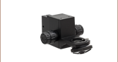
Assembled View
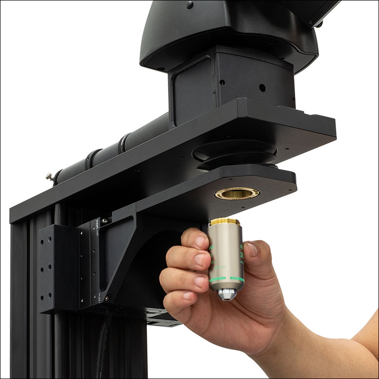
The scanner is installed by threading a brass adapter into the microscope's objective holder with the included spanner wrench and tightening a flexure clamp around the adapter with the included 5/64" (2 mm) hex key. The objective is attached to the scanner using a separate brass adapter and flexure clamp.
- Enables Objective Positioning and Z-Stack Acquisition with Resolution Down
to 1 nm - Travel Range: 600 µm ± 10% in Open Loop; 450 µm in Closed Loop
- Support for Heavy Objectives up to 500 g
- Maximum Clear Aperture of Ø29.0 mm Supports Large-Field-of-View Objectives
- Requires Microscope and Objective Adapters (Sold Separately)
The PFM450E Piezo Objective Positioner is designed for fine focus adjustment and high-speed Z-stack acquisition. Built-in capacitive feedback sensors allow the scanner to provide 1 nm resolution in open-loop operation and 3 nm resolution in closed-loop operation, enabling active compensation for short- and long-term drifts.
In order to permit easy switching between objectives, the piezo stage is attached to the microscope and objective by independent adapters. This design choice allows the objective to be removed without disconnecting the rest of the assembly. Adapters are available for M32 x 0.75, M27 x 0.75, SM1 (1.035"-40), M26 x 0.706, M25 x 0.75, and RMS (0.800"-36) threads. At least one microscope adapter and one objective adapter are required to install the scanner.
Each scanner is shipped with a piezo controller that has been factory calibrated to the specific scanner. Objective positioning is supported through the included standalone Kinesis® and APT™ GUIs, our ThorImage®LS image acquisition software, an externally supplied control voltage, or the MZF001 Joystick Console (sold separately). The controller offers USB and RS-232 interfaces for computer control; a BNC input for sine, sawtooth, and square wave drive signals; a BNC output that gives either positioning feedback from the scanner's built-in capacitive sensors or a signal proportional to the piezo drive voltage; and a connector for the MZF001 joystick. In addition, a DB15 connector provides signals that can be used for synchronization with external equipment.
More details on this scanner are available at its full web presentation. Please note that if installing it on the CSN200 or CSN210 Sliding Dual-Objective Nosepieces, the piezo stage and two adapters will add 11.5 mm of distance to the optical path, which will affect the objectives' parfocality. Also note that this scanner is not compatible with the CSN1202 Dual-Objective Nosepiece, as the flange on the PFMA05 Microscope Adapter will mechanically clash with the neighboring objective.

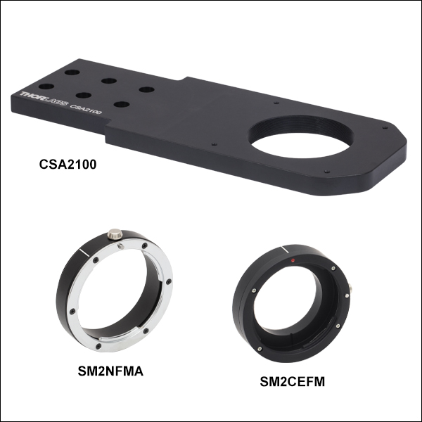 Zoom
Zoom
Click to Enlarge
In this photo, our SM2NFMA F-Mount Adapter is holding a macro lens for functional imaging.
Click to Enlarge
When the CSA2100 is attached to the microscope body, the internal SM2 threads and taps for 60 mm cage systems will be centered around the microscope's 7.74" throat depth.
- Nosepiece and Adapters Together Mount F-Mount or EF-Mount Macro Lenses
- The SM2NFMA Adapter Mounts F-Mount-Compatible Macro Lenses
- The SM2CEFM Adapter Mounts EF-Mount-Compatible Macro Lenses
- CSA2100 Internal SM2 (2.035"-40) Threads and 4-40 Taps for 60 mm Cage System
- Attach to Motorized Focusing Module for 1" of Fine Z Travel
The CSA2100 Arm is designed to be mounted in a DIY Cerna system via the motorized focusing module and angle brackets sold below. When combined with the SM2NFMA F-Mount Adapter or the SM2CEFM EF-Mount Adapter, it allows for any camera lens with F-Mount or EF-Mount compatibility, respectively, to be mounted at the Cerna system's 7.74" throat depth.
This arm offers a slim 0.38" profile, internal SM2 (2.035"-40) threads, and four 4-40 through taps for Thorlabs' 60 mm cage system. The SM2NFMA and SM2CEFM adapters have female F-Mounts and female EF-Mounts, respectively, that accept lenses and external SM2 threads that mate to the nosepiece.
The use of our standard SM2 threads also makes this arm compatible with any custom optical system mounted using our Ø2" lens tubes, as well as the CSA2001 D3N Dovetail Adapter.
To connect two M52 x 0.75-threaded macro lenses in tandem, as shown in the image to the right, consider using the M52A1 coupler.

 Zoom
Zoom| Motorized Translation Stage Specificationsa | |
|---|---|
| Travel Range | 1" (25.4 mm) |
| Bidirectional Repeatability | 5 µm |
| Backlash | 10 µm |
| Minimum Achievable Incremental Movement |
424 nm |
| Minimum Achievable Repeatable Movement |
1.06 μm |
| Velocity (Max) | 7 mm/s |
| Acceleration (Max) | 11 mm/s2 |
| Cable Length | 6' (1.8 m) |
| Pin Diagram | Click to View |
| Load Capacity | |
| Stage Mounted to Vertical Railb |
Recommended: ≤5 lbs (2.3 kg) Maximum: 8 lbs (3.6 kg) |
| Stage Mounted to Horizontal Rail |
Recommended: ≤20 lbs (9.1 kg) Maximum: 33 lbs (15 kg) |
| Stepper Motor Specifications | |
| Thread Screw Pitch | 0.3 mm |
| Step Angle | 1.8° |
| Limit Switches | Hall Effect Sensors |
| Phase Current | 0.49 A |
| Phase Resistance | 5.1 Ω |
| Insulation Resistance | 20 MΩ |
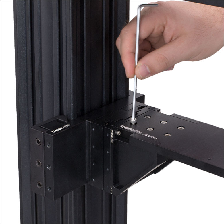
- Provides Motorized Focusing Adjustment over 1" Travel Range
- 95 mm Dovetail Clamp on Back Connects to Microscope Body
- Angle Brackets Available for Attaching Objective Nosepiece or Mounting Arm
- Each Includes Four 4-40 Cap Screws for Connecting to PLSZ Motorized Focusing Module
- Each Includes Six M4 Cap Screws for Attaching Condenser Arm
- Aligns Optical Port of Arm at 7.74" Throat Depth of DIY Cerna System
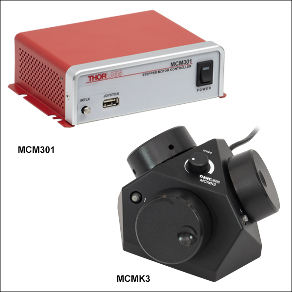
- Operated by MCM301 3-Axis Controller (Sold Separately Below)
Our Motorized Focusing Module provides 1" of fine, variable-speed travel along the Z axis for optics in a DIY Cerna system. Each PLSZ module consists of a 95 mm dovetail clamp that connects to the microscope body and a motorized translation stage that connects to our angle brackets (sold separately) for mounting an objective nosepiece or condenser arm. A permanently attached 6' (1.8 m) cable connects the module to our MCM301 3-Axis Controller (sold separately below).
The PLSZ1 and PLSZ2 angle brackets are designed for edge-mounted and middle-mounted arms, respectively. Each bracket has four holes for 4-40 screws, allowing it to connect with the PLSZ module, and six M4 tapped holes that are spaced to mate with the M4 counterbores on our objective nosepieces. Included with each bracket are four 4-40 cap screws, six M4 x 0.7 cap screws, and a 3/32" (2.5 mm) hex key. For alignment, the PLSZ1 and PLSZ2 also include four or two Ø0.12" (Ø3.0 mm) dowel pins, respectively. When an arm is connected to the PLSZ with one of these angle brackets, its optical port will be aligned at the 7.74" throat depth of the DIY Cerna system.
The PLSZ1 and PLSZ2 angle brackets can be mounted to the PLSZ module in either of two orientations, and the PLSZ module can be mounted on the microscope body in either of two orientations. This provides numerous mounting options for the objective nosepiece that allows the user to make the most efficient use of space. As shown in the diagram below, a nosepiece that is mounted to the PLSZ1 angle bracket will have one surface in the same plane as the edge of the module. In comparison, a nosepiece that is mounted to the PLSZ2 angle bracket will have one surface in the plane that bisects the module, which is 1.5" away from the module's edge. When selecting an angle bracket and positioning the stage on the microscope body, it is important to consider the clearance needed for the stage to be able to travel its full range of motion and the desired spacing between adjacent components in the optical path. For cases where the final position of the arm needs to be as close as possible to either end of the rail or another adjacent component in the optical path, we recommend using the PLSZ1 bracket to mount the arm at the top or bottom edge of the stage.
If using the PLSZ motorized focusing module for the CSN200 or CSN210 Sliding Dual-Objective Nosepieces (described above), it is strongly recommended to use the PLSZ2 bracket for mounting. The CSA1400 Mounting Arm, which is used to attach this nosepiece to the angle bracket, will mechanically clash with the PLSZ1 bracket in most mounting configurations.
Our PLST(/M) top plate can also be mounted to the PLSZ module, expanding the versatility of the stage well beyond microscopy and providing options for custom mounting needs.
Click to Enlarge
Six M4 cap screws are included with each angle bracket to connect with condenser arms.
Click for Details
The PLSZ module has two possible orientations, creating space along the optical path for mounted optomechanical assemblies.
When using the PLSZ1 angle bracket with the PLSZ module, the surface of the nosepiece or arm will be flush with the bottom (or top) of the module.
When using the PLSZ2 angle bracket with the PLSZ module, the surface of the nosepiece or arm will be at the middle of the module.

 Zoom
Zoom
| Compatible Stages | |
|---|---|
| Motorized Focusing Module | |
| Translation Stages for Rigid Stands | |
| Motorized Vertical Rigid Stands |
| Controller Specifications |
|---|
| Compatible Motor Specifications |
|---|
Software
Version 1.0 (November 10, 2023)
The software package contains the installation files
for the GUI interface, driver, and SDK. The software is compatible with Windows® 7 (64 bit) and later systems.
- Designed for Cerna Components with 1" Motorized Travel
- Provides Control for up to Three Channels
- Separately Available Three-Knob Joystick Allows Hand Operation
- Each Axis can be Individually Disabled to Prevent
Unintended Movements or to Retain a Position - Dial on Top of Three-Knob Joystick Adjusts Translation Speed
The MCM301 3-Axis Controller is designed for use with Thorlabs' Motorized Focusing Module, Motorized Rigid Stand Translation Stages, and Motorized Vertical Rigid Stands. The MCMK3 3-Knob Joystick, available separately, can be connected to provide hand-operation. The controller can also be operated remotely using standalone software.
Each side face of the optional MCMK3 joystick includes a rotating knob and a push-button switch that are dedicated to a single axis. The push-button switch on the joystick enables and disables the axis and is lit in green when the axis is enabled. Disabling the axis lets the user preserve a position or prevent accidental movements. A dial on the top face adjusts the velocity per rotation of the knobs. For more information on the MCMK3 joystick and how to utilize the USB HID protocol, please see the full web presentation.
Since each MCM301 controller has three channels, you only need to purchase enough channels for each of the modules you intend to drive. For example, a Cerna microscope equipped with a PLSZ Motorized Focusing Module (which has one axis) and a PLSXY Translation Stage (two axes) would only require one MCM301 controller.For more information, as well as compatible software and a LabVIEW™/C++/Python SDK, please see the full web presentation for the MCM301 controller.
| Item # | SM1N5 |
|---|---|
| Photo (Click for Details) |
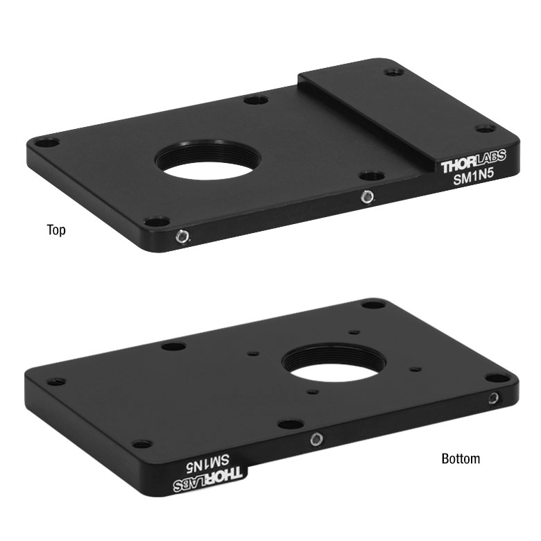 |
| Microscope Connection | M5 x 0.8 Mounting Hole (2 Places) |
| SM Threading | Internal SM1 (1.035"-40) |
| Cage Compatibility |
30 mm Cage System (4-40 Tap, 4 Places) 60 mm Cage Systema (Ø6 mm Bore, 4 Places) |
| Microscope Compatibility | Nikon Eclipse Ti2 |
| Adapter Profile (Click for Drawing) |
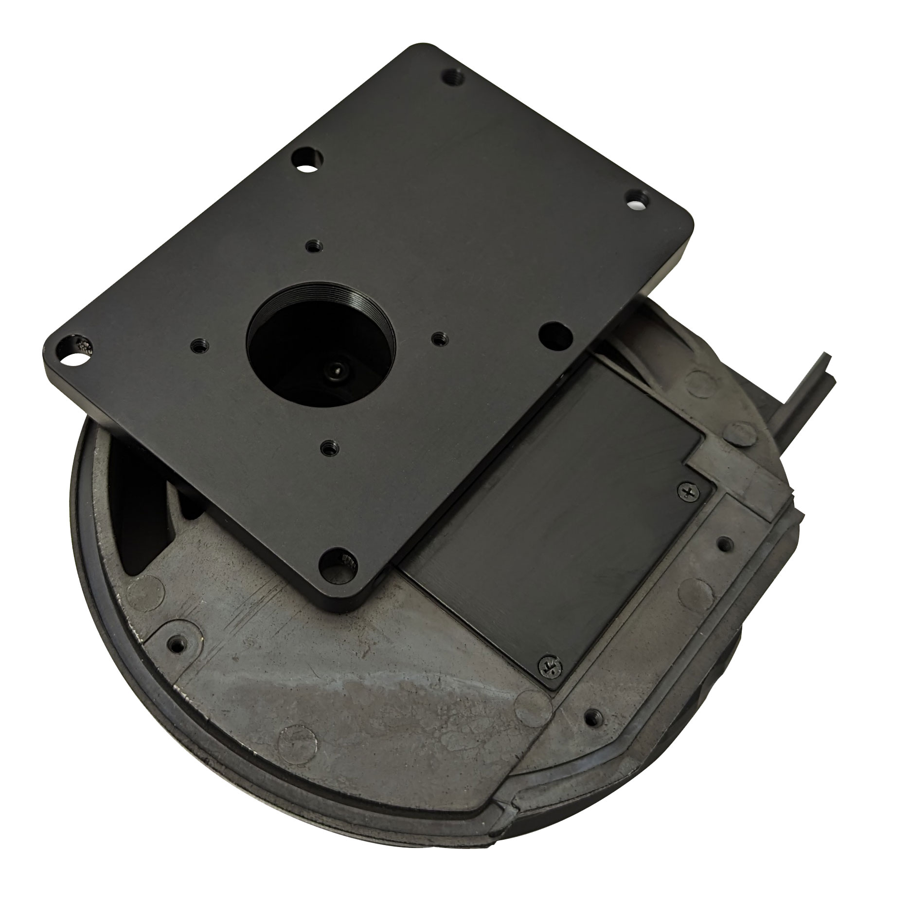
Click to Enlarge
The SM1N5 Adapter mounted on a Nikon nosepiece.
- Supports Integration of Nikon Eclipse Ti2 Nosepieces into Cerna Microscope Systems with 60 mm Cage Compatibility
- Allows Externally SM1-Threaded Components to be Threaded onto Nikon Eclipse Ti2 Microscope Nosepieces
- Compatible with 30 mm and 60 mm Cage Construction Systems
The SM1N5 Nosepiece Adapter has a set of four through holes with side-located locking setscrews (5/64" [2 mm] hex) which provide 60 mm cage system compatibility. This allows the use of a set of cage rods to mount the SM1N5 adapter and an attached Nikon Ti2 nosepiece to a Cerna nosepiece or mounting arm with 60 mm cage compatibility. This adapter is also designed to allow Thorlabs' externally SM1-threaded components to be threaded onto Nikon Ti2 nosepieces via an internally SM1-threaded central bore. A set of four 4-40 tapped holes on 30 mm centers allow for integration with 30 mm cage systems.
The input port of the Nikon nosepiece can be accessed by unscrewing the captive M5 screws on the nosepiece and removing it from the Nikon Eclipse Ti2. To attach the SM1N5 adapter, align the captive M5 screws with the threaded M5 x 0.8 mounting holes of the adapter; the raised portion of the adapter should face towards the nosepiece so the adapter lays flat, allowing access to the 4-40 tapped holes as shown in the image to the right. Once aligned, the captive M5 screws can be screwed into the adapter mounting holes. The Nikon nosepiece and attached SM1N5 adapter can then be mounted using 60 mm cage rods to a compatible Cerna nosepiece or mounting arm.
Note: Thorlabs does not guarantee compatibility with other industry-standard microscopes not explicitly mentioned on this webpage.