 Products Home / Fiber Components / Fused Fiber Optic WDMs / 2-Wavelength, Polarization-Maintaining WDMs
2-Wavelength, Polarization-Maintaining WDMs
- Combine Two Wavelengths in PM PANDA Fiber
- Unterminated, FC/PC, or FC/APC Outputs
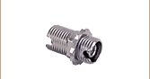
- Connector Key Aligned to Slow Axis
Combine Two Wavelengths into a Single Fiber Output
WP9850B
980 nm / 1550 nm WDM with Unterminated Outputs
WP9864A
980 nm / 1064 nm WDM with FC/APC Connectors
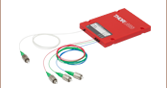
Split Two Wavelengths from a Single Fiber Input


Please Wait
Click for Details
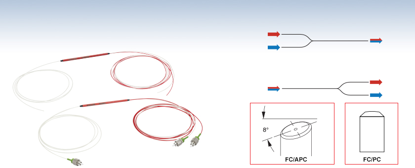
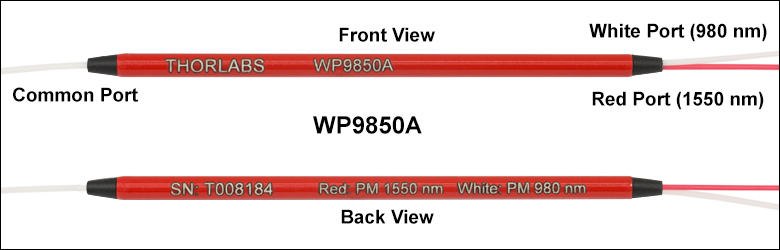
Figure 1.1 The housings of our WDMs are engraved with the Item # and port wavelengths. The common port is located on the single fiber side and has a white jacket.
 ) next to the Item # and entering your device's serial number under "Download Serial Item Data." If your device was provided with a paper copy of the test results and you prefer an electronic version, please contact Tech Support.
PANDA PM Fiber
Cross Section
Figure 1.2 The connector key is aligned to the slow axis of the fiber.
Features
- Wavelength Division Multiplexers (WDMs) Using PM PANDA Fiber
- Combine or Split Two Wavelengths
- 980 nm / 1064 nm
- 980 nm / 1550 nm
- 1310 nm / 1550 nm
- 0.8 m Long Fiber Leads with a Tolerance of +0.075 m / -0.0 m
- Slow Axis Aligned to Connector Key
- Individual Test Report Available for Each Coupler (See the
PER Measurement Tab; Click Here for a Sample Test Report)
Thorlabs' Fused Polarization Maintaining (PM) Wavelength Division Multiplexers (WDMs) combine two wavelengths of light in PM fiber while maintaining the polarization of the incident light. These WDMs are reversible; they can also be used to split two discrete wavelengths entering the common port into two separate output ports. They are not designed to split the output from a broadband source. They can be readily customized for a wide variety of applications, enabling rapid design cycles and new project builds.
PM WDMs are available with three wavelength combinations, 980 nm / 1064 nm, 980 nm / 1550 nm, or 1310 nm / 1550 nm. They are also available with FC/PC or FC/APC connectors, or with unterminated fiber ends. These WDMs are manufactured using PANDA-style PM fiber which allows them to maintain a high polarization extinction ratio (PER) when light is launched along the slow axis of the fiber. As seen in Figure 1.2, stress rods run parallel to the fiber's core creating birefringence which allows for polarization-maintaining operation.
Thorlabs' PM WDMs provide an PER of ≥20 dB including connectors and a wide -40 °C to 85 °C operating range. These WDMs undergo extensive testing and verification of the PER; details of our testing procedures are provided in the PER Measurement tab. A test report containing test results is available for each WDM; a sample test report for the 980 nm / 1550 nm PM WDMs can be viewed here. In addition, a specification sheet with a plot of the insertion loss is available for each coupler; click the red Docs icon
() below. All specifications are based on a slow axis launch.
Custom and OEM WDMs
Our WDMs are produced on-site in our North American manufacturing facilities and our design team is able to deliver custom solutions in as little as three weeks. Custom WDM configurations with other connectors, fiber types, port configurations, housing options, or select wavelength combinations are available, and each custom WDM includes an individualized test report. Please contact Tech Sales for inquiries or to discuss your application.
| Other Wavelength Division Multiplexers (WDMs) | |||||
|---|---|---|---|---|---|
| 2-Wavelength WDMs | 3-Wavelength WDMs | Polarization-Maintaining WDMs | Fused Fiber Couplers |
||
| Visible/NIR (λ ≤ 785 nm) | Infrared (λ ≥ 980 nm) | Visible/NIR | Visible | Infrared | |
Video 2.1 1x2 Wavelength Division Multiplexers
Wavelength Division Multiplexer Design
Thorlabs' Wavelength Division Multiplexers (WDMs) are designed to combine or split light at two different wavelengths. Thorlabs offers a variety of multiplexers with wavelength combinations spanning the visible, near-IR, and IR regions of the spectrum. Our visible wavelength division multiplexers are also known as "wavelength combiners" as they are commonly used in microscopy applications to generate multi-color composite images.
Video 2.1 illustrates the basic operating principles of a 1x2 WDM. When combining light, the wavelength-specific ports will transmit light within a specified bandwidth region and combine them into a multi-wavelength signal output at the common port, with minimal loss in signal.
Except where indicated, our WDMs are bidirectional; they can also split a two-wavelength signal that is inserted into the common port into the component wavelengths. For optimal combining/splitting performance, the input signal(s) should contain only the wavelengths specified for the WDM. An insertion loss graph can help determine the transmission and coupling performance within and outside the specified bandwidth. For our WDMs that have red, engraved housings, this data is included with the item-specific datasheet that ships with each coupler.
Click to Enlarge
Figure 2.2 The shaded regions in the plot indicate the bandwidth where each port meets the specified performance.
Insertion Loss and Isolation
WDM performance is typically quantified using insertion loss. As seen in Equation 1, insertion loss (measured in dB) is the ratio of the input power to the output power from each leg of the WDM. For optical systems, the definition of insertion loss is given as:
where Pin and Pout are the input and output powers (in mW).
Each port of the coupler is designed to have low insertion loss (i.e., high transmission) at the desired wavelength while suppressing the signal at the specified wavelength of the other port, which minimizes cross talk between the ports. Therefore, isolation is specified as the insertion loss of these undesired wavelengths. High dB values of isolation are ideal for signal separation applications using a WDM. For example, in Figure 2.2, the long wavelength port (shown using a red dashed line) has a low insertion loss around 640 nm (indicated by the red shaded region), but exhibits high isolation (>25 dB) in the region specified for the short wavelength port (indicated by the light blue shaded region).
Wavelength Division Multiplexer Manufacturing Process
This section details the steps used in manufacturing and verifying the performance of our wavelength division multiplexers.

Click to Enlarge
Figure 2.3 In the diagram, the fibers are color-coded; blue for the short wavelength port and red for the long wavelength port.
Step 1
At the first stage, two fibers are fused on a manufacturing station so that the two fiber cores are in close proximity. This allows light to propagate between the two fiber cores over the fused region in a process known as evanescent coupling. The fusing process is stopped once the desired insertion loss and isolation specifications are achieved.
The output from the short wavelength port is monitored during the fusing process using a broadband source on one side and an optical spectrum analyzer (OSA) on the other. The insertion loss as a function of wavelength is calculated from the spectrum obtained from the OSA.
Click to Enlarge
Figure 2.4 In the diagram, the fibers are color-coded; blue for the short wavelength port and red for the long wavelength port.
Step 2
To verify the WDM performance, the output is measured in the long wavelength port using a broadband source and OSA. By combining the plots obtained in steps 1 and 2, the insertion loss and isolation in each channel can be calculated.
| Table 98B Component List | ||
|---|---|---|
| Item #a | Description | Qty. |
| Light Source (Not Shown) | ||
| S5FC1005P | PM Benchtop SLD Source, 1550 nm | 1 |
| P1-1550PM-FC-1 | Patch Cable, FC/PC, 1550 nm, PM Panda Style, 1 m | 1 |
| Linear Polarizer Module | ||
| PAF-X-11-PC-Cb | FiberPort, FC/PC, 1050 nm - 1620 nm |
2 |
| CP08FP(/M) | Cage Plates for Mounting FiberPorts | 2 |
| LPNIR050-MP2 | Linear Polarizer | 1 |
| CRM1P(/M) | Cage Rotation Mount | 1 |
| SM1A6T | Adapter with External SM1 Threads and Internal SM05 Threads | 1 |
| ER2-P4 | 2" (50.8 mm) Long Cage Rods, 4 Pack | 1 |
| Analyzer Module | ||
| PAF-X-11-PC-Cb | FiberPort, FC/PC, 1050 nm - 1620 nm |
1 |
| CP08FP(/M) | Cage Plates for Mounting FiberPorts | 1 |
| LPNIR050-MP2 | Linear Polarizer | 1 |
| CRM1P(/M) | Cage Rotation Mount | 1 |
| SM1A6T | Adapter with External SM1 Threads and Internal SM05 Threads | 1 |
| CP33(/M) | SM1-Threaded (1.035"-40) Cage Plate |
1 |
| PM400K4 | Digital Power Meter, 700 - 1800 nm | 1 |
| ER2-P4 | 2" (50.8 mm) Long Cage Rods, 4 Pack | 1 |
Click to Enlarge
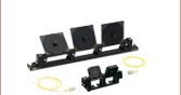
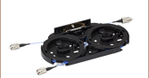
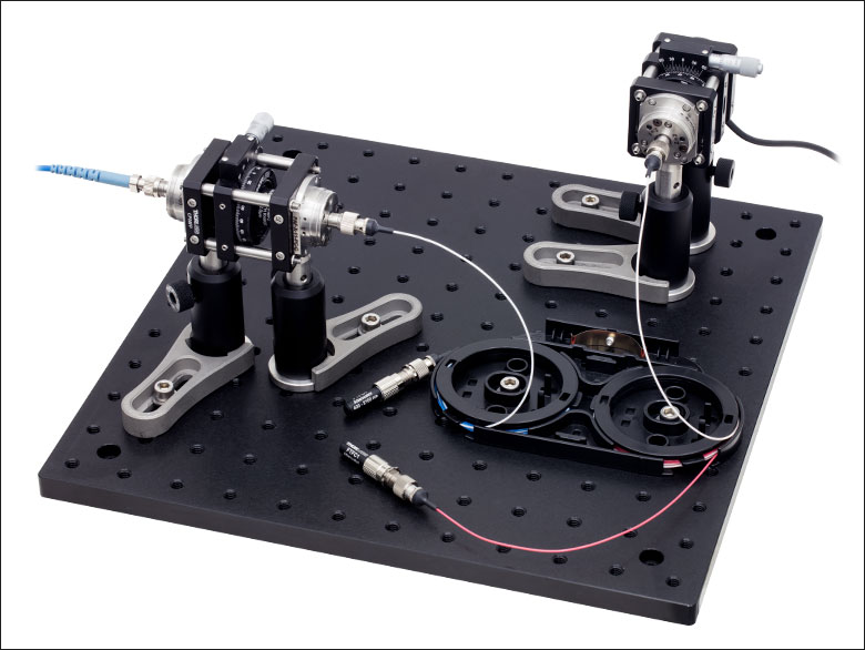
Figure 98A Setup to Measure the Extinction Ratio of a 1550 nm PM Coupler
Measurement of Polarization Extinction Ratio (PER)
The polarization extinction ratio (PER) is a measure of how well a polarization-maintaining (PM) fiber or device can prevent cross coupling between the different polarization axes of the fiber. External stress on a fiber from sources such as heating, bending, or pulling can cause the PER to change.
There are two accepted techniques for measuring PER in a fiber coupler. The most common method uses a low-coherence (unpolarized or circularly polarized) broadband light source and measures the extinction ratio with a linear polarizer and power meter. An alternative method uses a narrowband, high-coherence light source and measures the PER with a polarimeter.
Thorlabs uses the power meter method to characterize the extinction ratio performance of the PM fiber couplers sold on this page. An example setup is shown in Figure 98A with itemized component list in Table 98B. A broadband light source is input into a linear polarizer module, which allows the user to set the polarization of light entering the input leg of the fiber coupler. The output from one of the legs is sent to the analyzer module, which contains another polarizer and the power meter for measuring the output. Alternatively, the analyzer module can be replaced with an extinction ratio meter.
The PER is measured using the following test procedure:
- Prepare the fiber end faces of the PM coupler to connect to the measurement setup.
- For bare fiber ends, strip and cleave the fibers. Use a bare fiber terminator, such as the BFT1, to create a temporary fiber termination.
- For terminated fiber ends, clean and inspect the connector end faces.
- Attach a fiber optic light trap to any fiber leads not being measured.
- Adjust the polarizers in the linear polarizer and analyzer modules sequentially until a minimum power value is measured by the power meter. Record the measured value as Pmin.
- Rotate the analyzer rotation mount by 90°. Then record the measured value as Pmax.
After Pmin and Pmax are measured, the extinction ratio can be calculated:
Click to Enlarge
Figure 98D 7-hour temperature cycling test performed on a standard PN1550R5A1 PM fiber coupler shows that the PER measured for the white-white and white-red paths remains stable over a wide temperature range.
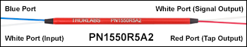
Figure 98C The White-White Path Follows the Input to Signal Output and the White-Red Path Follows the Input to Tap Output
Temperature Cycling Tests
Traditional PM couplers typically exhibit diminished polarization extinction ratio (PER) performance when used at sub-zero (°C) temperatures due to the contraction of the adhesives that are used to assemble the device. This effect disrupts the polarization state of light within the coupler and leads to a decrease in PER. Soft adhesives can be used to mitigate the impact of cold-temperature operation but can create reliability issues at higher temperatures. At high temperatures, adhesives can soften permanently, which changes the optical properties of the coupler.
Unlike traditional coupler manufacturing, Thorlabs uses a proprietary packaging process and design for our standard PM couplers as well as careful selection of adhesives to enable operation over a very wide temperature range (from -40 °C to 85 °C) without significant changes to PER and other optical specifications.
| Quick Links |
|---|
| Damage at the Air / Glass Interface |
| Intrinsic Damage Threshold |
| Preparation and Handling of Optical Fibers |
Laser-Induced Damage in Silica Optical Fibers
The following tutorial details damage mechanisms relevant to unterminated (bare) fiber, terminated optical fiber, and other fiber components from laser light sources. These mechanisms include damage that occurs at the air / glass interface (when free-space coupling or when using connectors) and in the optical fiber itself. A fiber component, such as a bare fiber, patch cable, or fused coupler, may have multiple potential avenues for damage (e.g., connectors, fiber end faces, and the device itself). The maximum power that a fiber can handle will always be limited by the lowest limit of any of these damage mechanisms.
While the damage threshold can be estimated using scaling relations and general rules, absolute damage thresholds in optical fibers are very application dependent and user specific. Users can use this guide to estimate a safe power level that minimizes the risk of damage. Following all appropriate preparation and handling guidelines, users should be able to operate a fiber component up to the specified maximum power level; if no maximum is specified for a component, users should abide by the "practical safe level" described below for safe operation of the component. Factors that can reduce power handling and cause damage to a fiber component include, but are not limited to, misalignment during fiber coupling, contamination of the fiber end face, or imperfections in the fiber itself. For further discussion about an optical fiber’s power handling abilities for a specific application, please contact Thorlabs’ Tech Support.
Damage at the Air / Glass Interface
There are several potential damage mechanisms that can occur at the air / glass interface. Light is incident on this interface when free-space coupling or when two fibers are mated using optical connectors. High-intensity light can damage the end face leading to reduced power handling and permanent damage to the fiber. For fibers terminated with optical connectors where the connectors are fixed to the fiber ends using epoxy, the heat generated by high-intensity light can burn the epoxy and leave residues on the fiber facet directly in the beam path.
| Table 36C Estimated Optical Power Densities on Air / Glass Interfacea | ||
|---|---|---|
| Type | Theoretical Damage Thresholdb | Practical Safe Levelc |
| CW (Average Power) |
~1 MW/cm2 | ~250 kW/cm2 |
| 10 ns Pulsed (Peak Power) |
~5 GW/cm2 | ~1 GW/cm2 |
Damage Mechanisms on the Bare Fiber End Face
Damage mechanisms on a fiber end face can be modeled similarly to bulk optics, and industry-standard damage thresholds for UV Fused Silica substrates can be applied to silica-based fiber. However, unlike bulk optics, the relevant surface areas and beam diameters involved at the air / glass interface of an optical fiber are very small, particularly for coupling into single mode (SM) fiber. therefore, for a given power density, the power incident on the fiber needs to be lower for a smaller beam diameter.
Table 36C lists two thresholds for optical power densities: a theoretical damage threshold and a "practical safe level". In general, the theoretical damage threshold represents the estimated maximum power density that can be incident on the fiber end face without risking damage with very good fiber end face and coupling conditions. The "practical safe level" power density represents minimal risk of fiber damage. Operating a fiber or component beyond the practical safe level is possible, but users must follow the appropriate handling instructions and verify performance at low powers prior to use.
Calculating the Effective Area for Single Mode Fibers
The effective area for single mode (SM) fiber is defined by the mode field diameter (MFD), which is the cross-sectional area through which light propagates in the fiber; this area includes the fiber core and also a portion of the cladding. To achieve good efficiency when coupling into a single mode fiber, the diameter of the input beam must match the MFD of the fiber.
As an example, SM400 single mode fiber has a mode field diameter (MFD) of ~Ø3 µm operating at 400 nm, while the MFD for SMF-28 Ultra single mode fiber operating at 1550 nm is Ø10.5 µm. The effective area for these fibers can be calculated as follows:
SM400 Fiber: Area = Pi x (MFD/2)2 = Pi x (1.5 µm)2 = 7.07 µm2 = 7.07 x 10⁻⁸ cm2
SMF-28 Ultra Fiber: Area = Pi x (MFD/2)2 = Pi x (5.25 µm)2 = 86.6 µm2 = 8.66 x 10⁻⁷ cm2
To estimate the power level that a fiber facet can handle, the power density is multiplied by the effective area. Please note that this calculation assumes a uniform intensity profile, but most laser beams exhibit a Gaussian-like shape within single mode fiber, resulting in a higher power density at the center of the beam compared to the edges. Therefore, these calculations will slightly overestimate the power corresponding to the damage threshold or the practical safe level. Using the estimated power densities assuming a CW light source, we can determine the corresponding power levels as:
SM400 Fiber: 7.07 x 10⁻⁸ cm2 x 1 MW/cm2 = 7.1 x 10⁻⁸ MW = 71 mW (Theoretical Damage Threshold)
7.07 x 10⁻⁸ cm2 x 250 kW/cm2 = 1.8 x 10⁻⁵ kW = 18 mW (Practical Safe Level)
SMF-28 Ultra Fiber: 8.66 x 10⁻⁷ cm2 x 1 MW/cm2 = 8.7 x 10⁻⁷ MW = 870 mW (Theoretical Damage Threshold)
8.66 x 10⁻⁷ cm2 x 250 kW/cm2 = 2.1 x 10⁻⁴ kW = 210 mW (Practical Safe Level)
Effective Area of Multimode Fibers
The effective area of a multimode (MM) fiber is defined by the core diameter, which is typically far larger than the MFD of an SM fiber. For optimal coupling, Thorlabs recommends focusing a beam to a spot roughly 70 - 80% of the core diameter. The larger effective area of MM fibers lowers the power density on the fiber end face, allowing higher optical powers (typically on the order of kilowatts) to be coupled into multimode fiber without damage.
Damage Mechanisms Related to Ferrule / Connector Termination
 Click to Enlarge
Figure 36D Plot showing approximate input power that can be incident on a single mode silica optical fiber with a termination. Each line shows the estimated power level due to a specific damage mechanism. The maximum power handling is limited by the lowest power level from all relevant damage mechanisms (indicated by a solid line).
Fibers terminated with optical connectors have additional power handling considerations. Fiber is typically terminated using epoxy to bond the fiber to a ceramic or steel ferrule. When light is coupled into the fiber through a connector, light that does not enter the core and propagate down the fiber is scattered into the outer layers of the fiber, into the ferrule, and the epoxy used to hold the fiber in the ferrule. If the light is intense enough, it can burn the epoxy, causing it to vaporize and deposit a residue on the face of the connector. This results in localized absorption sites on the fiber end face that reduce coupling efficiency and increase scattering, causing further damage.
For several reasons, epoxy-related damage is dependent on the wavelength. In general, light scatters more strongly at short wavelengths than at longer wavelengths. Misalignment when coupling is also more likely due to the small MFD of short-wavelength SM fiber that also produces more scattered light.
To minimize the risk of burning the epoxy, fiber connectors can be constructed to have an epoxy-free air gap between the optical fiber and ferrule near the fiber end face. Our high-power multimode fiber patch cables use connectors with this design feature.
Determining Power Handling with Multiple Damage Mechanisms
When fiber cables or components have multiple avenues for damage (e.g., fiber patch cables), the maximum power handling is always limited by the lowest damage threshold that is relevant to the fiber component. In general, this represents the highest input power that can be incident on the patch cable end face and not the coupled output power.
As an illustrative example, Figure 36D shows an estimate of the power handling limitations of a single mode fiber patch cable due to damage to the fiber end face and damage via an optical connector. The total input power handling of a terminated fiber at a given wavelength is limited by the lower of the two limitations at any given wavelength (indicated by the solid lines). A single mode fiber operating at around 488 nm is primarily limited by damage to the fiber end face (blue solid line), but fibers operating at 1550 nm are limited by damage to the optical connector (red solid line).
In the case of a multimode fiber, the effective mode area is defined by the core diameter, which is larger than the effective mode area for SM fiber. This results in a lower power density on the fiber end face and allows higher optical powers (on the order of kilowatts) to be coupled into the fiber without damage (not shown in graph). However, the damage limit of the ferrule / connector termination remains unchanged and as a result, the maximum power handling for a multimode fiber is limited by the ferrule and connector termination.
Please note that these are rough estimates of power levels where damage is very unlikely with proper handling and alignment procedures. It is worth noting that optical fibers are frequently used at power levels above those described here. However, these applications typically require expert users and testing at lower powers first to minimize risk of damage. Even still, optical fiber components should be considered a consumable lab supply if used at high power levels.
Intrinsic Damage Threshold
In addition to damage mechanisms at the air / glass interface, optical fibers also display power handling limitations due to damage mechanisms within the optical fiber itself. These limitations will affect all fiber components as they are intrinsic to the fiber itself. Two categories of damage within the fiber are damage from bend losses and damage from photodarkening.
Bend Losses
Bend losses occur when a fiber is bent to a point where light traveling in the core is incident on the core/cladding interface at an angle higher than the critical angle, making total internal reflection impossible. Under these circumstances, light escapes the fiber, often in a localized area. The light escaping the fiber typically has a high power density, which burns the fiber coating as well as any surrounding furcation tubing.
A special category of optical fiber, called double-clad fiber, can reduce the risk of bend-loss damage by allowing the fiber’s cladding (2nd layer) to also function as a waveguide in addition to the core. By making the critical angle of the cladding/coating interface higher than the critical angle of the core/clad interface, light that escapes the core is loosely confined within the cladding. It will then leak out over a distance of centimeters or meters instead of at one localized spot within the fiber, minimizing the risk of damage. Thorlabs manufactures and sells 0.22 NA double-clad multimode fiber, which boasts very high, megawatt range power handling.
Photodarkening
A second damage mechanism, called photodarkening or solarization, can occur in fibers used with ultraviolet or short-wavelength visible light, particularly those with germanium-doped cores. Fibers used at these wavelengths will experience increased attenuation over time. The mechanism that causes photodarkening is largely unknown, but several fiber designs have been developed to mitigate it. For example, fibers with a very low hydroxyl ion (OH) content have been found to resist photodarkening and using other dopants, such as fluorine, can also reduce photodarkening.
Even with the above strategies in place, all fibers eventually experience photodarkening when used with UV or short-wavelength light, and thus, fibers used at these wavelengths should be considered consumables.
Preparation and Handling of Optical Fibers
General Cleaning and Operation Guidelines
These general cleaning and operation guidelines are recommended for all fiber optic products. Users should still follow specific guidelines for an individual product as outlined in the support documentation or manual. Damage threshold calculations only apply when all appropriate cleaning and handling procedures are followed.
-
All light sources should be turned off prior to installing or integrating optical fibers (terminated or bare). This ensures that focused beams of light are not incident on fragile parts of the connector or fiber, which can possibly cause damage.
-
The power-handling capability of an optical fiber is directly linked to the quality of the fiber/connector end face. Always inspect the fiber end prior to connecting the fiber to an optical system. The fiber end face should be clean and clear of dirt and other contaminants that can cause scattering of coupled light. Bare fiber should be cleaved prior to use and users should inspect the fiber end to ensure a good quality cleave is achieved.
-
If an optical fiber is to be spliced into the optical system, users should first verify that the splice is of good quality at a low optical power prior to high-power use. Poor splice quality may increase light scattering at the splice interface, which can be a source of fiber damage.
-
Users should use low power when aligning the system and optimizing coupling; this minimizes exposure of other parts of the fiber (other than the core) to light. Damage from scattered light can occur if a high power beam is focused on the cladding, coating, or connector.
Tips for Using Fiber at Higher Optical Power
Optical fibers and fiber components should generally be operated within safe power level limits, but under ideal conditions (very good optical alignment and very clean optical end faces), the power handling of a fiber component may be increased. Users must verify the performance and stability of a fiber component within their system prior to increasing input or output power and follow all necessary safety and operation instructions. The tips below are useful suggestions when considering increasing optical power in an optical fiber or component.
-
Splicing a fiber component into a system using a fiber splicer can increase power handling as it minimizes possibility of air/fiber interface damage. Users should follow all appropriate guidelines to prepare and make a high-quality fiber splice. Poor splices can lead to scattering or regions of highly localized heat at the splice interface that can damage the fiber.
-
After connecting the fiber or component, the system should be tested and aligned using a light source at low power. The system power can be ramped up slowly to the desired output power while periodically verifying all components are properly aligned and that coupling efficiency is not changing with respect to optical launch power.
-
Bend losses that result from sharply bending a fiber can cause light to leak from the fiber in the stressed area. When operating at high power, the localized heating that can occur when a large amount of light escapes a small localized area (the stressed region) can damage the fiber. Avoid disturbing or accidently bending fibers during operation to minimize bend losses.
-
Users should always choose the appropriate optical fiber for a given application. For example, large-mode-area fibers are a good alternative to standard single mode fibers in high-power applications as they provide good beam quality with a larger MFD, decreasing the power density on the air/fiber interface.
-
Step-index silica single mode fibers are normally not used for ultraviolet light or high-peak-power pulsed applications due to the high spatial power densities associated with these applications.
| Posted Comments: | |
Daniel Higginbottom
(posted 2021-08-15 20:39:28.303) Hi,
I would like to request polarization maintaining 980/1330 wavelength division multiplexers. Is it possible to commission a custom part? YLohia
(posted 2021-08-27 03:04:47.0) Hello, custom WDMs can be requested by emailing techsales@thorlabs.com. We will discuss the possibility of offering this directly. user
(posted 2020-05-18 13:06:08.42) Is it possible to supply such a WDM for custom wavelengths? In particular, 760 nm and 935 nm are of interest. nbayconich
(posted 2020-05-19 04:26:50.0) Thank you for contacting Thorlabs. We can provide custom WDM's, I will reach out to you directly with more information. user
(posted 2015-11-30 10:18:33.653) Hi, how much insertion loss does WD202EPM have if I launch light in the fast axis, for both pump and signal? And how is the extinction ratio defined? Thank you. besembeson
(posted 2015-12-02 02:40:25.0) Response from Bweh at Thorlabs USA: You should expect similar performance with the fast axis. The extinction ratio will similarly be defined as 10 x log (power in slow axis/power in fast axis). |
| Item # | Info | Operating Wavelengths |
Bandwidth | Insertion Lossa |
Isolationa | Extinction Ratioa |
Directivitya | Max Powerb | Fiber Typec | Termination |
|---|---|---|---|---|---|---|---|---|---|---|
| WP9864B | 980 nm / 1064 nm | ±5 nm | ≤0.6 dB (Click for Plot) |
≥17 dB | ≥20 dB |
≥60 dB | 1 W (Bare Fiber) 5 W (Spliced) |
PM 98-U25D |
No Connectors, Scissor Cut |
|
| WP9864F | 1 W (Connectors or Bare) 5 W (Spliced) |
FC/PCd | ||||||||
| WP9864A | FC/APCd |
| Item # | Info | Operating Wavelengths |
Bandwidth | Insertion Lossa |
Isolationa | Extinction Ratioa |
Directivitya | Max Powerb | Fiber Typec | Termination |
|---|---|---|---|---|---|---|---|---|---|---|
| WP9850B | 980 nm / 1550 nm | ±10 nm / ±15 nm | ≤0.6 dB (Click for Plot) |
≥16 dB | ≥20 dB |
≥60 dB | 1 W (Bare Fiber) 5 W (Spliced) |
PM 98-U25D |
No Connectors, Scissor Cut |
|
| WP9850F | 1 W (Connectors or Bare) 5 W (Spliced) |
FC/PCd | ||||||||
| WP9850A | FC/APCd |
| Item # | Info | Operating Wavelengths |
Bandwidth | Insertion Lossa |
Isolationa,b | Extinction Ratioc |
Directivitya | Max Powerd | Fiber Typee | Termination |
|---|---|---|---|---|---|---|---|---|---|---|
| WP1350B | 1310 nm / 1550 nm | ±5 nm / ±5 nm | ≤0.6 dB (Click for Plot) |
≥17.0 dB | ≥20.0 dB |
≥60 dB | 1 W (Bare Fiber) 5 W (Spliced) |
PM 13-U25D |
No Connectors, Scissor Cut |
|
| WP1350F | 1 W (Connectors or Bare) 5 W (Spliced) |
FC/PCf | ||||||||
| WP1350A | FC/APCf |