 Products Home
Extinction Ratio Meters
- Enables Alignment of Polarization-Maintaining Fibers
- Three Wavelength Ranges Available: 400 - 700 nm, 600 - 1600 nm, and 1200 - 2500 nm
- PER Accuracy: <0.5 dB
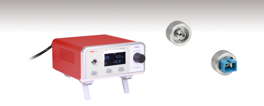
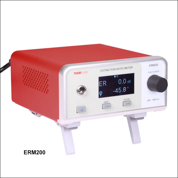
ERM200
Extinction Ratio Meter,
600 nm - 1600 nm
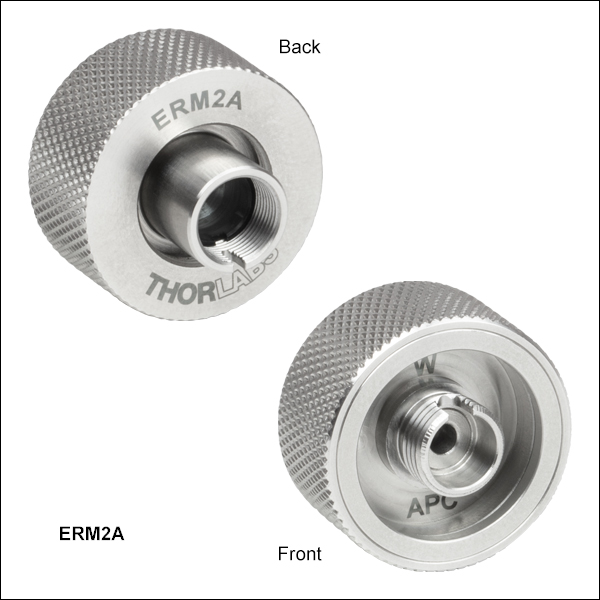
ERM2A
Wide-Key FC/APC Fiber Connector Adapter
(Not to Scale)
ERM2S
SC/PC Fiber Connector Adapter
(Not to Scale)


Please Wait
 Click to Enlarge
Features
- Polarization Extinction Ratio (PER) Measurements of Polarization-Maintaining (PM) Fibers
- Measures PER Up to 40 dB at Peak Wavelength
- Three Wavelength Ranges Cover from 400 nm - 2500 nm:
- 400 nm - 700 nm (Item # ERM210)
- 600 nm - 1600 nm (Item # ERM200)
- 1200 nm - 2500 nm (Item # ERM220)
- Control Via Front Panel Display or USB Interface
- Exchangeable Fiber Connector Adapters Sold Separately
- Supported Connectors: Wide- and Narrow-Key FC/PC, Wide- and Narrow-Key FC/APC, LC/PC, and SC/PC
Common Applications
- Optimized Coupling of Linearly Polarized Light into PM Fibers
- Alignment to Connector Key
- Pigtailing (Alignment of Laser Diodes to PM Fibers)
- Active Alignment for PM Fiber Splicing
The ERM2xx Extinction Ratio Meters measure the polarization extinction ratio (PER) and the polarization angle of polarization-maintaining (PM) fibers. These easy-to-use benchtop devices are useful in alignment applications such as connectorization of PM fibers or pigtailing of laser diodes with PM fibers. A rotating polarizer in conjunction with a photodiode for light detection provides fast and accurate measurements of the PER of PM fibers. Additionally, the polarization angle and the power of the input light beam is measured. Three units are available covering wavelengths from 400 nm to 2500 nm: 400 nm - 700 nm (Item # ERM210), 600 nm - 1600 nm (Item # ERM200), and 1200 nm - 2500 nm (Item # ERM220). For active alignment of PM Fibers, the ERM2xx devices have a Monitor Output with 0.1 V/dB conversion factor, which is compatible with our Vytran® PM Fusion Splicers.
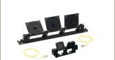
Connector Accessories
The front panel features a port that accepts exchangeable fiber connector adapters (sold separately). This enables the extinction ratio meters to measure fibers in FC/PC, FC/APC, LC/PC, and SC/PC connectors. To discuss custom connector options not available below, please contact Tech Sales. Thorlabs' ERM2xx Extinction Ratio Meters are shipped with an aperture lock on the fiber connector port to prevent damage during transport. Further details on the shipping lock can be found in the manual.
Module Control
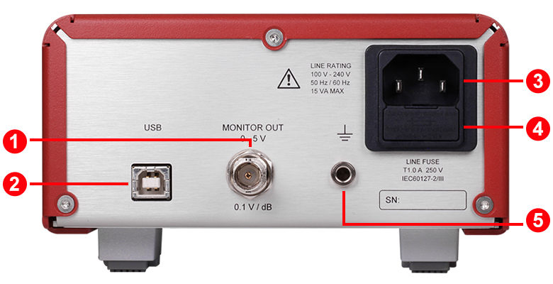
The ERM2xx devices can be controlled via the display and control knob on the front panel. The back of the extinction ratio meter includes a power inlet with a fuse compartment, a banana jack for use with a ground pin, and a BNC for monitor output. See the Front & Back Panel tab for details. The ERM2xx series can also be controlled remotely using our optical power monitor software. The features of the PC control software are highlighted in the Software tab.
All technical data are valid at 23 ± 5 °C and 45 ± 15% relative humidity (non-condensing).
| Item # | ERM210 | ERM200 | ERM220 |
|---|---|---|---|
| Wavelength Range | 400 nm - 700 nm | 600 nm - 1600 nm | 1200 nm - 2500 nm |
| Peak Wavelength | 700 nm | 1550 nm | 2300 nm |
| Maximum Input Powera | +13 dBm | +13 dBm | +8 dBm |
| PER Resolution | 0.1 dB (Display) 0.01 dB (USB) |
||
| PER Rangea | 0 to 40 dB (for +13 dBm to -12 dBm) 0 to 30 dB (for -12 dBm to -27 dBm) 0 to 20 dB (for -27 dBm to -37 dBm) |
0 to 40 dB (for +13 dBm to -12 dBm) 0 to 30 dB (for -12 dBm to -27 dBm) 0 to 20 dB (for -27 dBm to -37 dBm) |
0 to 40 dB (for +8 dBm to -12 dBm) 0 to 30 dB (for -12 dBm to -27 dBm) 0 to 20 dB (for -27 dBm to -37 dBm) |
| PER Accuracy | <0.5 dB | ||
| Polarization Angular Resolution | 0.1° (Display) 0.01° (USB) |
||
| Accuracy of Polarization Angle | <0.5° | ||
| Measuring Speed | Approximately 10 Hz | ||
| Responsivity (Click for Graph) |  Raw Data |
 Raw Data |
 Raw Data |
| Connector Type | M12 x 0.5 Thread for: ERM2F (Wide-Key, 2.2 mm FC/PC) ERM2F2 (Narrow-Key, 2.0 mm FC/PC) ERM2A (Wide-Key, 2.2 mm FC/APC) ERM2A2 (Narrow-Key, 2.0 mm FC/APC) ERM2L (LC/PC) ERM2S (SC/PC) |
||
| Monitor Output | |||
| Voltage Output | 0 V to 5 V (High-Z, Conversion Factor 0.1 V/dB) | ||
| Accuracy | ±10 mV (Typ.) ±50 mV (Max) |
||
| General | |||
| Interface | USB Type B | ||
| Display | 2.42" OLED | ||
| AC Input | Universal, 110 V to 220 V, 50/60 Hz | ||
| Power On Warm-Up Time | 15 minutes | ||
| Operating Temperature Rangeb | 5 °C to 40 °C | ||
| Storage Temperature Range | -20 °C to 40 °C | ||
| Relative Humidity | Max 80% up to 31 °C, Decreasing to 50% at 40 °C | ||
| Dimensions (W x H x D) | 153.2 mm x 85.4 mm x 188.8 mm (6.03" x 3.36" x 7.43") | ||
| Weight | 1.05 kg | ||
Click to Enlarge
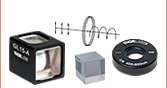
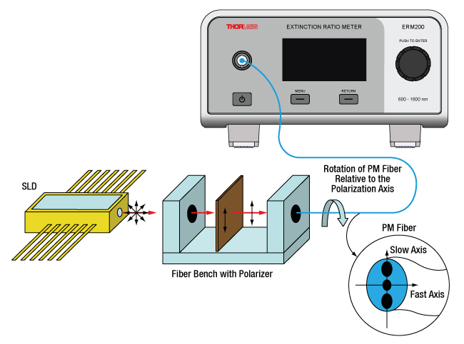
Figure 3.1 Experimental Setup to Align a PM Fiber's Slow Axis with the Transmission Axis of a Polarizer
Light Source Considerations
For common applications using the ERM2xx, Thorlabs recommends the use of a broadband light source such as Amplified Spontaneous Emission (ASE) or Superluminescent Diodes (SLD) rather than a narrowband source to simplify the alignment procedure. Narrowband sources can be used with additional steps. For more details, see the manual.
Example: Aligning a PM Fiber Patch Cable to a Polarizer's Transmission Axis
A PM fiber patch cable can be aligned to the transmission axis of a polarizer using one of the ERM2xx Extinction Ratio Meters, an SLD, and a FiberBench equipped with a polarizer and a FiberPort by following the procedure below:
- Connect the output connector of the fiber under test to the fiber adapter on the ERM2xx unit and turn on power.
- Connect the SLD to the input of the FiberBench with the polarizer.* This will produce polarized light at the output of the FiberBench to which the PM patch cable will be aligned.
- Connect the input of the PM fiber into the output of the FiberBench.
- Navigate through the menu items until the ER value is shown on the digital display. Consult the manual for details.
- Rotate the input of the PM fiber relative to the polarizer's transmission axis mounted in the FiberBench until a maximum ER value is displayed. At the point of maximum ER, the slow axis of the fiber patch cable is aligned with the transmission axis of the polarizer in the FiberBench.
*The coupling optics required are dependent on the light source and are not illustrated here.
Front Panel
Back Panel
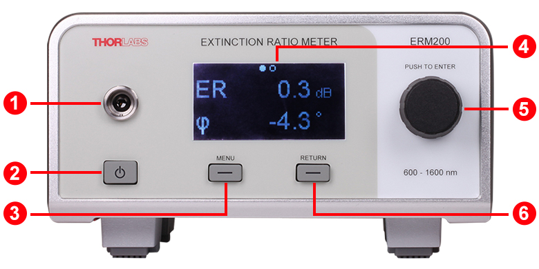
| Callout | Description |
|---|---|
| 1 | Fiber Adapter Connection Port |
| 2 | Power Button |
| 3 | Menu Selection Button |
| 4 | Display |
| 5 | Rotary Navigation and Control Knob |
| 6 | Return Button |
| Callout | Description |
|---|---|
| 1 | Monitor Out (BNC Female, 0 to 5 V) |
| 2 | USB Type B Connector |
| 3 | IEC-60320 C14 Power Inlet |
| 4 | Fuse Compartment |
| 5 | Banana Jack for Chassis Ground |
Item #s ERM200, ERM210, and ERM220 include the following:
- Extinction Ratio Meter
- USB 2.0 Cable Type A-B, 2 m
- Region-Specific Power Cord
- Test Report
- Quick Reference Manual
The ERM2xx Series Extinction Ratio Meters can be remotely controlled with the OPM software or the ERM200 Series Driver Package, which features drivers for third-party development and is included with the OPM software package.
Compatible Power Meters
- Consoles:
- PM100A Analog Power and Energy Meter Console
- PM200 Legacy Touch Screen Power and Energy Meter Console
- PM100D Legacy Digital Power and Energy Meter Console
- PM100D2 and PM100D3 Digital Power and Energy Meter Consoles (Version 7.0)
- PM400 Capacitive Touchscreen Power and Energy Meter Console
- PM5020 Dual-Channel Benchtop Optical Power and Energy Meter Console (Version 4.0 or Later)
- Complete Power Meters:
- PM160, PM160T, and PM160T-HP Wireless Handheld Power Meters with Bluetooth® Technology
- PM16 Series Compact USB Power Meters
- PM60 and PM61 Fiber Optic Power Meter Series (Version 6.0 or Later)
- Interfaces:
- PM101 Series Power Meter Interfaces with External Readout (Version 2.0 or Later)
- PM102 Series Power Meter Interfaces with External Readout (Version 2.1 or Later)
- PM103 Series Power Meter Interfaces with External Readout (Version 3.0 or Later)
- PM100USB USB Interface Digital Power and Energy Meter
Other Compatible Devices
- ERM2xx Series Extinction Ratio Meters
- SPCNT Single Photon Counting Device
- TSP01 USB Temperature and Humidity Data Logger
- TSP-TH Additional Temperature Probe
- WM202 Wavelength Meter
Optical Parameter Monitor
The Optical Parameter Monitor GUI software features readout from up to eight power meters or other compatible devices, or remote wireless operation.
For details on specific software features, please see the user manual.
Users interested in the legacy Power Meter Software can find it by visiting the software page.
The PM100D2 and PM100D2 are only compatible with version 7.0. The PM101 Series Power Meters are only compatible with version 2.0 or later. The PM102 Series Power Meters are only compatible with version 2.1 or later. The PM103 Series Power and Energy Meters are only compatible with version 3.0 or later. The PM5020 Console is only compatible with version 4.0 or later. The PM60 and PM61 Power Meter Series are only compatible with version 6.0 or later.
Optical Parameter Monitor GUI Software for Touchscreen, Handheld, and USB-Interface Power Meters
Features
- Operate up to Eight Devices Simultaneously
- Record and Analyze Measurements in Real Time
- Intuitive Analog Display and Graphing Modes
- Configurable Long-Term Data Logging
- Also Supports Position Measurements with Thermal Position & Power Sensors
- Compatible with USB, Bluetooth®, Ethernet, and Serial Connections
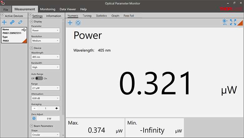
The Optical Parameter Monitor (OPM) software GUI enables seamless control of up to eight compatible devices that are connected via USB, RS232, Ethernet, or Bluetooth®,a wireless technologyb. The latest software, firmware, drivers, and utilities for these power meters can be downloaded here.
Multiple data measurement and analysis functions are integrated into the GUI package. The interface offers a user-friendly design with minimal use of color and low brightness that is ideal for use in dark lab environments while wearing laser safety glasses. Measured data can be displayed in real time as a simulated analog needle, digital value, line graph, or bar graph. Continuously logged and short-term measurements can be recorded for data viewing and analysis at a later point. A built-in statistics mode analyzes measured data and updates continuously to reflect new measurements within the pre-determined measurement period. Beam position measurements are also supported when used with our thermal position and power sensors and a compatible power meter.
The OPM software package installs the GUI, which then can be used to control the touchscreen, handheld, or USB-interface power meters and other compatible devices. Firmware updates for supported devices are also available. Programming examples and drivers for interfacing with our power and energy meter consoles using LabVIEW, C/C++, Visual C#, and Python are installed with the software.
Please note that the OPM Software uses different drivers than the Power Meter Utilities Software and Thorlabs recommends using the new driver TLPM.dll. For users who wish to use the legacy Power Meter Software or use custom software designed using the older PM100D.dll driver, a Power Meter Driver Switcher program is included for easy swapping of the installed driver between the two versions.
- Bluetooth is a registered trademark of Bluetooth Sig, Inc.
- The PM100D3, PM61 Series, PM160, PM160T, and PM160T-HP power meters are equipped with Bluetooth connections.
Click to Enlarge
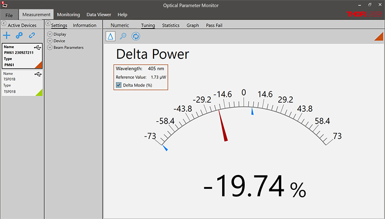
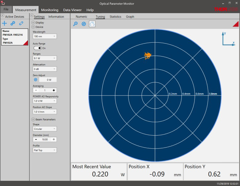
Figure 149B Tuning Mode
Simulated analog needle and digital measurement value provided. Delta Mode, enabled here, shows the fluctuation range during the measurement period.
Click to Enlarge
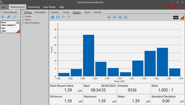
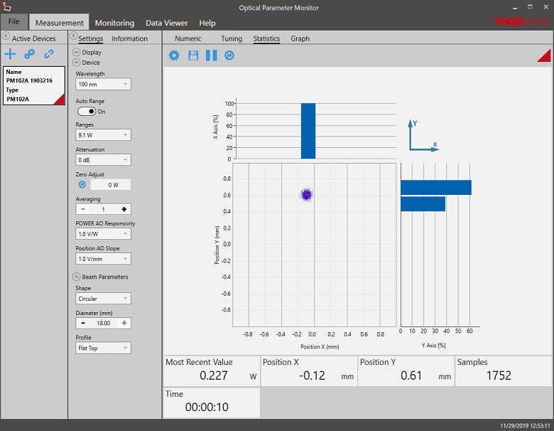
Figure 149C Statistics Mode
Calculate numerical statistics for a pre-determined measurement period. The panel displays the analyzed values in a bar graph and the results as numerical values.
Click to Enlarge
Figure 149D Position Tuning Mode
Tuning mode can be used with a thermal position and power sensor to aid in beam alignment, if the connected power meter supports it.
Click to Enlarge
Figure 149E Position Statistics Mode
Statistics mode also provides aggregate information for thermal position and power sensors, if they are supported.
Click to Enlarge
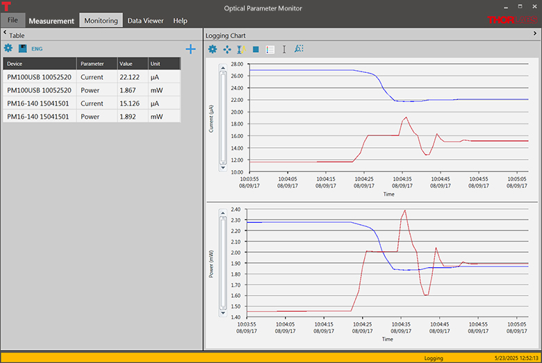
Figure 149F Monitoring Mode
Enable long-term measurement and simultaneous recording from up to eight power meters. Save data as .csv files for later processing while measurement results are displayed in a graph in real time.
| Posted Comments: | |
Vladimir Lavrov
(posted 2025-07-16 10:51:11.087) Hi!
Do you have a E2000 adapter for the PER meter?
Is it possible to order that custom thing? sacosta
(posted 2025-07-17 07:47:17.0) Thanks for reaching out. Currently we do not offer extinction ratio meters for use with E2000/PC connectors, but we will consider your request for future development. We offer a mating sleeve for E2000/PC to FC/PC connectors, ADAE2, that you could in principle use, but we do not have information about how the specifications for error would change in this case. I have contacted you via email to discuss further. user
(posted 2024-11-19 17:27:19.223) Do you have test data that support the PER accuracy of the ERM200 at 1300nm? What guarantees the PER spec across the entire wavelength range? Is this instrument based on a polarizing beam splitter cube? hkarpenko
(posted 2024-11-20 11:42:08.0) Dear customer,
thank you for your feedback. The extinction ratio meter is based on a rotating polarizer and photodiode. The wavelength range is specified mainly on these two components and the accuracy of the PER is specified as <0.5dB for the whole range. I will contact you directly to discuss this further with you. user
(posted 2024-03-19 15:53:35.387) Is there any chance to get a python wrapper for the ERM200 libraries? GBoedecker
(posted 2024-03-20 08:41:54.0) Thank you for you feedback! I will send you the Python wrapper. Besides that, we have a Python example on Github https://github.com/Thorlabs |

 Zoom
Zoom- Control Via Front Panel Display and Control Knobs or USB Interface
- Three Models Cover Wavelengths from 400 nm to 2500 nm
- Port for Exchangeable Fiber Connector Adapter (Sold Separately)
The ERM2xx Extinction Ratio Meters measure the polarization angle and extinction ratio (ER) of polarization-maintaining (PM) fibers and are useful in alignment applications such as connectorization of PM fibers or pigtailing of laser diodes with PM fibers.
Note: To use these extinction ratio meters, at least one exchangeable Fiber Connector Adapter (available below) must be purchased separately.

 Zoom
Zoom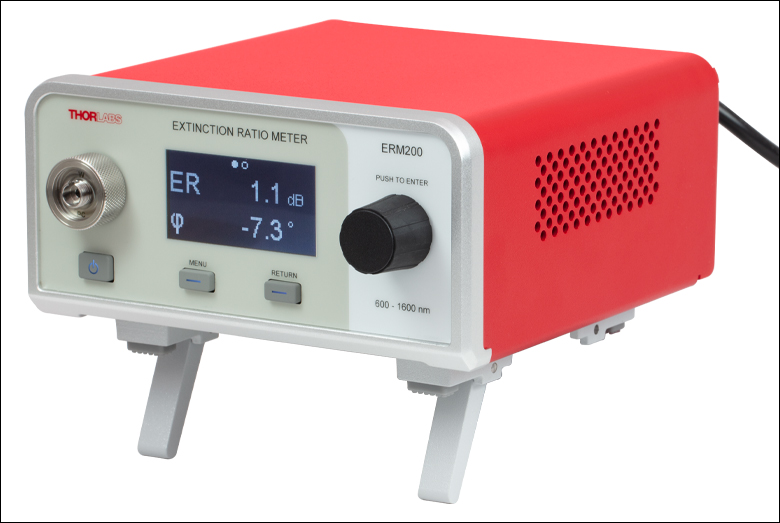
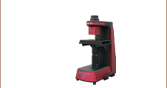
Click to Enlarge
Figure G2.1 ERM200 with ERM2F Adapter
- Adapters to Enable Measurement of Various PM Fibers with ERM2xx Extinction Ratio Meters
- Six Options Available
To accommodate different PM fiber connectors, Thorlabs offers six different adapters for the extinction ratio meters sold above. Each adapter can be directly mounted to the device via the fiber connector port on the front panel as shown in Figure G2.1.