 Products Home / Optical Elements / Optical Mirrors / Ultrafast Mirrors for Pulsed Lasers / Chirped Mirrors for Dispersion Compensation of Ultrafast Pulses
Chirped Mirrors for Dispersion Compensation of Ultrafast Pulses
- Corrects for Dispersive Optical Elements
- Low AOI Allows Multiple Reflections Between Mirrors
- R > 99% for 650 - 1050 nm or 700 - 1000 nm
- Complementary Mirror Pair Available
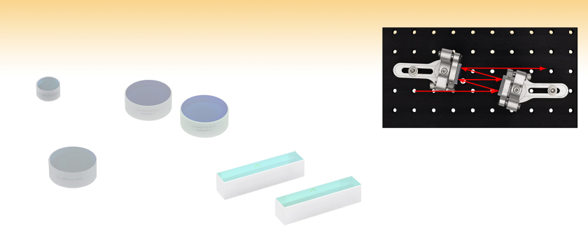
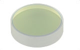
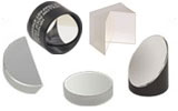
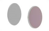
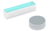
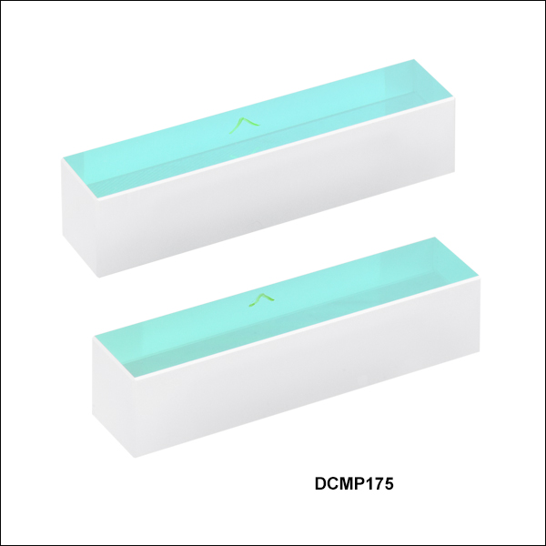
DCMP175
53.0 mm x 12.0 mm, Designed for Multiphoton Microscopy
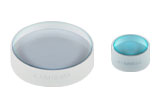
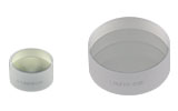
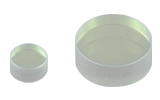
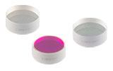
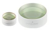
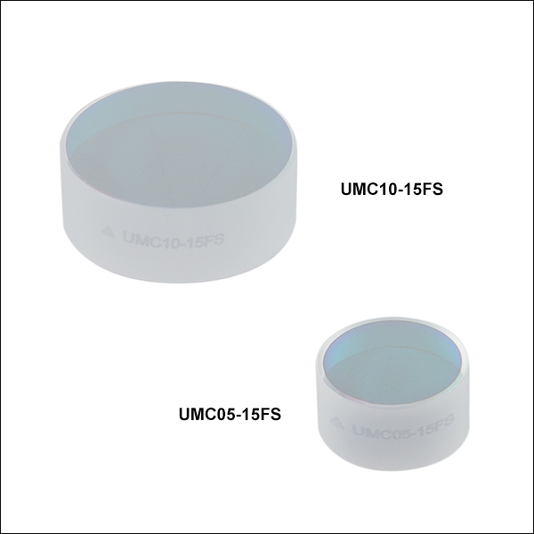
UMC10-15FS
Ø1", Compensates for
1.5 mm of Fused Silica
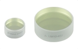
UMC05-15FS
Ø1/2", Compensates for
1.5 mm of Fused Silica
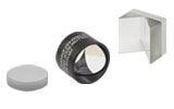
Application Idea
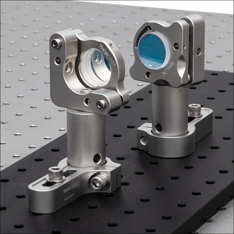
UMCP10-3FS1 Chirped Mirror Pair in POLARIS-K1E2 Mounts Set Up in a Multi-Pass Configuration
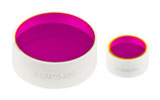
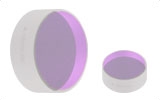
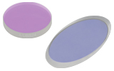
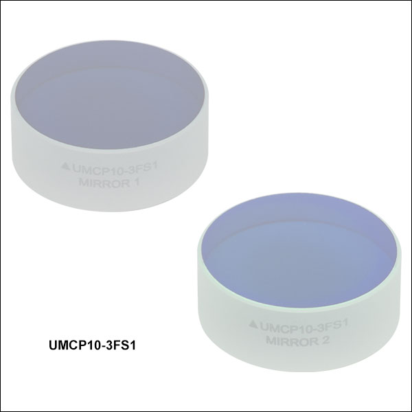
UMCP10-3FS1
Complementary Ø1" Mirror Pair, Compensates for
3.0 mm of Fused Silica


Please Wait
Click to Enlarge
Figure 1.1 Two UMCP10-3FS1 chirped mirrors in POLARIS-K1E2 mirror mounts, configured for two reflections per mirror at a 10° AOI. Glue-in mounts with a clear edge, like the POLARIS-K1C4 mount, can be used to maximize the number of reflections off each mirror.
Features
- Chirped Mirrors Designed for Compensating Group Delay Dispersion (GDD) Introduced by:
- UMCx-15FS: Transmission Through 1.5 mm of Fused Silica (per Mirror)
- UMCP10-3FS1: Transmission Through 3.0 mm of Fused Silica (per Mirror Pair)
- DCMP175: Transmission Through 4.8 mm of Fused Silica (per Mirror)
- High Reflectance and Low Angle of Incidence (AOI) Allow Multiple Reflections for Increased Compensation
Thorlabs' Chirped Mirrors, also known as dispersion-compensating mirrors, correct for the pulse stretching that occurs when ultrashort pulses propagate through dispersive media. Our chirped mirrors are designed to compensate for transmission through fused silica, the most common substrate for ultrafast optics, and are offered in three types: individual round mirrors, a complementary round mirror pair (Item # UMCP10-3FS1) designed for higher fidelity compression of ultrafast pulses and ideal for multi-pass configurations, and rectangular mirrors. Chirped mirrors can also be used for compressing ultrafast pulses prior to using them for second harmonic generation (SHG), optical parametric oscillation (OPO), optical parametric amplification (OPA), and other nonlinear interactions, as well as to compensate for the long path lengths found in multiphoton microscopes. The complementary mirror pair is ideal for applications with both broadband and tunable lasers, as the GDD ripples introduced by the mirror coatings are compensated for. The individual mirrors (Item # UMCxx-15FS) are less suited for tunable narrowband lasers, as the GDD changes dramatically as the laser pulse is scanned through the operation range. For a performance comparison of the individual chirped mirrors and the complementary chirped mirror pair, see the GDD Compensation tab.
Since a femtosecond laser pulse consists of many different wavelengths, pulse stretching (a lengthening of the temporal intensity profile) will occur when the pulse passes through a dielectric medium, like glass. This stretching is caused by dispersion, the wavelength dependence of the refractive index of transmissive optical elements. In most dispersive materials, the index of refraction for shorter wavelengths is larger than the index of refraction for longer wavelengths, causing shorter wavelengths to be delayed. These mirrors are specifically designed so that longer wavelengths experience larger group delay dispersion (GDD) than shorter wavelengths, compensating for the GDD caused by transmission through dispersive media. For more information on group delay and group delay dispersion, please see the GDD Compensation tab. Our Chromatis™ dispersion measurement system can characterize the dispersive properties of optical components by measuring group delay, group delay dispersion, third-order dispersion, and fourth-order dispersion. For additional information on group delay and group delay dispersion, see the Operations tab in the Chromatis™ system web presentation.
The coatings on these mirrors are deposited onto the surface using ion beam sputtering (IBS). This highly repeatable and controllable technique results in durable thin film coatings. Designed with ultrafast laser applications in mind, these coatings have a high reflectance, high damage thresholds, and are measured to match their theoretical GDD performance well using our Chromatis™ system.
Using Thorlabs' chirped mirrors at their designed AOI will result in optimal performance, however they can be used at smaller angles of incidence. While designed to correct for the positive GDD caused by fused silica, all Thorlabs' chirped mirrors can compensate for positive GDD introduced by other materials. While the GDD of other common optical glasses can be compensated with these mirrors, the higher order dispersion terms (e.g., third-order dispersion) will not be perfectly compensated. This may or may not be a concern depending on the pulse bandwidth. For Thorlabs' full selection of optics for ultrafast applications, please see the Ultrafast Optics tab.
| Specifications | ||||
|---|---|---|---|---|
| Item # | UMC05-15FS | UMC10-15FS | UMCP10-3FS1 | DCMP175 |
| Wavelength Range | 650 - 1050 nm | 650 - 1050 nm | 700 - 1000 nm | |
| Reflectance over Wavelength Range | Rabs > 99.5% per Mirror | Rabs > 99.8% per Mirror | Ravg > 99% per Mirror | |
| Reflectance Data (Click for Graph) | Raw Data |
Raw Data |
Raw Data |
|
| Group Delay Data (Click for Graph) | Raw Data |
Raw Data |
Raw Data |
|
| Group Delay Dispersion (GDD) | -54 fs2 at 800 nm per Mirror | -108 fs2 at 800 nm per Mirror Pair | -175 fs2 at 800 nm per Mirror | |
| Group Delay Dispersion (GDD) Data (Click for Graph) | Raw Data |
Raw Data |
Raw Data |
|
| Laser-Induced Damage Threshold | 0.07 J/cm2 (800 nm, 43.2 fs FWHM, S-Pol, 10 000 Pulses)a |
0.05 J/cm2 (800 nm, 49 fs FWHM, P-Pol, 10 000 Pulses)a |
0.10 J/cm2 (800 nm, 100 fs) |
|
| Size | Ø1/2" | Ø1" | Ø1" | 53.0 mm x 12.0 mm (2.09" x 0.47") |
| Diameter Tolerance | +0.00 / -0.10 mm | +0.00 / -0.10 mm | N/A | |
| Thickness | 6.35 mm (0.25") | 9.5 mm (0.37") | 9.5 mm (0.37") | 12.0 mm (0.47") |
| Thickness Tolerance | ±0.10 mm | ±0.20 mm | ±0.20 mm | - |
| Clear Aperture | >80% of Diameter | >80% of Diameter | At Least 8 mm x 50 mm | |
| Angle of Incidence (AOI) | 10° | 10° | 8° | |
| Surface Flatnessb | λ/4 at 632.8 nm Over Clear Aperture | λ/4 at 632.8 nm Over Clear Aperture | λ/10 at 633 nm Over Any Ø8 mm in the Clear Aperture | |
| Surface Quality (Front Surface) | 15-5 Scratch-Dig | 15-5 Scratch-Dig | 10-5 Scratch-Dig | |
| Back Surface | Polished | Polished | - | |
| Substrate | Fused Silica | Fused Silica | Fused Silica | |
| Parallelism | ≤3 arcmin | ≤3 arcmin | - | |
How Dispersion Compensation Works
Laser pulses experience dispersion when transmitting through dispersive media. Most dispersive materials have a positive group delay dispersion in the 650 - 1000 nm wavelength range. In a positively dispersed pulse, the shorter wavelengths contained within the pulse travel slower than the longer wavelengths (that is, blue travels slower than red), while the opposite occurs for a negatively dispersed pulse (that is, red travels slower than blue). In either case, the laser pulse at the sample is lengthened in duration, leading to reduced peak intensity.
Thorlabs' chirped mirrors apply negative group delay dispersion to pulses with wavelengths in the ranges of 650 - 1050 nm (Item #s UMCxx-15FS and UMCP10-3FS1) or 700 to 1000 nm (Item # DCMP175). While designed to correct for the positive GDD caused by fused silica in those wavelength ranges, these mirrors can compensate for positive GDD introduced by other materials. For more information on the performance of these mirrors, please see the Specs tab.
Figure 3.1 shows an example of compensating positive group delay dispersion using chirped mirrors. The chirped mirrors can be placed either before or after the dispersive element to either precompensate or compensate for the group delay dispersion, respectively.
Figure 3.1 Example of Compensating Positive GDD Using Chirped Mirrors
Chirped Mirror Comparison
For broadband chirped mirrors, there are always GDD oscillations caused by the coating design, which cause satellite pulses. When two identical mirrors are used, the oscillations imparted on the pulse due to the coating of both mirrors are in phase and therefore the satellite pulses constructively interfere (see Figure 3.2). However, the coatings for the complementary mirror pair (Item # UMCP10-3FS1) are designed so the oscillations are out of phase and destructively interfere, nearly eliminating the satellite pulses. Figures 3.3 and 3.4 show a comparison of temporal profiles of pulses when using two identical UMCxx-15FS mirrors or a UMCP10-3FS1 complementary chirped mirror pair to compensate for GDD introduced by transmission through 15 mm of fused silica.
Click to Enlarge
Figure 3.2 Comparison of Pulse Propagation when Using Identical Chirped Mirrors and a Complementary Chirped Mirror Pair
Click to Enlarge
Figure 3.3 Comparison of UMCxx-15FS chirped mirrors and a UMCP10-3FS1 complementary chirped mirror pair. The temporal profiles of the original pulse, a pulse after transmission through 15 mm of fused silica (such as a UFPBS10A beamsplitter), a pulse after 15 mm of fused silica and two UMCxx-15FS mirrors (5 bounces per mirror), and a pulse after 15 mm of fused silica and a UMCP10-3FS1 pair (5 bounces off the mirror pair) are shown. When using the UMCP10-3FS1 chirped mirror pair, the temporal profile is retained, and the satellite pulses are suppressed.
Click to Enlarge
Figure 3.4 Comparison of UMCxx-15FS chirped mirrors and a UMCP10-3FS1 complementary chirped mirror pair. The temporal profiles of the original pulse, a pulse after transmission through 15 mm of fused silica (such as a UFPBS10A beamsplitter), a pulse after 15 mm of fused silica and two UMCxx-15FS mirrors (5 bounces per mirror), and a pulse after 15 mm of fused silica and a UMCP10-3FS1 pair (5 bounces off the mirror pair) are shown. When using the UMCP10-3FS1 chirped mirror pair, the temporal profile is retained, and the satellite pulses are suppressed.
| Posted Comments: | |
Hyun Sung Lee
(posted 2025-06-20 15:31:19.71) Dear THORLABS,
I found chirped mirror UMC05-15FS in your website, and I want to know a raw data for the phase graph of mirror, not the gdd graph.
Is it possible to get the data?
Thank you,
Hyun Sung Lee EGies
(posted 2025-06-30 01:09:08.0) Thank you for contacting Thorlabs. I have reached out to you directly regarding the theoretical phase data for the UMC05-15FS. To request additional specs and data, you can email us at techsupport@thorlabs.com. user
(posted 2025-02-21 04:22:03.39) 有不同波长处的GDD曲线吗 cdolbashian
(posted 2025-03-20 01:36:08.0) Thank you for reaching out to us with this inquiry. I have contacted you directly to share the GDD data as you requested. Lukasz Piatkowski
(posted 2023-10-09 10:27:14.27) Hi,
I'm looking for dispersion compensating optics to deal with dispersion in the range 600-700 nm in the laser pulses coming from a white light laser source (NKT Fianium). What is the reflectivity/dipsersion compensation characteristic of your DCMP175 in the mentioned range?
With best wishes,
Lukasz cdolbashian
(posted 2023-10-20 10:37:27.0) Thank you for reaching out to us with this inquiry. Unfortunately, these mirrors are not meant to be used <650nm as this is outside the design wavelength range. The in-range performance can be found in the "graphs" tab above. In the case you do decide to use them within this range, you will likely experience inconsistent performance from unit to unit, due to the above design consideration. XinWei Yi
(posted 2023-04-01 16:00:55.72) I want to know the group delay dispersion (GDD) curve of UMC10-15FS at zero Angle of incident. cdolbashian
(posted 2023-04-26 10:01:00.0) Thank you for reaching out to us with this inquiry. Unfortunately we do not have such data to share. we would estimate a redshift of about 2% with respect to the values we have posted for the 10° AOI. Cheng Zong
(posted 2022-03-18 13:30:38.39) Hi, I find the DCMP175 surface is dusty. How to clean it? Can I use methanol or acetone to clean it? ksosnowski
(posted 2022-03-22 05:33:05.0) Hello Cheng, thanks for reaching out to Thorlabs. We recommend light dusting with clean, dry air first to remove the largest particles. If solvent is needed to wipe the surface, you can use acetone, methanol, or isopropanol to clean this as the chirped mirror pair is not cemented. We offer lens wipes MC-5 and cleaning accessories to aid in this as well. It may be slightly easier to avoid streaks with isopropanol, as it dries slightly slower allowing a slower, more even wiping motion. Hendrik Wrigge
(posted 2021-12-08 08:31:59.49) Using the UMC10-15FS mirrors, I noticed a slight ellipticity in polarisation after my mirror compressor. The initial beam bevore the mirrors is strictly linear polarized.
Inside the compressor, I use 16 reflections on the UMC10-15FS.
Is this a standart behavior of your mirror or do you have any coment on this?
Thank you in advance cdolbashian
(posted 2021-12-22 04:29:22.0) Thank you for contacting us here at Thorlabs. We have not characterized the reflection-induced-polarization states for these mirrors. Theoretically though, if your polarization state was not completely within, or orthogonal to, the incident plane, you may see a slight ellipticity in your reflected beam, especially after 16 bounces. Based on our discussion it seemed that there was a bit of misalignment between the incident plane and the direction of linear polarization (~.5deg). Correcting this error solved the problem which you were seeing. Thank you again for reaching out to us and allowing me to help you work through this problem. Audrius z
(posted 2020-09-30 08:28:56.68) Hello, could please send me the GDD curve for these chirped mirrors?
Best YLohia
(posted 2020-10-01 03:57:11.0) Hello, thank you for contacting Thorlabs. Which specific mirror are you referring to? One can calculate this from the raw group delay data (found on the Graphs tab) by taking the derivative. I have reached out to you directly to discuss this further. Ondrej Novak
(posted 2019-10-11 17:48:54.953) Dear colleagues, could you please provide us with a graph of DCMP175 GDD compensation performance over different wavelength? Such curve would be extremely helpful. I am especially interested in wavelengths from 920nm to 1040nm. How much fs2 can be compensate per single bounce? Thank you.
Ondrej YLohia
(posted 2019-10-22 10:12:15.0) Hello Ondrej, thank you for contacting Thorlabs. The GDD for the DCMP175 is nominally -175 fs^2 at 800 nm but it changes a little with wavelength and has fairly large oscillations. I have reached out to you directly with some GDD data that we have up to 1000 nm. The oscillations become very large outside the design range. That's typical for all dielectric coatings, not just these chirped mirrors. We do not recommend using these at >1000 nm. yuezhu
(posted 2017-12-18 12:46:27.343) Can I use chirped mirrors in optical coherence tomography system?
How about https://www.thorlabs.com/newgrouppage9.cfm?objectgroup_id=3242 ?
Which one is better? tfrisch
(posted 2018-03-22 12:16:19.0) Hello, thank you for contacting Thorlabs. Chirped mirrors and dispersion compensating prisms are both used to adjust for chromatic dispersion. Which one is better suited for your application will depend on how you intend to use these. I will contact you directly about your application. dtorchin
(posted 2017-12-06 18:32:00.957) Individual chirped mirrors have GD oscillations as a function of wavelength. Is DCMP175 sold as a pair whose oscillations cancel? llamb
(posted 2018-03-01 08:12:47.0) Hello, thank you for contacting Thorlabs. DCMP175 is indeed sold as a pair of mirrors. The oscillations will not cancel, but each reflection will add to the Group Delay Dispersion. The mirrors can be adjusted to increase/decrease the number of reflections, thus increasing/decreasing the GDD as needed for the application. pedro.oliveira
(posted 2017-10-24 18:52:36.55) Dear Sir/Madam,
I would like to have the data for the reflectance and the GD for DCMP175?
Many thanks,
Pedro Oliveira tfrisch
(posted 2017-10-30 01:55:22.0) Hello, thank you for contacting Thorlabs. We will reach out to you directly with theoretical data in tabular form that can be used for your calculations. t.wills
(posted 2017-01-27 05:41:00.78) Dear Thorlabs,
Do you have a number available for the GDD per reflection at 940nm? This would be the wavelength I need to use.
I am confused by the graph showing 'GD' versus wavelength - 'GD' appears to go positive at wavelengths >850nm, which means the mirror wouldn't work for pre-compensation (but I suspect I haven't understood the graph).
Many thanks,
Tom tfrisch
(posted 2017-02-17 02:34:05.0) Hello, thank you for contacting Thorlabs. GD and GDD are related by a derivative. I will contact you directly with more details, but the zero of GD is chosen only as a reference. user
(posted 2013-08-23 10:41:42.49) Is there a recommended maximum distance between the mirrors, a maximum incidence angle or a maximum number of reflexions to consider? Is there an app note or recommendations on using these? Thank you. jlow
(posted 2013-08-29 13:18:00.0) Response from Jeremy at Thorlabs: The recommended maximum angle of incidence (AOI) is about 7°. The correct mirror distance depends on the number of bounces needed. Depending on the wavelength of the laser used, the tolerable AOI can be different as well. We have some plots (for s- and p-polarization) showing the evolution of the calculated GDD in the specified wavelength range as a function of AOI. As a general rule of thumb, the maximum AOI is smaller if the laser wavelength is longer. For example, around 20° AOI might be useable for 750-800nm light but around 10° AOI might be useable for 900-950nm light. However, it should be noted that the performance is not guaranteed for large AOIs. Since you did not leave your e-mail address, can you contact techsupport@thorlabs.com please? We can discuss about this further via e-mail. tcohen
(posted 2012-05-16 13:45:00.0) Response from Tim at Thorlabs: Thank you for contacting us Jan Metje! Our baseline LIDT for the DCMP is 0.1J/cm^2 for 100fs pulses at 100Hz. Please note that for shorter pulses and higher repetition rates the damage threshold will be smaller. jan.metje
(posted 2012-05-15 07:57:14.0) Dear Sir or Madam,
do you know the damage threshold of this dispersion comensating mirror set?
Kind regards,
Jan Metje bdada
(posted 2011-10-12 19:22:00.0) Response from Buki at Thorlabs:
The DCMP175 Dispersion-Compensating Mirrors can be mounted in the KM100C Kinematic Cylindrical Lens Mount. The mount accepts any cylindrical or rectangular optic up to 65 mm tall.
The mount can be attached to any of Thorlabs' Ø1/2" TR Series posts, which feature an #8-32 (M4) tapped hole. Alternatively, the KM100C mount can also be attached to an RS1.5P Ø1" Pedestal Pillar Post, which has a height of 1.5", and can be secured to the breadboard using a CF125 Clamping Fork.
Alternatively, these mirrors can be mounted in the Kinematic Grating Mount Adapter,KGM20, KGM40, or KGM60 which is compatible with Ø1", front-loading, unthreaded mirror mounts.
Please contact TechSupport@thorlabs.com if you have further questions. zacarias.garcia
(posted 2011-10-12 08:52:58.0) Could you please tell us how and where to install these mirrors ? |
Thorlabs offers a wide selection of optics optimized for use with femtosecond and picosecond laser pulses. Please see below for more information.
| Low-GDD Mirrors | |||||
|---|---|---|---|---|---|
 |
 |
 |
 |
 |
 |
| 355 - 445 nm | 460 - 590 nm | 700 - 930 nm | 970 - 1150 nm | 1400 - 1700 nm | 1760 - 2250 nm |
| Dielectric Mirror | High-Power Mirrors for Picosecond Lasers |
Metallic Mirrors | Low-GDD Pump-Through Mirrors |
||
|---|---|---|---|---|---|
 |
 |
 |
 |
 |
 |
| Dual-Band Dielectric Mirror, 400 nm and 800 nm |
Ytterbium Laser Line Mirrors, 250 nm - 1080 nm |
Ultrafast-Enhanced Silver Mirrors, 750 - 1000 nm |
Protected Silver Mirrors, 450 nm - 20 µm |
Unprotected Gold Mirrors, 800 nm - 20 µm |
Pump-Through Mirrors, 1030 - 1080 nm and 940 - 980 nm |
| Deterministic GDD Beamsplitters |
Low-GDD Harmonic Beamsplitters |
Low-GDD Polarizing Beamsplitters |
β-BBO Crystals | Dispersion-Compensating Optics | |
|---|---|---|---|---|---|
 |
 |
 |
 |
 |
 |
| Beamsplitters & Windows, 600 - 1500 nm or 1000 - 2000 nm |
Harmonic Beamsplitters, 400 nm and 800 nm or 500 nm and 1000 nm |
High-Power, Broadband, High Extinction Ratio Polarizers, 700 - 1300 nm |
β-BBO Crystals for Second Harmonic Generation |
Dispersion-Compensating Mirrors, 650 - 1050 nm |
Dispersion-Compensating Prisms, 700 - 900 nm |

 Zoom
Zoom Click to Enlarge
Click for Data
Figure G1.1 Theoretical group delay dispersion of UMCxx-15FS chirped mirrors with the GDD of -1.5 mm of fused silica overlaid.
- >99.5% Absolute Reflectance from 650 to 1050 nm per Mirror
- Group Delay Dispersion (GDD) per Mirror: -1.5 mm of Fused Silica
- Clear Aperture: >80% of Diameter
- 10° AOI
- Designed for Pulses with Spectral Bandwidth >50 nm FWHM
Thorlabs' UMC05-15FS and UMC10-15FS chirped mirrors feature >99.5% absolute reflectance over the 650 - 1050 nm wavelength range per mirror. The coating is engineered such that each reflection compensates for the dispersion introduced by 1.5 mm of fused silica over the entire range. For example, at 800 nm, 1.5 mm of fused silica introduces a GDD of -54 fs2; the coating of the mirrors is engineered so that the average GDD per mirror matches that (See Figure G1.1). The 10° AOI allows these mirrors to perform similarly for both s- and p-polarized light and is ideal for a compact setup where multiple reflections are needed. For more information on the performance of these mirrors, please see the Specs tab.
Mounting Options
The Ø1/2” mirror is 6.35 mm thick, while the Ø1” mirror is 9.5 mm thick. To maximize the clear edge for multi-pass configurations, we recommend mounting the UMC105-15FS in a POLARIS-K05C4 glue-in mirror mount, and the UMC10-15FS in a POLARIS-K1C4 kinematic glue-in mirror mount.

 Zoom
Zoom Click to Enlarge
Click for Data
Figure G2.1 Theoretical group delay dispersion for a UMCP10-3FS1 complementary chirped mirror pair in p-polarization with the GDD of -3.0 mm of fused silica overlaid.
- Complementary Chirped Mirror Pair Designed for Ultrafast Pulses
- >99.8% Absolute Reflectance from 650 to 1050 nm per Mirror
- Group Delay Dispersion (GDD) per Mirror Pair: -3.0 mm of Fused Silica
- Clear Aperture: >80% of Diameter
- 10° AOI
- Designed for Use with Broad or Narrow Bandwidth Ultrafast Pulses
Thorlabs' UMCP10-3FS1 complementary chirped mirror pair is designed for higher fidelity compression of ultrafast pulses. The mirrors feature >99.8% absolute reflectance over the 650 - 1050 nm wavelength range per mirror. For a performance comparison of this complementary chirped mirror pair with individual chirped mirrors (Item # UMCxx-15FS), see the GDD Compensation tab. The mirror coatings are engineered such that each reflection off the mirror pair compensates for the dispersion introduced by transmission through 3.0 mm of fused silica over the 650 - 1050 nm range. For example, at 800 nm, 3.0 mm of fused silica introduces a GDD of -108 fs2; the coating of the mirrors is designed so that the average GDD per mirror pair matches that (See Figure G2.1). The 10° AOI allows these mirrors to perform similarly for both s- and p-polarized light and is ideal for a compact setup where multiple reflections are needed. For more information on the performance of these mirrors, please see the Specs tab.
Mounting Options
The mirrors are 9.5 mm thick. To maximize the clear edge for multi-pass configurations, we recommend mounting the UMCP10-3FS1 mirrors in POLARIS-K1C4 kinematic glue-in mirror mounts.

 Zoom
Zoom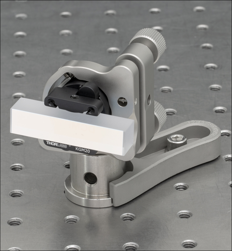
Click to Enlarge
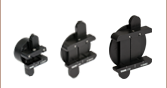
Figure G3.1 Single DCMP175 Mirror Mounted Using a KGM20 Mount Adapter
- >99% Average Reflectance from 700 to 1000 nm per Mirror
- Group Delay Dispersion (GDD) per Mirror: -4.8 mm of Fused Silica
- Coated Surface Dimensions: 50 mm x 8 mm
- 8° AOI
- Designed for Pulses with Spectral Bandwidth >50 nm FWHM
- Sold in Packs of 2
The DCMP175 consists of a pair of rectangular optics with >99% average reflectance over the 700 - 1000 nm wavelength range per mirror. These mirrors are designed to integrate with multiphoton microscopy setups, which typically include long path lengths through highly dispersive glass. For example, at 800 nm, 4.8 mm of fused silica introduces a GDD of -175 fs2; the coating of the mirrors is engineered so that the average GDD per mirror matches that. The 8° AOI allows these mirrors to perform similarly for both s- and p-polarized light, and is ideal for a compact setup where multiple reflections are needed.
Mounting Option
As shown in Figure G3.1, these mirrors can be mounted in the Kinematic Grating Mount Adapter, which is compatible with Ø1", front-loading, unthreaded mirror mounts, such as our Polaris Low-Drift Kinematic Mirror Mount.