Cerna® Birefringence Imaging Microscopes
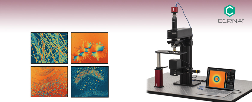
- Stress- and Strain-Induced Birefringence Imaging
- Raw Measurement Mode with Multiple Input Polarizations
- Measurements of Retardance and Azimuth (Fast Axis Orientation)
- Custom Operating Wavelengths Available from 488 to 780 nm
CM501
Cerna Birefringence Imaging Microscope with Manual Objective Arm
The optical table, sample holder,
and laptop are sold separately.
Sample Measurement Results Using the CM50x Software

Please Wait
Click to Enlarge
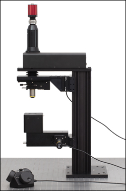
Side View of CM502 Microscope
| CM50x Configuration Comparisona | ||
|---|---|---|
| Item # | CM502 | CM501 |
| Included Motion Controller | MCM301 and MCMK3 | N/A |
| Included Objective Arm | ||
| Item # | PLSZ and PLSZ1 | ZFM1020b |
| Type | Motorized | Manual |
| Travel Range | 1" (25.4 mm) | |
| Resolution | Bidirectional Repeatability: 5 μm Min. Incremental Movement: 424 nm |
~ 2 mm / 30° |
| Recommended Objectivesc | N4X-PF, N10X-PF (Included), or N20X-PF | N4X-PF or N10X-PF (Included) |
Features
- Measures Sample Retardance Up to a Half-Wave at 633 nm (Up to 316 nm Retardance) and Azimuths (Fast Axis Orientation) Up to ±90°
- Spatial Resolution of 1.055 μm with Included 10X, 0.3 NA Objective
- Additional Verified Accurate Objectives Sold Below
- Built-In 633 nm Light Source
- Two Configurations Available
- Motorized Objective Arm (Microscope Item # CM502)
- Manual Objective Arm (Microscope Item # CM501)
- Custom Operating Wavelengths Available from 488 to 780 nm by Contacting Tech Support
Applications
- Stress-Induced Birefringence Imaging
- Birefringence Sensitive Tissue Analysis
- Dye-Free, Label-Free Imaging
- Structural Imaging
- Pathologic Diagnosis
- Material Research
- Quality Inspection
Thorlabs’ Cerna® Birefringence Imaging Microscopes are complete systems for measuring the retardance and azimuth of birefringent materials. With retardance measurements as low as ±1 nm, azimuth measurements as small as ±1°, spatial resolution of 1.055 μm with the included objective, and the flexible Cerna platform, these microscopes are a versatile solution for birefringence imaging. The CM50x microscopes are designed for use in academic research, medical diagnostics, industrial manufacturing, and product quality assurance. Since the operation is based on a liquid crystal device, there is no internal mechanical movement, leading to very stable, vibration-free operation. Please see the Technique tab above for details on operation and examples of application data taken with these microscopes.
The illumination wavelength of the systems offered below is 633 nm. This wavelength can be customized from 488 nm to 780 nm by contacting Tech Support. The system includes a standard objective with 10X magnification and measures retardance up to a half-wave at 633 nm (up to 316 nm retardance) and azimuths up to ±90°. The full specifications of these microscopes are outlined in the Specs tab.
The microscope body is built on the flexible Cerna platform with 95 mm dovetail for easy integration with the wide range of compatible sample holders or custom modules that use our Cerna body attachments to integrate components from our large catalog of optomechanics. The CSN1202 Nosepiece incorporated into the CM50x microscopes can also hold two objectives. Please refer to the Microscope Add-Ons tab above for recommendations on sample holders and objectives whose accuracy has been verified for these birefringence measurements.
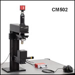
The CM50x microscope consists of a main microscope body, an LED illumination module, 10X Nikon objective, scientific grade CMOS camera, and either a motorized (Microscope Item # CM502) or manual (Microscope Item # CM501) focusing module. See the table to the right for a comparison the two configurations. The Shipping List tab above provides details on what comes with each configuration.
A Windows®-based software package is included with the birefringence imaging microscope that contains every feature needed for system control and data acquisition. To view additional information about this system's software features and sample measurement results, please refer to the Software tab above.
These systems can be installed by the user and detailed instructions are provided in the CM50x manual. An overview of the assembly steps is shown in the Assembly tab above, and the Connections tab highlights all system connections. An optional installation service is available for customers at additional charge. Please contact Tech Support.
For applications requiring a larger field of view, our LCC7201C Birefringence Imaging System offers the same retardance and azimuth range and accuracy, but over a Ø20 mm field of view, and at a lower spatial resolution of 9.77 μm.
CM50x Microscope Specifications
| General Specifications | |||
|---|---|---|---|
| Item # | CM502 | CM501 | |
| Light Source Wavelengtha | 632.8 nm ± 1 nmb | ||
| Microscope | Cerna® Series Microscope | ||
| Measurement Range | Retardance | Standard Retardance Range: 0 nm to 316 nm Low Retardance Range: 0 nm to 100 nm |
|
| Azimuth | ±90° | ||
| Measurement Accuracy | Retardance | Standard Retardance Range: ±10 nm Low Retardance Range: ±1 nm |
|
| Azimuth | Standard Retardance Range: ±3° Low Retardance Range: ±1° |
||
| Measurement Rate | <20 s (Based on Default Camera Settings) | ||
| Field of Viewc | 0.84 mm x 0.71 mm | ||
| Spatial Resolutionc | 1.055 μm | ||
| Interfaces | USB 2.0 and USB 3.0 | ||
| Imager Resolution | 2448 x 2048 Pixels (H x V) | ||
| Dimensions (D x W x H) | 469.6 mm x 354.1 mm x 836.3 mm (18.5" x 13.9" x 32.9") |
||
| Weight | 22.4 kg (49.4 lbs) | 21.9 kg (48.3 lbs) | |
| Operating Temperature | 0 °C to 40 °C | ||
| Storage Temperature | -15 °C to 65 °C | ||
| Scientific Camera Specificationsa | |
|---|---|
| Item # | CS505MU |
| Sensor Type | Monochrome CMOS |
| Number of Active Pixels | 2448 x 2048 (H x V) |
| Pixel Size | 3.45 μm x 3.45 μm |
| Imaging Area | 8.4456 mm x 7.0656 mm (H x V) |
| Host PC Interface | USB 3.0 |
| Vertical Digital Binninga | Continuous Integer Values from 1 to 16 |
| Horizontal Digital Binninga | Continuous Integer Values from 1 to 16 |
| Exposure Time | 0.021 ms to 7330 ms in ~0.007 ms Increments |
| Region of Interest (ROI) | Frame Rate |
| Full Sensor (2448 x 2048) | 53.2 fps |
| Half Sensor (1224 x 1024) | 133.7 fps |
| ~1/10th Sensor (260 x 208) | 563.2 fps |
| Min ROI (260 x 4) | 947.3 fps |
| Camera Port Specificationsa | |
|---|---|
| Item # | WFA4100 |
| Magnification | 1X |
| Dovetail | Male D1N |
| Tube Lens Focal Length | 200 mm |
| Objective Specificationsa | |
|---|---|
| Item # | N10X-PF |
| Magnification | 10X |
| Numerical Aperture (NA) | 0.3 |
| Working Distance (WD) | 16 mm |
| Parfocal Length | 60 mm |
| Design Tube Lens Focal Length | 200 mm |
| Coverslip Correction | 0.17 mm |
| Barrel Diameter | 30.0 mm |
| Length | 48.7 mm |
| Threading | M25 x 0.75 |
CM502 Motorized Arm Specifications
| MCM301 Controller Specifications | |
|---|---|
| Motor Output |
|
| Motor Drive Voltage |
24 V |
| Motor Drive Current | 7.0 A (Peak) 3.0 A (RMS) |
| Motor Drive Type | 12-Bit PWM Control |
| Control Algorithm | Open/Closed-Loop Microstepping |
| Stepping | 128 Microsteps per Full Step |
| Position Feedback | Quadrature Encoder (QEP) Input 5 V |
| Encoder Feedback Bandwidth | 1 MHz |
| Position Counter | 32-Bit |
| Operating Modes | Position and Velocity |
| Velocity Profile |
Trapezoid |
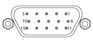
| Motor Drive Connector |
|
| Mechanical Specifications | 15 Position D-Type, Female Pin Connector |
| Motor Drive Outputs | Phase A and B |
| Quadrature Encoder (QEP) Input |
Single Ended |
| Limit Switch Inputs | Forward, Reverse (+ Common Return) |
| Encoder Supply | 5 V |
| Input Power Requirements | |
| Voltage | 24 VDC |
| Current | 6.67 A |
| General | |
| Computer Connection |
USB 2.0 |
| Housing Dimensions (W x D x H) |
5.91" x 4.52" x 1.91" (150.0 mm x 114.8 mm x 48.5 mm) |
| Compatible Motor Specifications | |
|---|---|
| Motor Type | 2-Phase Bi-Polar Stepper |
| Rated Phase Current | Up to 7 A Peak |
| Coil Resistance (Nominal) | 5 to 20 Ω |
| Position Control | Open or Closed Loop |
| PLSZ Motorized Translation Stage Specificationsa | |
|---|---|
| Travel Range | 1" (25.4 mm) |
| Bidirectional Repeatability | 5 µm |
| Backlash | 10 µm |
| Minimum Achievable Incremental Movement |
424 nm |
| Minimum Achievable Repeatable Movement |
1.06 μm |
| Velocity (Max) | 7 mm/s |
| Acceleration (Max) | 11 mm/s2 |
| Cable Length | 6' (1.8 m) |
| Pin Diagram | Click to View |
| Load Capacityb | Recommended: ≤5 lbs (2.3 kg) Maximum: 8 lbs (3.6 kg) |
| Stepper Motor Specifications | |
| Thread Screw Pitch | 0.3 mm |
| Step Angle | 1.8° |
| Limit Switches | Hall Effect Sensors |
| Phase Current | 0.49 A |
| Phase Resistance | 5.1 Ω |
| Insulation Resistance | 20 MΩ |
Click to Enlarge
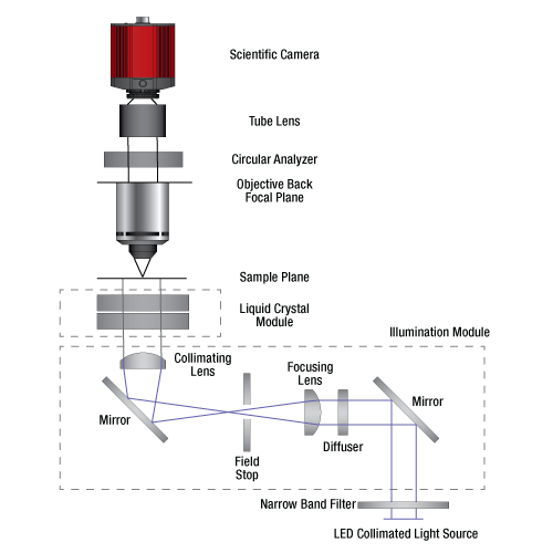
Optical Schematic of CM50x Birefringent Microscope
Birefringence Imaging
Polarized Light Microscopy
Polarized Light Microscopy provides high contrast images of birefringent materials and can be used for both qualitative and quantitative measurements of the retardance and azimuth of these materials. Standard polarized light microscopy requires two rotatable, crossed polarizers, a white light source, and an adjustable phase compensator. The first polarizer sets the polarization of light entering the sample and the second polarizer acts as an analyzer. Measurements of the retardance and the azimuth are accomplished by rotating the sample stage, adjusting the phase compensator, and recording the interference color. The quantitative retardance of the sample can be determined using a Michel-Levy color chart, and this path length difference can be converted to an index of refraction difference if the thickness of the sample is known. Conversely, if the index difference is known, this measurement can be used to determine thickness. Polarized light microscopy relies on multiple steps and can be time-consuming due to the need for a color camera, sample rotation, and phase compensator adjustment.
CM50x Microscope Advantages and Operation
The CM50x Cerna® Birefringence Imaging Microscopes use polarimetry to provide quick and easy measurements of retardance and fast axis orientation of birefringent transparent materials without the need for sample rotation or a color camera. These measurements support research in fields such as industrial manufacturing, biology, and medicine. The microscope measures multiple intensity images recorded with various polarization states, which are precisely controlled by a liquid crystal module. Since there is no internal mechanical movement, these microscopes provide very stable, vibration-free operation.
A diagram of the system operation for the CM50x microscopes is shown at the right. An M625L4 Mounted LED in combination with a collimation lens and a previous-generation FL632.8-1 Filter provide a 633 nm collimated light source that is steered into the liquid crystal module by a WFA1000 Trans-Illumination Module. The liquid crystal module can set a number of different linear and circular input polarizations. The sample under test is placed at the focal plane of an included N10X-PF 10X objective (Nikon Plan Fluorite, 0.3 NA). Additional objectives with higher or lower NAs that have been verified to produce accurate birefringence measurements when used with the CM50x systems are also available. Please see recommendations in the Microscope Add-Ons tab above. A circular analyzer is set at the back focal plane of the objective to filter the transmitted light. A CS505MU Monochrome Scientific Camera records the intensity images for each sequential input state of polarization.
For details on system set up and general operation, please see the CM50x manual.
Applications
The CM50x Microscopes have applications in a variety of research and manufacturing fields. With the same retardance and azimuth range and accuracy as our LCC7201C Birefringence Imaging System, but higher spatial resolution of 1.055 μm with the included 10X objective compared to the 9.77 μm resolution of the LCC7201C system, these microscopes are a versatile solution to birefringence imaging.
Below, we show measurements of laser-induced birefringence in a polymer wave plate, stress-induced birefringence in an optical fiber, and several examples of birefringence in biological tissue. Click the tabs below for details.
Laser-Induced Birefringence in a Polymer Wave Plate
Laser-Induced Birefringence Change in a Polymer Wave Plate
When a quartz or liquid crystal polymer wave plate is integrated into a system for a given application, the laser induced birefringence change, i.e., retardance and fast axis orientation (azimuth), can be critical. Since even a very slight change can create problems in practical applications, the verification of such changes is essential.
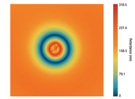
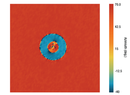
The images below show retardance and azimuth measurements over an area of approximately 200 µm x 200 µm for a WPH10E-830 Liquid Crystal Polymer Zero-Order Wave Plate that had been damaged during laser-induced damage threshold (LIDT) testing. Because the damaged area, visible in the center of each image, has large changes in retardance, these measurements were taken using the Standard Retardance Range mode in the included software. When the retardance changes in the damaged region are small but still significant to performance, they can be difficult to measure with a standard polarized light microscope. Our CM50x microscopes are sensitive to retardance and azimuth changes as small as ±1 nm and ±1° when using the Low Retardance Range measurement mode, allowing for more subtle changes in performance to be identified during quality inspection. See the Software tab for more details on available measurement modes.
Click to Enlarge
2D Retardance View of a Liquid Crystal Polymer Waveplate
Click to Enlarge
2D Azimuth View of a Liquid Crystal Polymer Waveplate
Birefringence in Biological Tissue
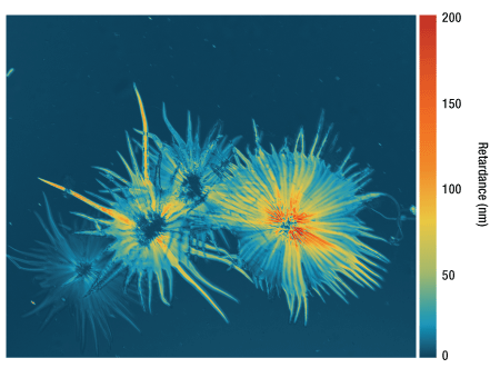
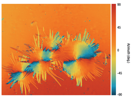
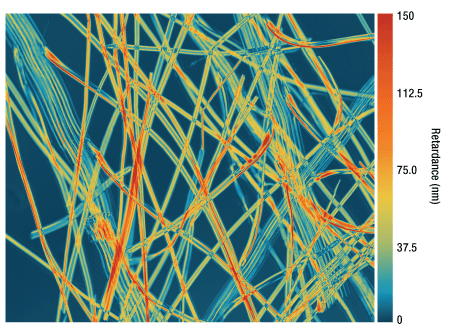
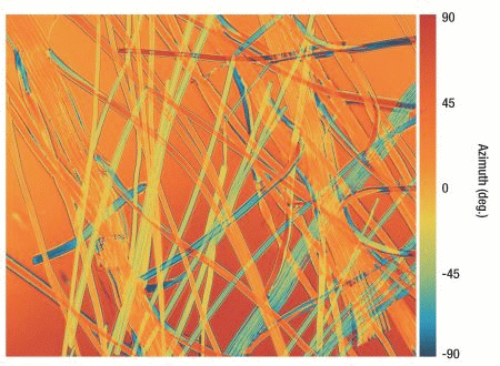
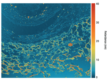
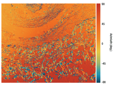
The Cerna Birefringence Imaging Microscope is a powerful tool to reveal submicroscopic organization in biological materials. It offers rapid measurements to study and understand biological structures, such as striated muscle, nerve myelin, mitotic spindle, dermal collagen, and stress fibers, without staining or labeling. Some example measurements, covering the full field of 0.84 mm x 0.71 mm, are shown below.
Berry Hair Whole Mount (w.m.) (Complete Organism)
Click to Enlarge
2D Retardance View of Berry Hair Whole Mount (w.m.)
Click to Enlarge
2D Azimuth View of Berry Hair Whole Mount (w.m.)
Dandelion Fuzz Whole Mount (w.m.) (Complete Organism)
Click to Enlarge
2D Retardance View of Dandelion Fuzz Whole Mount (w.m.)
Click to Enlarge
2D Azimuth View of Dandelion Fuzz Whole Mount (w.m.)
Leaf of Nerium Indicum T.S.

Click to Enlarge
2D Retardance View of Leaf of Nerium Indicum T.S.

Click to Enlarge
2D Azimuth View of Leaf of Nerium Indicum T.S.
Tomato Flesh Whole Mount (w.m.) (Complete Organism)
Click to Enlarge
2D Retardance View of Tomato Flesh Whole Mount (w.m.)
Click to Enlarge
2D Azimuth View of Tomato Flesh Whole Mount (w.m.)
Human Hair (w.m.) (Complete Organism)

Click to Enlarge
2D Retardance View of Human Hair (w.m.)

Click to Enlarge
2D Azimuth View of Human Hair (w.m.)
Click to Enlarge
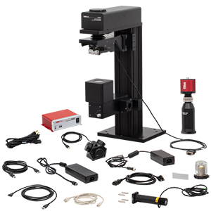
CM502 Components
CM502 Cerna® Birefringence Imaging Microscope, Motorized Objective Arm
Item # CM502 consists of:
- Main CM502 Microscope Body
- Camera Assembly
- LED Assembly
- 10X Objective (Item # N10X-PF)
- Birefringent 1951 USAF Test Target (Item # R3L1S1B)
- 12 VDC Power Supply (Item # DS12)
- Region-Specific Power Cord
- USB Drive with Software and Manual (Not Shown)
- USB 2.0 Type-A to Type-B Cable, 2 m
- USB 3.0 A to Micro B Cable, 3 m (Appearance May Vary from Photo)*
- Control Cable, 2 m
- Protective Tape for Shipping and Storage (Not Shown)
- CCHK/M Metric Hex Key Set (Not Shown)
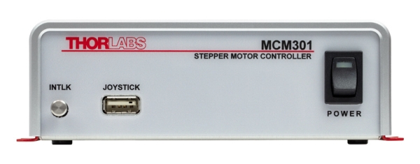
- Three-Channel Controller for Motorized Rigid Stands and PLS Series Stages (Item # MCM301) which includes:
- Controller Box
- Power Supply, with Region-Specific Power Cord
- USB Cable (A to B)
- 3-Knob USB HID Joystick (Item # MCMK3)
*The microscope performance specifications provided are guaranteed only with the provided USB 3.0 cable.
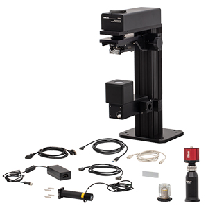
Click to Enlarge
CM501 Components
CM501 Cerna Birefringence Imaging Microscope, Manual Objective Arm
Item # CM501 consists of:
- Main CM501 Microscope Body
- Camera Assembly
- LED Assembly
- 10X Objective (Item # N10X-PF)
- Birefringent 1951 USAF Test Target (Item # R3L1S1B)
- 12 VDC Power Supply (Item # DS12)
- Region-Specific Power Cord
- USB Drive with Software and Manual (Not Shown)
- USB 2.0 Type-A to Type-B Cable, 2 m
- USB 3.0 A to Micro B Cable, 3 m (Appearance May Vary from Photo)*
- Control Cable, 2 m
- Protective Tape for Shipping and Storage (Not Shown)
- CCHK/M Metric Hex Key Set (Not Shown)
*The microscope performance specifications provided are guaranteed only with the provided USB 3.0 cable.
Application-Optimized Cerna Microscopes
Developed in collaboration with our colleagues in the field, the Cerna microscopy platform is uniquely modular and flexible, making it adaptable to a wide range of demanding experimental requirements. If you would like to work with our application specialists, engineers, and sales team to design your own microscope, please email ImagingSales@thorlabs.com.
Selected Accessories
In order to image with the CM50x Birefringence Imaging Microscopes, it is necessary to add a sample holder. To that end, we have ensured that Cerna® microscopes are compatible with a wide range of accessories. The information below compares some suggested Cerna-compatible components. For a comprehensive list of sample holders, please see our Sample Holders for DIY Cerna Systems.
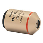
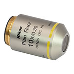
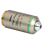
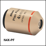
The CSN1202 Nosepiece incorporated into the CM50x microscopes can hold two objectives. The systems come with an N10X-PF objective. Additional verified compatible objectives are listed below.
Content
Verified Objectives
| Item # | N4X-PF | N10X-PF | N20X-PF |
|---|---|---|---|
| Photo (Click to Enlarge) |
 |
 |
 |
| Objective Class | Plan Fluorite | ||
| Magnificationa | 4X | 10X | 20X |
| Numerical Aperture (NA) | 0.13 | 0.3 | 0.50 |
| Working Distance (WD) | 17.2 mm | 16 mm | 2.1 mm |
| Parfocal Length | 60 mm | ||
| Threading | M25 x 0.75 | ||
- CM50x Imaging Systems Directly Accept M25 x 0.75-Threaded Objectives (Nikon)
- Unverified Objectives Not Recommended
The CSN1202 nosepiece can hold two objectives with M25 x 0.75 threads, commonly used by Nikon objectives. One N10X-PF 10X, 0.3 NA objective is included with each CM50x microscope. Since high-NA optics contribute residual birefringence and might impact the system accuracy, we verified three widefield Nikon objectives, shown in the table to the right, to ensure that the system accuracy can still be guaranteed while switching the objectives. Unverified objectives may result in loss of measurement accuracy and are not recommended.
Please note that objectives with a magnification greater than 10X are not recommended for use with the CM501 Microscope with Manual Objective Arm, as the focusing resolution is not sufficient for these higher NA objectives.
Please Note: Unverified objectives may lead to inaccurate birefringence measurements due to residual birefringence of the objectives. For applications requiring objectives outside those recommended here, please contact Tech Support to discuss your imaging needs.
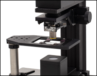
Click for Details
CM501 Microscope with
MLS203P2 Slide Holder,
MPRM(/M) Rectangular Insert Holder, MPP20 Post, and LPH200 Post Holder
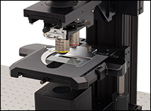
Click to Enlarge
CM502 Microscope with CSA1051 Adapter Arm, CSS2001 Manual XY Stage, and CS2000 Slide Holder
Sample Holders
- Rigid Stands Hold Samples Underneath and Around the Objective
- Designed for Slides, Petri Dishes, Well Plates, Recording Chambers, Micromanipulators, and Custom Inserts
- Motorized and Manual Translation Stages with X and Y Travel Available
- Fixed Arms to Incorporate Fast XY Stage, Manual XY Stage, Lens Tubes, and/or Cage Systems to be Placed Directly into Optical Path
- CSA1000: For Our MLS203-1 Fast XY Scanning Stage
- CSA1051: For CSS2001 Olympus Manual Stage
- CSA1001: For Ø1" Lens Tubes and 30 mm Cage Systems
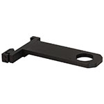
- CSA1002: For Ø2" Lens Tubes and 60 mm Cage Systems
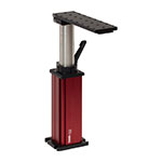
Thorlabs offers highly configurable solutions for mounting your sample beneath the objective of the Cerna microscope. Rigid stands are available with multiple platform styles that can accept slides, petri dishes, recording chambers, and custom inserts. The included collar makes them lockable at a height and angle chosen by the user. An example rigid stand is shown at the right integrated with the CM501 Microscope. We also offer translation stages for these rigid stands that provide motorized horizontal translation of the sample.
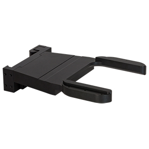
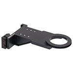
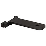
Our fixed arms attach directly to the dovetail that spans the height of the microscope body, allowing them to be positioned anywhere along the body height, putting the sample directly into the microscope's optical path, and taking advantage of the existing footprint of the scope. For a pre-configured motorized sample holder solution, use the CSA1000 Fixed Arm with the MLS203-1 Fast XY Scanning Stage (shown in the left-most image above). This stage is compatible with our MZS500-E Piezo-Driven Insert, which adds high-resolution Z-axis adjustments. The CSA1051 Adapter Arm, paired with the CSS2001 Olympus Manual Stage and CSS2000 Olympus Slide Holder, provides a manual XY solution, shown in the center image above. Alternatively, the CSA1001 and CSA1002 Fixed Arms are compatible with Thorlabs' extensive selection of optomechanical components, allowing custom sample holder configurations to be integrated with this microscope.
Several compatible options are outlined in the tables below. For a comprehensive list of options, please see our Sample Holders for DIY Cerna Systems.
Rigid Stands
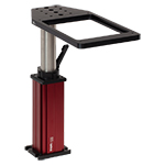 Click to Enlarge MPRM(/M) Rectangular Insert Holder, MPP20 Post, and LPH200 Post Holder
|
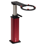 Click to Enlarge MPRC(/M) Recording Chamber Holder, MPP25 Post, and
|
 Click to Enlarge MP20(/M) Rigid Stand with Platform
|
Fixed Arms
 Click to Enlarge CSA1000 Fixed Arm
|
 Click to Enlarge CSA1051 Adapter Arm
|
 Click to Enlarge CSA1001 Fixed Arm
|
 Click to Enlarge CSA1002 Fixed Arm
|
These microscope systems can be installed by the user and detailed instructions are provided in each manual. An optional installation service is available for these systems at additional charge. Please contact Tech Support for details.
Click to Enlarge
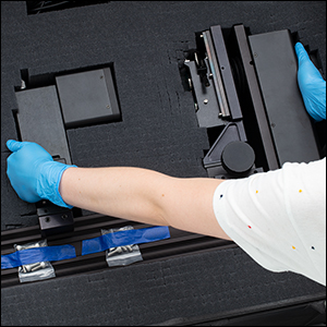
Step 1: Use both hands to transfer the main unit to the optical table using the holding points shown above. Always wear gloves when handling, setting up, and working with the system.
Click to Enlarge
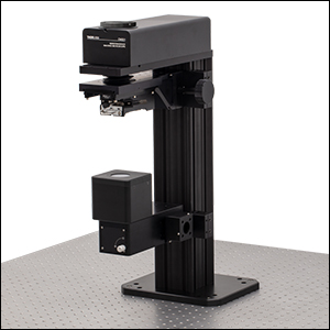
Step 2: Mount the main unit onto the optical table using at least four screws, i.e., at least one screw at each corner.
Click to Enlarge
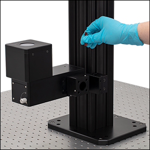
Step 3: Unscrew the two illumination module dust cover locking screws and remove the cover.
Click to Enlarge
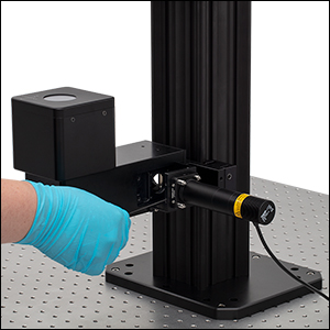
Step 4: Connect the LED assembly using the four cage plate rods. Tighten the four locking screws on the illumination module to secure the cage rods to the main microscope body.
Click to Enlarge
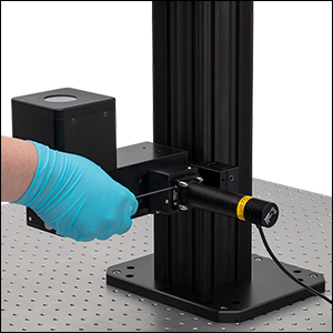
Step 5: Replace the illumination module dust cover and tighten the four locking screws in the CP33/M Cage Plate to secure the cage rods to the cage plate.
Click to Enlarge
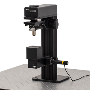
Step 6: Remove the green protective tape on the objective holder and install the N10X-PF Objective into the CSN1202 Nosepiece.
Click to Enlarge
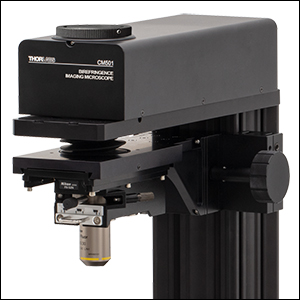
Step 7: Loosen the locking screw on the front of the microscope, above the product label, with a 2 mm hex key and remove the dust cover on the camera port.
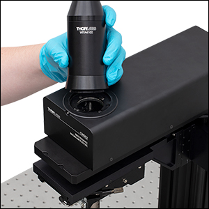
Click to Enlarge
Step 8: Put the camera assembly on the camera port and secure the camera assembly with the locking screw.
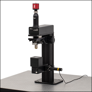
Click to Enlarge
Step 9: Final CM501 Microscope Assembly
CM50x Microscope Connections
Click to Enlarge
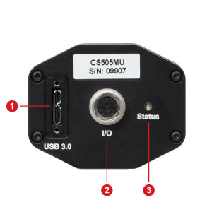
CM50x Camera Connections
Click to Enlarge
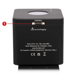
CM50x Control Box Connection
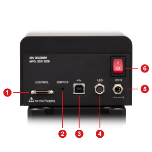
Click to Enlarge
CM50x Main Body Connections
| Camera Connections | |
|---|---|
| Callout | Description |
| 1 | USB 3.0 Micro B Connector (to Computer)a |
| 2 | 12 Pin Hirose Female Connector (Not Used) |
| 3 | Status LED |
| Control Box Connection | |
|---|---|
| Callout | Description |
| 1 | Control Cable Connection (to Main Body) |
| Microscope Main Body Connections | |
|---|---|
| Callout | Description |
| 1 | Control Cable Connection (to Control Box) |
| 2 | Service Switch (for Technical Support Only) |
| 3 | USB 2.0 Type B Connector (to Computer) |
| 4 | LED Connector |
| 5 | Power Supply Connector |
| 6 | Power Switch |
CM502 Motorized Arm Controller Connections
MCM301 |
||||||||||||||||||||||||||||||||||||
Adapter Cable Connector for Motor Drive
|
Computer Connection
|
|||||||||||||||||||||||||||||||||||
|
||||||||||||||||||||||||||||||||||||
Software
Version 2.2.11
Click the button below to visit the Cerna Birefringence Imaging Microscope software page.
The Cerna® Birefringence Imaging Microscopes include a Windows®-based software package with every feature needed for system control and data acquisition. Please click the Software button to the right to download the latest software for this system.
Features
- Standard and Low Noise Modes for Retardance and Azimuth Measurements
- Raw Sample Mode for Intensity Measurement
- Selectable Rectangular, Circular, or Polygon Region of Interest (ROI)
- Adjustable Dynamic Camera Settings (Gain, Exposure Time, Black Levels)
- Overexposure Detection
- Auto Adjustment of Light Source Level
- 1D, 2D, and 3D Measurement Result Displays
- Data Output in Binary, CSV, and Image (PNG and TIFF) Formats
- SDK for C++, LabVIEW™, and Python Programming Environments
The software includes three modes: Standard Mode and Low-Noise Mode, which are used to measure a sample's retardance and azimuth, and Raw Sample Mode, which is used to measure intensity with different input polarizations. Standard and Raw Sample Modes provide a higher measurement rate with a lower signal-to-noise ratio, while Low Noise Mode provides a lower measurement rate with a higher signal-to-noise ratio. An exposure time of 300 ms is set as the default, which allows a measurement to be finished within 20 seconds in Standard Mode and 4 minutes in Low Noise Mode.
The standard and low-noise modes provide two ranges of measurement accuracy: Standard Retardance Range and Low Retardance Range. Standard Retardance provides a measurement accuracy of ±10 nm for retardances in the 0 nm to 316 nm range and ±3° for azimuths over the entire measurement range. Low Retardance Range will improve the measurement accuracy to ±1 nm for retardances in the 0 nm to 100 nm range and ±1° for azimuths over the entire measurement range. The minimum exposure time is 0.021 ms, and the maximum exposure time is 7330 ms.
Below are screenshots from the included user interface, showing the different measurement display modes available. The Preview, 1D, 2D, and 3D views are all of a liquid crystal polymer zero-order half wave plate (Item # WPH10E-830).
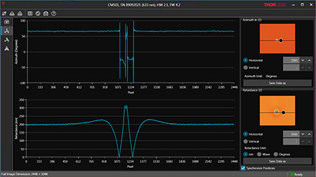
Click to Enlarge
Azimuth and Retardance 1D View

Click to Enlarge
Camera Preview
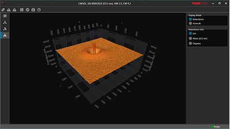
Click to Enlarge
Retardance 3D View
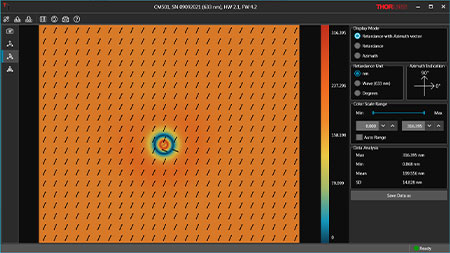
Click to Enlarge
Retardance with Azimuth Vector 2D View
Click to Enlarge
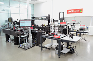
Figure 39A China Demo Room
Try Our Microscopes In Person or Virtually
Thorlabs' sales engineers and field service staff are based out of nine offices across four continents. We look forward to helping you determine the best imaging system to meet your specific experimental needs. Our customers are attempting to solve biology's most important problems; these endeavors require matching systems that drive industry standards for ease of use, reliability, and raw capability.
Thorlabs' worldwide network allows us to operate demo rooms in a number of locations where you can see our systems in action. We welcome the opportunity to work with you in person or virtually. A demo can be scheduled at any of our showrooms or virtually by contacting ImagingSales@thorlabs.com.
Customer Support Sites
(Click Each Location for More Details)
Newton, New Jersey, USA
Thorlabs Headquarters
43 Sparta Avenue
Newton, NJ 07860
Customer Support
- Phone: (973) 300-3000
- E-mail: techsupport@thorlabs.com
Ely, United Kingdom
Thorlabs Ltd.
1 Saint Thomas Place, Ely
Ely CB7 4EX
Customer Support
- Phone: +44 (0)1353-654440
- E-mail: techsupport.uk@thorlabs.com
Bergkirchen, Germany
Thorlabs GmbH
Münchner Weg 1
85232 Bergkirchen
Customer Support
- Phone: +49 (0) 8131-5956-0
- E-mail: europe@thorlabs.com
Puteaux, France
Thorlabs SAS
76 Route de la Demi Lune
92800 Puteaux
Customer Support
- Phone: +33 (0) 970 440 844
- E-mail: techsupport.fr@thorlabs.com
São Carlos, SP, Brazil
Thorlabs Vendas de Fotônicos Ltda.
Rua Rosalino Bellini, 175
Jardim Santa Paula
São Carlos, SP, 13564-050
Customer Support
- Phone: +55-16-3413 7062
- E-mail: brasil@thorlabs.com
Demo Rooms and Customer Support Sites
(Click Each Location for More Details)
Sterling, Virginia, USA
Thorlabs Imaging Systems HQ
108 Powers Court
Sterling, VA 20166
Customer Support
- Phone: (703) 651-1700
- E-mail: ImagingTechSupport@thorlabs.com
Demo Rooms
- Bergamo® Series Multiphoton Microscopes
- Veneto® Inverted Microscopes
- Four-Channel Cerna®-Based Confocal Microscopes
- Cerna Birefringence Imaging Microscopes
- Multiphoton Mesoscope
- OCT Systems: Telesto® and Ganymede™
Lübeck, Germany
Thorlabs GmbH
Maria-Goeppert-Straße 9
23562 Lübeck
Customer Support
- Phone: +49 (0) 8131-5956-40840
- Email: oct@thorlabs.com
Demo Rooms
- Ganymede™ Series SD-OCT Systems
- Telesto® Series SD-OCT Systems
- Telesto® Series PS-OCT Systems
- Atria® Series SS-OCT Systems
- Vega™ Series SS-OCT Systems
Nerima-ku, Tokyo, Japan
Thorlabs Japan, Inc.
3-6-3 Kitamachi
Nerima-ku, Tokyo 179-0081
Customer Support
- Phone: +81-3-6915-7701
- Email: sales@thorlabs.jp
Demo Rooms
- Four-Channel Cerna®-Based Confocal Systems
- Cerna® Modular Brightfield Microscopes
- OCT Systems: Ganymede™
Shanghai, China
Thorlabs China
Room A101, No. 100, Lane 2891, South Qilianshan Road
Shanghai 200331
Customer Support
- Phone: +86 (0)21-60561122
- Email: techsupport-cn@thorlabs.com
Demo Rooms
- Bergamo® Series Multiphoton Microscopes
- Cerna Birefringence Imaging Microscopes
- OCT Systems: Telesto® and Ganymede™
| Posted Comments: | |
| No Comments Posted |

Click to Enlarge
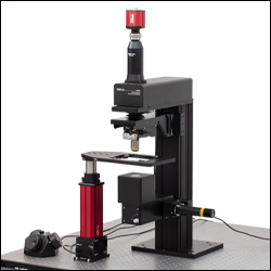
The CM502 microscope is shown here with a rigid stand equipped with a sample holder and a PLSXY motorized XY translation stage.
- Appropriate for Full Range of Verified Objectives (See Microscope Add-Ons Tab)
- 10X Objective Included
- 4X and 20X Verified Objectives Available Separately Below
- Provides Motorized Focusing Adjustment over 1" Travel Range
- Operated by Included MCM301 Three-Channel Controller and MCMK3 Joystick
The CM502 Birefringence Imaging Microscope with Motorized Objective Arm incorporates our PLSZ Motorized Focusing Module to provide 1" of fine, variable-speed travel along the Z axis for focusing the system. Some key specifications for this module are shown in the table below. The focusing module requires the MCM301 Three-Channel Controller, which is included with the CM502 microscope. The fine Z-axis control allows this microscope to be used with higher resolution objectives (not included). Since high NA optics contribute residual birefringence and might impact the system accuracy, we only recommend objectives whose accuracy we have verified. For a list of verified objectives, please see the Microscope Add-Ons tab above.
| PLSZ Motorized Translation Stage Specifications | |
|---|---|
| Travel Range | 1" (25.4 mm) |
| Bidirectional Repeatability | 5 µm |
| Backlash | 10 µm |
| Minimum Achievable Incremental Movement | 424 nm |
| Minimum Achievable Repeatable Movement | 1.06 µm |
| Velocity (Max) | 7 mm/s |
| Acceleration (Max) | 11 mm/s2 |
For additional motion control, our PLSX or PLSXY Translation Stage can be incorporated into the CM502 microscope with a rigid stand and sample holder (all items sold separately). The PLSX and PLSXY stages require the MCM301 Three-Channel Controller for operation. The Standard CM502 comes with a MCM301 Three-Channel Controller with two free ports available. Therefore it is not necessary to purchase an additional MCM301 controller if the motorized sample stage solution is chosen. The image at the right shows the CM502 system used with a PLSXY motorized XY translation stage, a rigid stand, and an MLS203P2 Slide Holder. The rigid stand is constructed with an MPRM(/M) Insert Holder mounted on an MPP20 Post, supported by the LPH200 Rigid Stand Post Holder.
More examples of recommended sample holders are listed in the Microscope Add-Ons tab above. For a comprehensive list of options, please see our Sample Holders for DIY Cerna Systems.


Click to Enlarge
CM501 Microscope with Manual XY Stage and Sample Holder
- Coarse Focusing Adjustment Appropriate for Lower Resolution Imaging
- Appropriate for Use with 10X Objective (Included) or 4X Verified Objective (Sold Separately Below)
- Provides Manual Focusing Adjustment over 1" Travel Range
The CM501 Birefringence Imaging Microscope with Manual Objective Arm incorporates our ZFM1020 Manual Condenser Focusing Module to provide 1" of coarse adjustment along the Z axis for focusing the objective. This focusing module is controlled manually with approximately 2 mm of Z movement per 30° of rotation of the manual knob. For full specifications on the ZFM1020 Manual Condenser Focusing Module, please see the full web presentation. The CM501 microscope is appropriate for wider field of view imaging with lower resolution. We recommend this microscope for use with the included 10X objective as well as lower magnifications, such as the N4X-PF Imaging Objective.
| Manual Focusing Module Specificationsa | |
|---|---|
| Travel Range | 1" (25.4 mm) |
| Distance per Degree Turn of Focus Knobb | ~2 mm / 30° |
A full microscope system requires a sample holder. An example configuration is shown at the right. The CM501 microscope is incorporated with an MLS203P2 Slide Holder, on an MPRM(/M) Insert Holder attached to an MPP20 Post. This post is supported by the LPH200 Rigid Stand which is in turn mounted on XR25P(/M) and XR25C(/M) Linear Translation Stages, for full manual XYZ control. A manually controlled system provides a cost-effective, full birefringence imaging system for lower resolution applications. The addition of a motorized sample stage in Z can also be used to make the CM501 microscope appropriate for higher resolution applications.
More examples of recommended sample holders and stages are listed in the Microscope Add-Ons tab above. For a comprehensive list of options, please see our Sample Holders for DIY Cerna Systems.


Click to Enlarge
CM502 Microscope with Additional 4X Objective and Manual XY Sample Stage
- Infinity-Corrected Plan Fluorite Design
- Verified for Use with CM50x Birefringence Imaging Microscopes
- M25 x 0.75 Threading
- Designed for a Tube Lens Focal Length of 200 mm
- 60 mm Parfocal Length
The Nikon Plan Fluorite Objectives sold on this page provide 4X or 20X magnification. They are designed to have high transmission in the UV to NIR wavelength range and to produce flat images across the field of view. Objectives here have been verified to provide accurate results when used with the CM50x microscopes. These multi-purpose objectives can also be utilized for brightfield microscopy, fluorescence microscopy, and polarization-sensitive observations. The N20X-PF objective is also good for both darkfield and DIC microscopy.
Each objective is designed for use with a tube lens focal length of 200 mm and is compatible with our DIY Cerna® Systems. They use M25 x 0.75 threading; to use these objectives with a different thread standard, please see our microscope objective thread adapters.
These objectives are designed for use from -18 °C (0 °F) to 60 °C (140 °F) and are not recommended for use at extreme temperatures.
| Item # | Wavelength Range | Ma | WD | EFL | NA | EPb | Resolutionc | PFL | Cover Glass Thickness |
Objective Threading |
|---|---|---|---|---|---|---|---|---|---|---|
| N4X-PF | UV to NIR | 4X | 17.2 mm | 50 mm | 0.13 | 13 mm | 2.6 µm | 60 mm | 0 - 0.17 mm | M25 x 0.75; 3.6 mm Depth |
| N20X-PF | 20X | 2.1 mm | 10 mm | 0.50 | 10 mm | 0.7 µm | 0.17 mm | M25 x 0.75; 5 mm Depth |
 Products Home



 Zoom
Zoom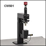
 Birefringence Imaging Microscopes