 Products Home
Nanosecond Pulsed Laser Systems
- Center Wavelength Options from 405 nm to 980 nm
- Fixed or Adjustable Pulse Widths
- Repetition Rates up to 10 MHz
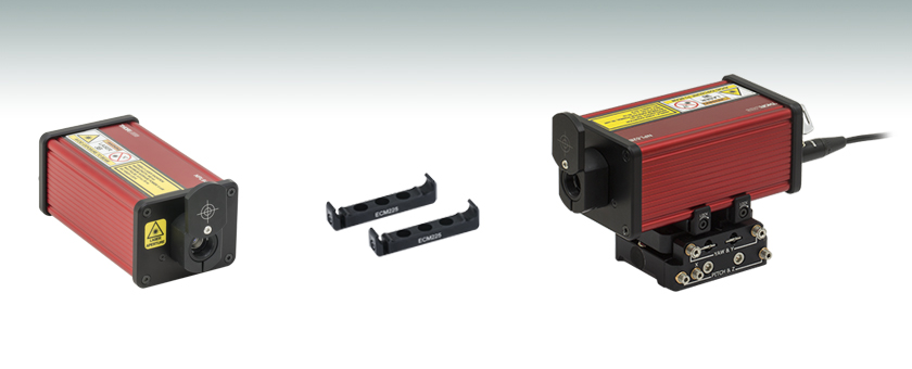
- Compact Laser System with Collimated Free Space Output
Application Idea
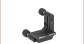
Adjust beam pointing angle tip and tilt when the laser (NPL52B shown) is mounted on the PY005 five-axis stage.
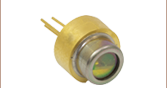
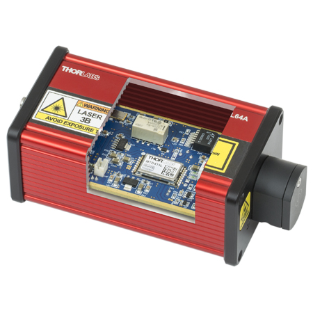
NPL52B
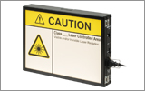
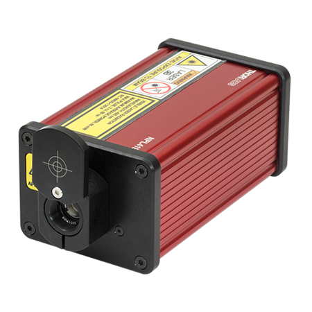
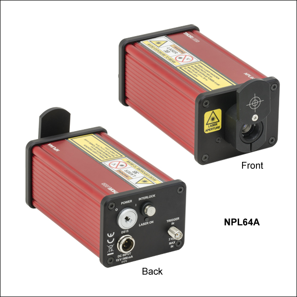
The drive electronics and temperature stabilization circuits for the laser diode are all integrated into the laser head.
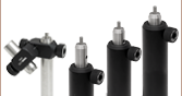
Two ECM225 mounting clamps are included with each NPL Series laser.


Please Wait
| Key Specificationsa | |||||||
|---|---|---|---|---|---|---|---|
| Item # | Center Wavelengthb |
Pulse Widtha |
Pulse Energy |
Peak Power |
Average Power |
Max Rep. Rate |
Internal Trigger |
| NPL64A | 640 nm | 10 ns | 0.12 nJ | 13 mW | 1.2 mW | 10 MHz | No |
| NPL41B | 405 nm | 6 to 38 ns | 1.5 nJ | 38 mW | 15 mW | 10 MHz | Yes |
| NPL45B | 450 nm | 5 to 39 ns | 3.0 nJ | 75 mW | 30 mW | ||
| NPL49B | 488 nm | 6 to 39 ns | 2.0 nJ | 50 mW | 20 mW | ||
| NPL52B | 520 nm | 5 to 39 ns | 1.2 nJ | 30 mW | 12 mW | ||
| NPL64B | 640 nm | 5 to 39 ns | 2.0 nJ | 50 mW | 20 mW | ||
| NPL79B | 785 nm | 6 to 39 ns | 3.5 nJ | 88 mW | 35 mW | ||
| NPL82B | 820 nm | 6 to 39 ns | 3.5 nJ | 88 mW | 35 mW | ||
| NPL91B | 905 nm | 6 to 39 ns | 3.5 nJ | 88 mW | 35 mW | ||
| NPL98B | 980 nm | 6 to 39 ns | 1.5 nJ | 38 mW | 15 mW | ||
| NPL41C | 405 nm | 6 to 129 ns | 128 nJ | 1000 mW | 6.4 mW | 50 kHz | No |
| NPL45C | 450 nm | 204 nJ | 1600 mW | 10.2 mW | |||
| NPL52C | 520 nm | 186 nJ | 1500 mW | 9.3 mW | |||
| NPL64C | 640 nm | 126 nJ | 1000 mW | 6.3 mW | |||
| NPL81C | 808 nm | 186 nJ | 1500 mW | 9.3 mW | |||
| NPL94C | 940 nm | 129 nJ | 1000 mW | 6.5 mW | |||
Features
- Center Wavelengths from 405 to 980 nm
- Drive and Temperature Stabilization Electronics Integrated into Laser Head
- Fixed and Adjustable Pulse Width Models (See Table to the Right)
- Models with Internal Triggering up to 10 MHz (Item #s Ending in B)
- High-Power Models up to 1600 mW Peak Pulse Power (Item #s Ending in C)
- Two ECM225 Clamps Included for Post Mounting the Laser Head
- Replacement Power Supply Available
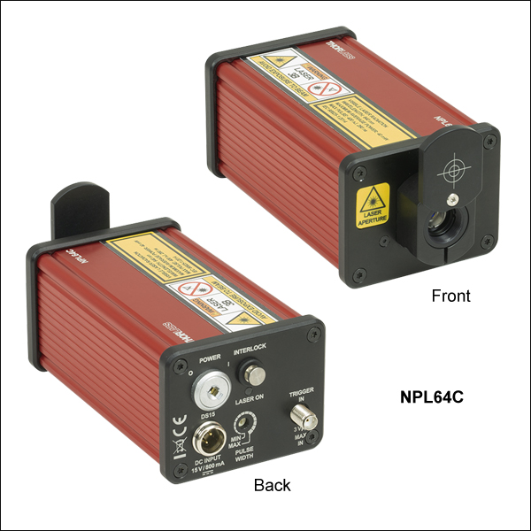
Thorlabs' Nanosecond Pulsed Laser Diode Systems are designed to provide a convenient, turnkey source of nanosecond pulse trains at repetition frequencies up to 10 MHz. These compact instruments consist of a laser head, an external +15 V power supply with location-specific plug, and two ECM225 mounting clamps. The drive electronics and temperature stabilization circuits for the laser diode are all integrated into the laser head, as are safety interlocks. A safety shutter can be rotated to cover the optical output port, as shown in the images below. The maximum peak pulse optical output powers vary from 13 mW to 1600 mW, depending on Item #, as specified in the table to the right.
Adjustable and Fixed Pulse Width Options
The NPL64A laser system provides fixed-width pulses with 10 ns typical durations in response to a user-supplied trigger signal input to the SMA connector on the back panel. Lasers with Item #s ending in B or C have user-adjustable pulse durations, as specified in the table to the right.
Triggering
All of these lasers support external triggering and require a trigger signal to generate laser pulses. External trigger signals have a maximum supported edge transition time of 1 ms. Lasers with Item #s ending in B also feature an internal trigger which is described below. The repetition rate can be anything from a single shot up to the max repetition rate specified in the table to the upper right.
Lasers with internal triggers (Item #s ending in B) also feature internal oscillators that generate 1, 5, or 10 MHz frequency trigger signals, enabling these systems to produce stable trains of nanosecond laser pulses without an external trigger. The Rep Rate selector on the back panel allows the user to easily choose the desired internal or external trigger setting. Depending on the Rep Rate selector setting, the SMA connector on the back panel outputs a signal synchronized with the internally triggered pulses or accepts the user supplied trigger signal. For additional information, please see the Specs tab and the Back Panels tab.
Optical Emission
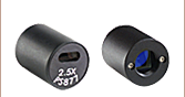
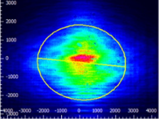
The optical output is a linearly polarized, free-space beam collimated by an integrated aspheric collimating lens, which is permanently fixed in a tube located behind the shutter. The lens position is factory set for a nominal divergence of about 1 mrad. The output beam is elliptical, as is typical of solid-state diode lasers that do not use anamorphic optical components to circularize the beam. If an application requires circularizing the beam, Thorlabs offers anamorphic elements, such as anamorphic prism pairs. Please see the Lab Facts tab above for more information on beam circularization techniques.
For fiber-coupled optical output options, we recommend choosing from our selection of coupling packages to accommodate the NPL series' larger beam diameter.
Output Power
The average optical output power of these laser systems is the product of the repetition rate, the pulse width, and the peak pulse power. The maximum average output power, which is specified in the table to the upper right, is factory-set for each unit while it operates at the maximum repetition rate and emits pulses of maximum width. By dividing this average power by the repetition rate and the pulse width, it is possible to estimate the peak pulse output power. However, there are unit-to-unit variations in the pulse width across a particular model. For Item #s ending in B or C, the peak output power may be up to 15% greater or 24% lower than the value given in the table to the upper right. Please note, as can be seen in the Typical Pulses plots below, that some short-duration pulses do not reach the maximum optical powers of longer-duration pulses. These pulses consequently have lower average output powers than longer-duration pulses.
Mounting the Laser Housing
The NPL series laser housings can be mounted to stages, bases, or posts using the two included ECM225 mounting clamps, each of which has three counterbores that accept 8-32 (M4) cap screws (not included). Using both clamps when mounting these lasers protects against misalignment in the event that the laser is bumped. An applied force can cause rotation around a single point of contact, but rotation is resisted when there are two or more points of contact.
Before attaching the clamps to the laser housing, each clamp must first be screwed to the stage, base, or post. After this is done, loosen the 5/64" (2.0 mm) locking screw in each clamp, insert the laser housing into the clamps, and then tighten the locking screws on both clamps until the laser housing is held securely. Compatible mounting fixtures with tip and tilt (pitch and yaw) adjustment capability, which can be helpful when the application requires tuning laser beam pointing angle, include the PY005(/M) Five-Axis Stage and the TTR001(/M) Tip, Tilt, and Rotation Stage. If desired, ECM175 mounting clamps, available below, can alternatively be used to mount the laser on its side.

Adam Knapp
Ultrafast Optoelectronics
General Manager
We Design, Develop, and Manufacture
Equipment Up to 110 GHz
Questions?
Demo Unit Requests?
Product Suggestions?
Custom or OEM Applications?
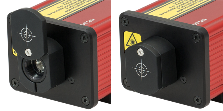
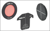
Click to Enlarge
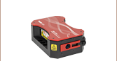
The shutter rotates open (left) and closed (right) and is held in position by magnets built into the shutter fixture. When the shutter is closed, the target on the cover indicates the approximate location of the beam.

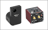
Click for Details
The MTD415L Temperature Controller regulates the temperature of the laser diode to stabilize optical output power and wavelength.

| Item # | NPL64A | NPL41B | NPL45B | NPL49B | NPL52B | NPL64B | NPL79B | NPL82B | NPL91B | NPL98B | |
|---|---|---|---|---|---|---|---|---|---|---|---|
| Center Wavelength (Typical) | 640 ± 10 nm | 405 ± 10 nm | 450 ± 10 nm | 488 ± 10 nm | 520 ± 10 nm | 640 ± 10 nm | 785 ± 10 nm | 820 ± 10 nm | 905 ± 10 nm | 980 ± 10 nm | |
| Pulse Width (FWHM) | Min, Setting 1a | 10 ± 1 nsb | 6 ± 1 ns | 5 ± 1 ns | 6 ± 1 ns | 5 ± 1 ns | 6 ± 1 ns | ||||
| Max, Setting 16a | 38 ± 3 ns | 39 ± 3 ns | 39 ± 3 ns | 39 ± 3 ns | 39 ± 3 ns | ||||||
| Typ. Pulse Width vs. Control Settinga,c | N/Ab |  |
 |
 |
 |
|
 |
 |
 |
 |
|
| Typical Pulsesc |  |
 |
 |
 |
 |
 |
 |
 |
 |
 |
|
| Internal Trigger | No | Yes (1, 5, or 10 MHz) | |||||||||
| Max Trigger Frequencyd |
10 MHz | ||||||||||
| Pulse Energy (Typical Max)e | 0.12 nJ | 1.5 nJ | 3.0 nJ | 2.0 nJ | 1.2 nJ | 2.0 nJ | 3.5 nJ | 3.5 nJ | 3.5 nJ | 1.5 nJ | |
| Average Power (Max)e |
1.2 mW | 15 mW | 30 mW | 20 mW | 12 mW | 20 mW | 35 mW | 35 mW | 35 mW | 15 mW | |
| Peak Power (Typical Max)f |
13 mW | 38 mW | 75 mW | 50 mW | 30 mW | 50 mW | 88 mW | 88 mW | 88 mW | 38 mW | |
| Output Spectrum (Typical)c |
 |
 |
 |
 |
 |
 |
 |
 |
 |
 |
|
| Beam Pointing Accuracyg | ≤3° | ||||||||||
| Beam Divergenceh (1/e2), Typical |
Major Axis | 1.5 mrad | 0.5 mrad | 0.5 mrad | 0.5 mrad | 1.5 mrad | 1.5 mrad | 0.3 mrad | 0.5 mrad | 1.0 mrad | 0.5 mrad |
| Minor Axis | 0.5 mrad | 0.3 mrad | 0.25 mrad | 0.3 mrad | 0.5 mrad | 0.5 mrad | 0.15 mrad | 0.6 mrad | 0.5 mrad | 0.5 mrad | |
| Beam Full Widthh (1/e2) at 5.0 m |
Major Axis | 5.3 mm | 2.5 mm | 3.3 mm | 3.0 mm | 3.2 mm | 4.8 mm | 3.8 mm | 2.9 mm | 5.0 mm | 2.6 mm |
| Minor Axis | 2.1 mm | 1.7 mm | 1.6 mm | 1.8 mm | 2.0 mm | 2.7 mm | 3.3 mm | 1.4 mm | 2.8 mm | 1.3 mm | |
| Output Beam Image (Typical)i,j | |||||||||||
| Item # | NPL41C | NPL45C | NPL52C | NPL64C | NPL81C | NPL94C | |
|---|---|---|---|---|---|---|---|
| Center Wavelength (Typical) | 405 ± 10 nm | 450 ± 10 nm | 520 ± 10 nm | 640 ± 10 nm | 808 ± 10 nm | 940 ± 10 nm | |
| Pulse Width (FWHM) | Min, Setting 1a | 6 ± 1 ns | |||||
| Max, Setting 16a | 129 ± 5 ns | ||||||
| Typ. Pulse Width vs. Control Settinga,b |  |
 |
 |
 |
 |
 |
|
| Typical Pulsesb |  |
 |
 |
 |
 |
 |
|
| Internal Trigger | No | ||||||
| Max Trigger Frequencyc |
50 kHz | ||||||
| Pulse Energy (Typical Max)d | 128 nJ | 204 nJ | 186 nJ | 126 nJ | 186 nJ | 129 nJ | |
| Average Power (Max)d |
6.4 mW | 10.2 mW | 9.3 mW | 6.3 mW | 9.3 mW | 6.5 mW | |
| Peak Power (Typical Max)e |
1000 mW | 1600 mW | 1500 mW | 1000 mW | 1500 mW | 1000 mW | |
| Output Spectrum (Typical)b |
 |
 |
 |
 |
 |
 |
|
| Beam Pointing Accuracyf | ≤3° | ||||||
| Beam Divergenceg (1/e2), Typical |
Major Axis | 4.9 mrad | 2.4 mrad | 3.7 mrad | 10.2 mrad | 9.5 mrad | 7.2 mrad |
| Minor Axis | 0.2 mrad | 0.14 mrad | 0.6 mrad | 0.5 mrad | 0.85 mrad | 0.28 mrad | |
| Beam Full Widthg (1/e2) at 5.0 m |
Major Axis | 21 mm | 19.2 mm | 16.5 mm | 43 mm | 49 mm | 47 mm |
| Minor Axis | 1 mm | 1.3 mm | 1.9 mm | 1.2 mm | 1.3 mm | 1.6 mm | |
| Output Beam Image (Typical)h,i | |||||||
| Trigger Specifications | ||
|---|---|---|
| Coupling | AC Coupled | |
| Max Input Frequencya |
Item #s Ending in A or B | 10 MHz |
| Item #s Ending in C | 50 kHz | |
| Input Voltage | 200 mVpp to 2 Vpp | |
| Input Impedance | 5 kΩ | |
| Output Voltageb | 900 mV (Hi-Z Load) 600 mV (50 Ω Load) |
|
| Max Jitterc | 20 ps RMS 100 ps Peak-to-Peak |
|
| Delay from External Trigger Input to Optical Outputd | 35 ± 5 ns | |
| Delay from Internal Trigger Output to Optical Outputb | 28 ± 5 ns | |
Click to Enlarge
Block diagram depicting the internal architecture of the laser head, which contains the pulser drive electronics, safety interlocks, trigger circuits, and temperature stabilization system. The dual-color (red/blue) LED status indicator is designed to be visible through most laser safety glasses.
| Power Specifications | |
|---|---|
| DC Input Voltage Range to Laser Head | 14 to 16 V |
| DC Input Current to Laser Head (Max) | 800 mA |
| AC Input Frequency Range to Power Supply | 50 - 60 Hz |
| AC Input Voltage to Power Supply | 100 to 240 V |
| Environmental and Physical Specifications | ||
|---|---|---|
| Operating Temperature Range | 10 to 40 °C | |
| Storage Temperature Range | 0 to 50 °C | |
| Humidity Range (RH) | 5 - 85% | |
| Trigger Connector on Back Panela | Female SMA | |
| Power Connector on Laser Head | Male Mini-XLR Type | |
| Dimensions (L x W x H) |
Without ECM225 Clamps | 139.6 mm x 61.5 mm x 48.7 mm (5.49" x 2.42" x 1.92") |
| With ECM225 Clamps | 139.6 mm x 61.5 mm x 54.7 mm (5.49" x 2.42" x 2.15") |
|
Back Panels of the Pulsed Laser Systems
Click to Enlarge
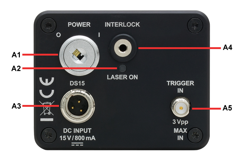
NPL64A Back Panel
| Callout | Description |
|---|---|
| A1 | Power Key Switch |
| A2 | LED Laser Status Indicator, Dual Color (Red/Blue) |
| A3 | Male Mini-XLR Connector for the +15 V Power Supply Jack |
| A4 | 2.5 mm Mono Phono Interlock Jacka |
| A5 | Female SMA for Trigger In |
Click to Enlarge
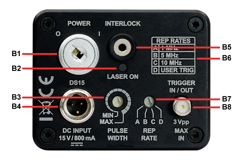
Back Panel of Item #s Ending in B
| Callout | Description |
|---|---|
| B1 | Power Key Switch |
| B2 | LED Laser Status Indicator, Dual Color (Red/Blue) |
| B3 | Pulse Width Selectora |
| B4 | Male Mini-XLR Connector for the +15 V Power Supply Jack |
| B5 | 2.5 mm Mono Phono Interlock Jackb |
| B6 | Chart of Repetition Rate Options vs. Selector Settings |
| B7 | Repetition Rate Selectora |
| B8 | Female SMA for Trigger In/Trigger Out |

Click to Enlarge
Back Panel of Item #s Ending in C
| Callout | Description |
|---|---|
| C1 | Power Key Switch |
| C2 | LED Laser Status Indicator, Dual Color (Red/Blue) |
| C3 | Pulse Width Selectora |
| C4 | Male Mini-XLR Connector for the +15 V Power Supply Jack |
| C5 | 2.5 mm Mono Phono Interlock Jackb |
| C6 | Female SMA for Trigger In |
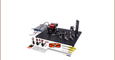
Components Included in Nanosecond Pulsed Laser Systems
Click to Enlarge
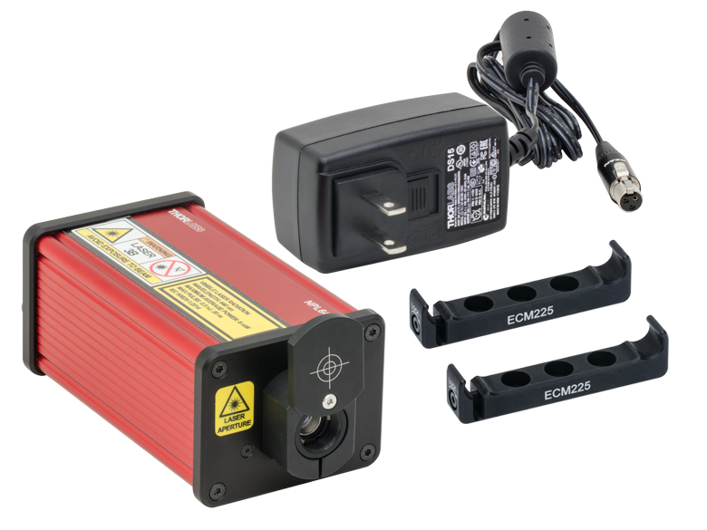
Item # Shown: NPL64A
Systems with Item #s Ending in A
- Laser Head with Integrated Drive Electronics and Temperature Stabilization Circuits
- DS15 +15 V Power Supply with Mini-XLR Type Connector and Location-Specific Plug
- Two ECM225 Aluminum Clamps
- Interlock Pin Installed in Interlock Port (Not Shown)
- Set of Keys for the Key Switch (Not Shown)
- Quick Start and Safety Guide (Not Shown)
Click to Enlarge
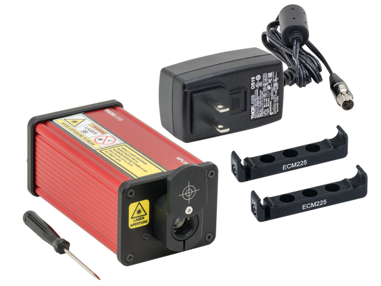
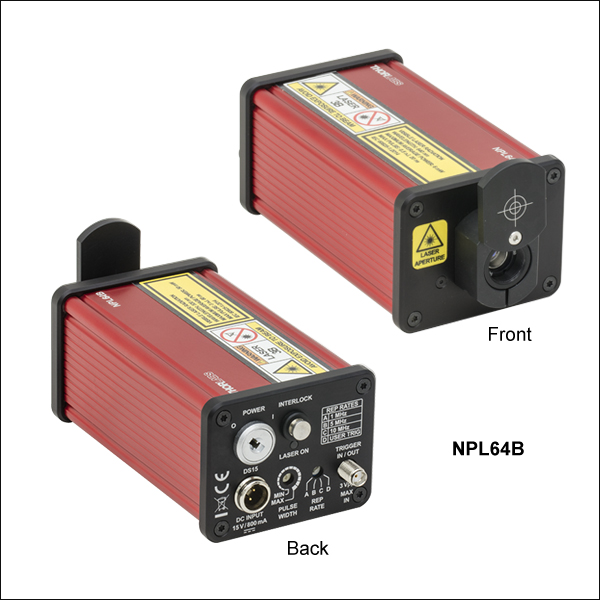
Item # Shown: NPL64B
Systems with Item #s Ending in B or C
- Laser Head with Integrated Drive Electronics and Temperature Stabilization Circuits
- DS15 +15 V Power Supply with Mini-XLR Type Connector and Location-Specific Plug
- Two ECM225 Aluminum Clamps
- Interlock Pin Installed in Interlock Port (Not Shown)
- Set of Keys for the Key Switch (Not Shown)
- A Flathead Screwdriver with a 2.5 mm Edge
- Quick Start and Safety Guide (Not Shown)
Laser Safety and Classification
Safe practices and proper usage of safety equipment should be taken into consideration when operating lasers. The eye is susceptible to injury, even from very low levels of laser light. Thorlabs offers a range of laser safety accessories that can be used to reduce the risk of accidents or injuries. Laser emission in the visible and near infrared spectral ranges has the greatest potential for retinal injury, as the cornea and lens are transparent to those wavelengths, and the lens can focus the laser energy onto the retina.
 |
 |
 |
 |
 |
 |
 |
 |
 |
Safe Practices and Light Safety Accessories
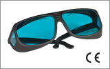
- Laser safety eyewear must be worn whenever working with Class 3 or 4 lasers.
- Regardless of laser class, Thorlabs recommends the use of laser safety eyewear whenever working with laser beams with non-negligible powers, since metallic tools such as screwdrivers can accidentally redirect a beam.
- Laser goggles designed for specific wavelengths should be clearly available near laser setups to protect the wearer from unintentional laser reflections.
- Goggles are marked with the wavelength range over which protection is afforded and the minimum optical density within that range.
- Laser Safety Curtains and Laser Safety Fabric shield other parts of the lab from high energy lasers.
- Blackout Materials can prevent direct or reflected light from leaving the experimental setup area.
- Thorlabs' Enclosure Systems can be used to contain optical setups to isolate or minimize laser hazards.
- A fiber-pigtailed laser should always be turned off before connecting it to or disconnecting it from another fiber, especially when the laser is at power levels above 10 mW.
- All beams should be terminated at the edge of the table, and laboratory doors should be closed whenever a laser is in use.
- Do not place laser beams at eye level.
- Carry out experiments on an optical table such that all laser beams travel horizontally.
- Remove unnecessary reflective items such as reflective jewelry (e.g., rings, watches, etc.) while working near the beam path.
- Be aware that lenses and other optical devices may reflect a portion of the incident beam from the front or rear surface.
- Operate a laser at the minimum power necessary for any operation.
- If possible, reduce the output power of a laser during alignment procedures.
- Use beam shutters and filters to reduce the beam power.
- Post appropriate warning signs or labels near laser setups or rooms.
- Use a laser sign with a lightbox if operating Class 3R or 4 lasers (i.e., lasers requiring the use of a safety interlock).
- Do not use Laser Viewing Cards in place of a proper Beam Trap.
Laser Classification
Lasers are categorized into different classes according to their ability to cause eye and other damage. The International Electrotechnical Commission (IEC) is a global organization that prepares and publishes international standards for all electrical, electronic, and related technologies. The IEC document 60825-1 outlines the safety of laser products. A description of each class of laser is given below:
| Class | Description | Warning Label |
|---|---|---|
| 1 | This class of laser is safe under all conditions of normal use, including use with optical instruments for intrabeam viewing. Lasers in this class do not emit radiation at levels that may cause injury during normal operation, and therefore the maximum permissible exposure (MPE) cannot be exceeded. Class 1 lasers can also include enclosed, high-power lasers where exposure to the radiation is not possible without opening or shutting down the laser. |  |
| 1M | Class 1M lasers are safe except when used in conjunction with optical components such as telescopes and microscopes. Lasers belonging to this class emit large-diameter or divergent beams, and the MPE cannot normally be exceeded unless focusing or imaging optics are used to narrow the beam. However, if the beam is refocused, the hazard may be increased and the class may be changed accordingly. |  |
| 2 | Class 2 lasers, which are limited to 1 mW of visible continuous-wave radiation, are safe because the blink reflex will limit the exposure in the eye to 0.25 seconds. This category only applies to visible radiation (400 - 700 nm). |  |
| 2M | Because of the blink reflex, this class of laser is classified as safe as long as the beam is not viewed through optical instruments. This laser class also applies to larger-diameter or diverging laser beams. |  |
| 3R | Class 3R lasers produce visible and invisible light that is hazardous under direct and specular-reflection viewing conditions. Eye injuries may occur if you directly view the beam, especially when using optical instruments. Lasers in this class are considered safe as long as they are handled with restricted beam viewing. The MPE can be exceeded with this class of laser; however, this presents a low risk level to injury. Visible, continuous-wave lasers in this class are limited to 5 mW of output power. |  |
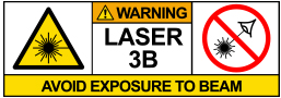
| 3B | Class 3B lasers are hazardous to the eye if exposed directly. Diffuse reflections are usually not harmful, but may be when using higher-power Class 3B lasers. Safe handling of devices in this class includes wearing protective eyewear where direct viewing of the laser beam may occur. Lasers of this class must be equipped with a key switch and a safety interlock; moreover, laser safety signs should be used, such that the laser cannot be used without the safety light turning on. Laser products with power output near the upper range of Class 3B may also cause skin burns. |  |
| 4 | This class of laser may cause damage to the skin, and also to the eye, even from the viewing of diffuse reflections. These hazards may also apply to indirect or non-specular reflections of the beam, even from apparently matte surfaces. Great care must be taken when handling these lasers. They also represent a fire risk, because they may ignite combustible material. Class 4 lasers must be equipped with a key switch and a safety interlock. |  |
| All class 2 lasers (and higher) must display, in addition to the corresponding sign above, this triangular warning sign. |  |
|

Adam Knapp
Ultrafast Optoelectronics
General Manager
Custom and OEM Options
When your application requirements are not met by our range of catalog products or their variety of user-configurable features, please contact me to discuss how we may serve your custom or OEM needs.
Request a Demo Unit
Explore the benefits of using a Thorlabs high-speed instrument in your setup and under your test conditions with a demo unit. Contact me for details.
![]()

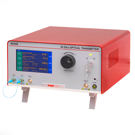
Click to Enlarge
Figure 162A The MX40B Digital Reference Transmitter
Design, Manufacturing, and Testing Capabilities
Thorlabs' Ultrafast Optoelectronics Team designs, develops, and manufactures high-speed components and instrumentation for a variety of photonics applications having frequency responses up to 110 GHz. Our extensive experience in high-speed photonics is supported by core expertise in RF/microwave design, optics, fiber optics, optomechanical design, and mixed-signal electronics. As a division of Thorlabs, a company with deep vertical integration and a portfolio of over 20,000 products, we are able to provide and support a wide selection of equipment and continually expand our offerings.
Our catalog and custom products include a range of integrated fiber-optic transmitters, modulator drivers and controllers, detectors, receivers, pulsed lasers, variable optical attenuators, and a variety of accessories. Beyond these products, we welcome opportunities to design and produce custom and OEM products that fall within our range of capabilities and expertise. Some of our key capabilities are:
- Detector and Receiver Design, to 70 GHz
- Fiber-Optic Transmitter Design, to 110 GHz
- RF & Microwave Design and Simulation
- Design of Fiber-Optic and Photonics Sub-Assemblies
- High-Speed Testing, to 110 GHz
- Micro-Assembly and Wire Bonding
- Hermetic Sealing of Microwave Modules
- Fiber Splicing of Assemblies
- Custom Laser Engraving
- Qualification Testing
Overview of Custom and Catalog Products
Our catalog product line includes a range of integrated fiber-optic transmitters, modulator drivers and controllers, detectors, pulsed lasers, and accessories. In addition to these, we offer related items, such as receivers and customized catalog products. The following sections give an overview of our spectrum of custom and catalog products, from fully integrated instruments to component-level modules.
Fiber-Optic Instruments
To meet a range of requirements, our fiber-optic instruments span a variety integration levels. Each complete transmitter includes a tunable laser, a modulator with driver amplifier and bias controller, full control of optical output power, and an intuitive touchscreen interface. The tunable lasers, modulator drivers, and modulator bias controllers are also available separately. These instruments have full remote control capability and can be addressed using serial commands sent from a PC.
- Fiber-Optic Transmitters, to 110 GHz
- Linear and Digital Transmitters
- Electrical-to-Optical Converters, to 110 GHz
- Modulator Drivers
- Modulator Bias Controllers
- C- and L-Band Tunable Lasers
Customization options include internal laser sources, operating wavelength ranges, optical fiber types, and amplifier types.
Fiber-Optic Components
Our component-level, custom and catalog fiber-optic products take advantage of our module design and hermetic sealing capability. Products include detectors with frequency responses up to 50 GHz, and we also specialize in developing fiber-optic receivers, operating up to and beyond 40 GHz, for instrumentation markets. Closely related products include our amplifier modules, which we offer upon request, variable optical attenuators, microwave cables, and cable accessories.
- Hermetically-Sealed Detectors, to 50 GHz
- Fiber-Optic Receivers, to 40 GHz
- Amplifier Modules
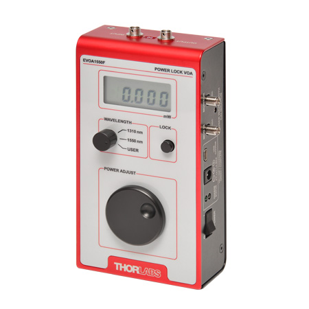
- Electronic Variable Optical Attenuators
- Microwave Cables and Accessories
Customization options include single mode and multimode optical fiber options, where applicable, and detectors optimized for time or frequency domain operation.
Free-Space Instruments
Our free-space instruments include detectors with frequency responses around 1 GHz and pulsed lasers. Our pulsed lasers generate variable-width, nanosecond-duration pulses, and a range of models with different wavelengths and optical output powers are offered. User-adjustable repetition rates and trigger in/out signals provide additional flexibility, and electronic delay-line products enable experimental synchronization of multiple lasers. We can also adapt our pulsed laser catalog offerings to provide gain-switching capability for the generation of pulses in the 100 ps range.
- Pulsed Lasers with Fixed 10 ns Pulse Duration
- Pulsed Lasers with Variable Pulse Width and Repetition Rates
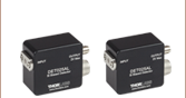
- Electronic Delay Units to Synchronize NPL Series Pulsed Lasers
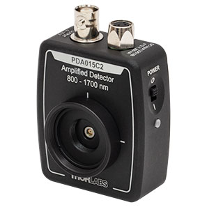
- Amplified Detectors
Customization options for the pulsed lasers include emission wavelength, optical output powers, and sub-nanosecond pulse widths.

Click to Enlarge
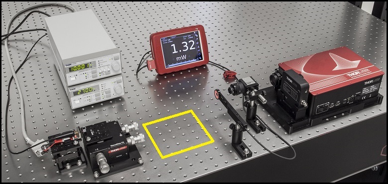
Figure 168A The beam circularization systems were placed in the area of the experimental setup highlighted by the yellow rectangle.


Comparison of Circularization Techniques for Elliptical Beams
Edge-emitting laser diodes emit elliptical beams as a consequence of the rectangular cross sections of their emission apertures. The component of the beam corresponding to the narrower dimension of the aperture has a greater divergence angle than the orthogonal beam component. As one component diverges more rapidly than the other, the beam shape is elliptical rather than circular.
Elliptical beam shapes can be undesirable, as the spot size of the focused beam is larger than if the beam were circular, and as larger spot sizes have lower irradiances (power per area). Techniques for circularizing an elliptical beam include those based on a pair of cylindrical lenses, an anamorphic prism pair, or a spatial filter. This work investigated all three approaches. The characteristics of the circularized beams were evaluated by performing M2 measurements, wavefront measurements, and measuring the transmitted power.
While it was demonstrated that each circularization technique improves the circularity of the elliptical input beam, each technique was shown to provide a different balance of circularization, beam quality, and transmitted power. The results of this work, which are documented in this Lab Fact, indicate that an application's specific requirements will determine which is the best circularization technique to choose.
Experimental Design and Setup
The experimental setup is shown in Figure 168A. The elliptically-shaped, collimated beam of a temperature-stabilized 670 nm laser diode was input to each of our circularization systems shown in Figures 168B through 168D. Collimation results in a low-divergence beam, but it does not affect the beam shape. Each system was based on one of the following:
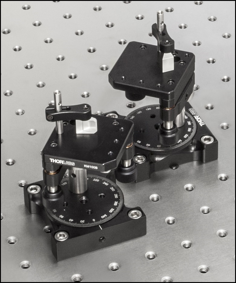
- LJ1874L2-A and LJ1638L1-A Plano-Convex Convex Cylindrical Lenses (Figure 168B)
- PS873-A Unmounted Anamorphic Prism Pair (Figure 168C)
- Previous Generation KT310 Spatial Filter System with P5S Ø5 µm Pinhole (Figure 168D)
The beam circularization systems, shown in Figures 168B through 168D, were placed, one at a time, in the vacant spot in the setup highlighted by the yellow rectangle. With this arrangement, it was possible to use the same experimental conditions when evaluating each circularization technique, which allowed the performance of each to be directly compared with the others. This experimental constraint required the use of fixturing that was not optimally compact, as well as the use of an unmounted anamorphic prism pair, instead of a more convenient mounted and pre-aligned anamorphic prism pair.
The characteristics of the beams output by the different circularization systems were evaluated by making measurements using a power meter, a wavefront sensor, and an M2 system. In the image of the experimental setup shown in Figure 168A, all of these systems are shown on the right side of the optical table for illustrative purposes; they were used one at a time. The power meter was used to determine how much the beam circularization system attenuated the intensity of the input laser beam. The wavefront sensor provided a way to measure the aberrations of the output beam. The M2 system measurement describes the resemblance of the output beam to a Gaussian beam. Ideally, the circularization systems would not attenuate or aberrate the laser beam, and they would output a perfectly Gaussian beam.
Edge-emitting laser diodes also emit astigmatic beams, and it can be desirable to force the displaced focal points of the orthogonal beam components to overlap. Of the three circularization techniques investigated in this work, only the cylindrical lens pair can also compensate for astigmatism. The displacement between the focal spots of the orthogonal beam components were measured for each circularization technique. In the case of the cylindrical lens pair, their configuration was tuned to minimize the astigmatism in the laser beam. The astigmatism was reported as a normalized quantity.
Experimental Results
The experimental results are summarized in Table 168E, in which the green cells identify the best result in each category. Each circularization approach has its benefits. The best circularization technique for an application is determined by the system’s requirements for beam quality, transmitted optical power, and setup constraints.
Spatial filtering significantly improved the circularity and quality of the beam, but the beam had low transmitted power. The cylindrical lens pair provided a well-circularized beam and balanced circularization and beam quality with transmitted power. In addition, the cylindrical lens pair compensated for much of the beam's astigmatism. The circularity of the beam provided by the anamorphic prism pair compared well to that of the cylindrical lens pair. The beam output from the prisms had better M2 values and less wavefront error than the cylindrical lenses, but the transmitted power was lower.
| Table 168E Experimental Results | ||||||
|---|---|---|---|---|---|---|
| Method | Beam Intensity Profile | Circularitya | M2 Values | RMS Wavefront | Transmitted Power | Normalized Astigmatismb |
| Collimated Source Output (No Circularization Technique) |
 Click to Enlarge Scale in Microns |
0.36 | Y Axis: 1.63 |
0.17 | Not Applicable | 0.67 |
| Cylindrical Lens Pair |  Click to Enlarge Scale in Microns |
0.84 | X Axis: 1.90 Y Axis: 1.93 |
0.30 | 91% | 0.06 |
| Anamorphic Prism Pair |
 Click to Enlarge Scale in Microns |
0.82 | X Axis: 1.60 Y Axis: 1.46 |
0.16 | 80% | 1.25 |
| Spatial Filter | 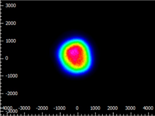 Click to Enlarge Scale in Microns |
0.93 | X Axis: 1.05 Y Axis: 1.10 |
0.10 | 34% | 0.36 |
Components used in each circularization system were chosen to allow the same experimental setup be used for all experiments. This had the desired effect of allowing the results of all circularization techniques to be directly compared; however, optimizing the setup for a circularization technique could have improved its performance. The mounts used for the collimating lens and the anamorphic prism pair enabled easy manipulation and integration into this experimental system. It is possible that using smaller mounts would improve results by allowing the members of each pair to be more precisely positioned with respect to one another. In addition, using made-to-order cylindrical lenses with customized focal lengths may have improved the results of the cylindrical lens pair circularization system. All results may have been affected by the use of the beam profiler software algorithm to determine the beam radii used in the circularity calculation.
Additional Information
Some information describing selection and configuration procedures for several components used in this experimental work can be accessed by clicking the following hyperlinks:
Pulsed Laser Emission: Power and Energy Calculations

Determining whether emission from a pulsed laser is compatible with a device or application can require referencing parameters that are not supplied by the laser's manufacturer. When this is the case, the necessary parameters can typically be calculated from the available information. Calculating peak pulse power, average power, pulse energy, and related parameters can be necessary to achieve desired outcomes including:
- Protecting biological samples from harm.
- Measuring the pulsed laser emission without damaging photodetectors and other sensors.
- Exciting fluorescence and non-linear effects in materials.
Pulsed laser radiation parameters are illustrated in Figure 170A and described in Table 170B. For quick reference, a list of equations is provided below. The document available for download provides this information, as well as an introduction to pulsed laser emission, an overview of relationships among the different parameters, and guidance for applying the calculations.
|
Equations: |
||||
 |
and |  |
||
 |
||||
 |
||||
 |
||||
Peak power and average power calculated from each other: |
||||
 |
and |  |
||
| Peak power calculated from average power and duty cycle*: | ||||
 |
*Duty cycle ( ) is the fraction of time during which there is laser pulse emission. ) is the fraction of time during which there is laser pulse emission. |
|||
Click to Enlarge
Figure 170A Parameters used to describe pulsed laser emission are indicated in this plot and described in Table 170B. Pulse energy (E) is the shaded area under the pulse curve. Pulse energy is, equivalently, the area of the diagonally hashed region.
| Table 170B Pulse Parameters | |||||
|---|---|---|---|---|---|
| Parameter | Symbol | Units | Description | ||
| Pulse Energy | E | Joules [J] | A measure of one pulse's total emission, which is the only light emitted by the laser over the entire period. The pulse energy equals the shaded area, which is equivalent to the area covered by diagonal hash marks. | ||
| Period | Δt | Seconds [s] | The amount of time between the start of one pulse and the start of the next. | ||
| Average Power | Pavg | Watts [W] | The height on the optical power axis, if the energy emitted by the pulse were uniformly spread over the entire period. | ||
| Instantaneous Power | P | Watts [W] | The optical power at a single, specific point in time. | ||
| Peak Power | Ppeak | Watts [W] | The maximum instantaneous optical power output by the laser. | ||
| Pulse Width |  |
Seconds [s] | A measure of the time between the beginning and end of the pulse, typically based on the full width half maximum (FWHM) of the pulse shape. Also called pulse duration. | ||
| Repetition Rate | frep | Hertz [Hz] | The frequency with which pulses are emitted. Equal to the reciprocal of the period. | ||
Example Calculation:
Is it safe to use a detector with a specified maximum peak optical input power of 75 mW to measure the following pulsed laser emission?
- Average Power: 1 mW
- Repetition Rate: 85 MHz
- Pulse Width: 10 fs
The energy per pulse:

seems low, but the peak pulse power is:

It is not safe to use the detector to measure this pulsed laser emission, since the peak power of the pulses is >5 orders of magnitude higher than the detector's maximum peak optical input power.
| Posted Comments: | |
森 耿
(posted 2025-02-21 21:26:26.83) 我想要咨询NPL79B - 纳秒脉冲激光二极管系统,785 nm,可调脉宽:6 - 39 ns这款激光器的详细情况 cdolbashian
(posted 2025-02-28 11:59:37.0) Thank you for reaching out to us with this inquiry! We have contacted you directly to answer any specific questions regarding the specifications and functionality of the NPL79B. Giorgos Stavrakakis
(posted 2024-10-14 12:12:08.693) Dear Sir/Madam
My name is Giorgos Stavrakakis, currently a PhD candidate at Chemistry Department at University of Crete (Greece) and a member of LBMI group at FORTH, Crete as well.
Concerning the item NPL81C, I’m interested in custom-made single wavelength pulsed laser diodes, one emitting at 680 nm and the other at 770 nm. As for the laser specifications, pulse width shall be 100 ps-10 ns,
repetition rate 1 kHz-10kHz and pulse energy >500 nJ.
Looking forward for your reply
Kind regards tdevkota
(posted 2024-10-15 05:26:59.0) Thank you for reaching out to Thorlabs. I have contacted you directly to discuss the feasibility of custom wavelengths. Louis Obeid Mogridge
(posted 2024-05-07 16:26:09.42) Hi there,
we are interested in buying a NPL45B. But, we would need to couple the output into a optical fiber. What would be the best way to do this? And what fiber would you recommend for coupling? Either multi-mode or single-mode is fine for our purposes.
Many thanks,
Louis. cdolbashian
(posted 2024-05-10 04:31:57.0) Thank you for reaching out to us with this inquiry. Single mode fiber coupling will be extremely lossy, as the mode of the laser output is not a TEM00 (gaussian) output, so you would inherently not be able to propagate all of the laser modes.
If there is no real difference to you, I would recommend some multimode fiber with a core of ≥400um. a typical setup would involve a single convex lens which would focus the beam to a small spot on the tip of your fiber. The fiber should be placed on some sort of x-y translation stage, as well as having adjustable z position so that you can ensure that your beam is centered on the fiber, as well as located properly at the beam waist. I have contacted you directly to expound on this further. Alastair Curnock
(posted 2024-04-29 13:11:47.24) Good Afternoon
For the NPL41B, could you confirm if the output is activated on the rising or falling edge of an external trigger pulse.
Thanks cdolbashian
(posted 2024-05-02 09:06:33.0) Thank you for reaching out with this inquiry! The pulse triggers on the rising edge. Alastair Curnock
(posted 2024-04-17 13:51:25.127) Good Afternoon
We are very interested in using the NPL41B pulsed laser, but I have a couple of questions :
1) Do you have any information regarding the repeatability of pulse energy from pulse to pulse
2) could you recommend a coupler to connect this is a fibre optic with 400um core and 0.22NA with and SMA connector.
Many Thanks cdolbashian
(posted 2024-05-06 01:21:18.0) Thank you for reaching out to us with this inquiry. The repeatability can depend on the exact pulse setting used and total time considered however we estimate the pulse-to-pulse variation in intensity and width are each less than 1%. We have seen customer used the adjustable collimators like CFCS8-A mounted in an LM1XY with an AD15F adapter to aid in alignment for coupling into a fiber. I have reached out directly to discuss this application in further detail. Darren Earl
(posted 2023-09-21 07:31:46.457) Hello,
I am interested in the NPL79B but would prefer it to be fiber coupled (FC/PC or FC/APC). Do you have any suggestions on accessories to allow this. Even if there is significant coupling loss.
Many thanks
Darren Earl jpolaris
(posted 2023-09-22 12:13:36.0) Thank you for contacting Thorlabs. For coupling the light from an NPL79B laser into a fiber, we recommend using an adjustable collimator such as CFC8-B or CFC11P-B, mounted in an LM1XY post-mountable translation mount. You can use an AD15F2 adapter to mount the CFC-series adjustable collimators in LM1XY. We have found the beam profile of these NPL79B to stabilize ~20 cm from the output aperture. To optimize coupling efficiency into your fiber, we recommend placing the CFC-series collimator ~20 cm or further from the NPL79B. With this configuration, we have seen > 80% coupling efficiency into 50 μm core multimode fibers such as FG050LGA. Our M42L01 is a 1 m, FC/PC connectorized patch cable using FG050LGA. Into single mode fibers such as 780HP, coupling efficiencies in the 20% - 30% range are typical. Our P1-780A-FC-1 is a 1 m, FC/PC connectorized patch cable using 780HP. Mathieu Perrin
(posted 2023-07-11 17:50:13.9) Hi, I would need some more information about the beam quality or focusability of these lasers in order to work out the expected fluence after circularization and focusing. Are they transverse monomode ? What is the M² in both directions ? I am more particularly interested in the -C lasers.
(Note: the quoted values of beam diameters for the minor axis suggest that the waist is located after the collimating lens, out of the laser.) cdolbashian
(posted 2023-07-21 01:56:06.0) Thank you for emailing us with this inquiry. Although we do not specify an M2 value for the C series of lasers we do have results for fiber coupling of these devices into optical fibers which gives you an idea of the beam quality. For the C series of NPLs we can achieve 20% coupling into single mode fiber and 80% coupling into multimode fiber (50 or 62.5 um core). user
(posted 2023-03-30 18:29:58.597) Hello, I am using NPL41C. However, it is having difficulty adjusting the pulse width. I am measuring the laser using PMT and oscilloscope, but pulse width is not nanosecond (Almost 1 us). How can I solve it? ksosnowski
(posted 2023-03-30 03:31:38.0) Hello, thanks for reaching out to Thorlabs. NPL41C's adjustable pulse width only goes up to 129ns, so it is more likely that the detector and amplifier in your system are bandwidth limited, and causing some apparent skew in rise/fall times. I have reached out directly to discuss your application in greater detail. Sarit Israeli
(posted 2023-03-16 00:32:51.827) Does Thorlabs has a product like NPL91B but with 940nm laser instead of 905nm? ksosnowski
(posted 2023-03-16 04:49:10.0) Hello Sarit, thanks for reaching out to Thorlabs. Currently we do not have any NPL series or other similar pulsed lasers around 940nm. NPL98B has CWL 980nm which is the next closest to this. Victor Garcia Muñoz
(posted 2023-02-21 14:41:33.477) hi,
What is the lower repetition rate?
Can we work @10Hz for the shortest pulse width?
Thanks, Victor jdelia
(posted 2023-02-23 01:25:34.0) Thank you for contacting Thorlabs. The NPL- series lasers do not have a minimum rep rate. They have been used in low-rep rate and even single shot applications. Yes, you can use the NPL64C at 10 Hz. user
(posted 2023-01-09 17:41:10.39) Clarification required regarding external trigger jitter of NPL52C
The delay spec 35+/-5nsec is it for unit to unit variability or its short term instability from external trigger to optical output cdolbashian
(posted 2023-01-23 12:01:23.0) Thank you for reaching out to us with this inquiry. From the web page specs, it seems like we list this as the time delay between the input trigger signal and the output optical signal. I have reached out to you directly to further discuss this. Soocheol Kim
(posted 2022-05-23 15:36:33.4) I tried to acquire a photodetector by driving a pulse laser with a trigger signal of 10 kHz.
It would be easier to understand if I show the graph I have acquired, but I will explain it in words.
Although the pulses come out with a period of 10 kHz, the pulse power changes with a certain period (132~133 Hz). cdolbashian
(posted 2022-05-27 12:57:56.0) Thank you for reaching out to us with this inquiry! As you mentioned troubleshooting this will be easier with some visible data. I have reached out to you directly to troubleshoot the erroneous behavior which you are seeing. Matias Berasategui
(posted 2022-05-19 09:28:28.173) Hello,
My name is Matias Berasategui. I work at the Helmholtz-Zentrum Berlin and I am interested in purchasing the NPL81C laser (808nm with 1500mW Peak Power), and I would like to ask if you can provide the equivalent for 980nm. Is it possible to buy a 980nm nanosecond laser with 1500mW Peak Power?
Thank you very much,
Matias Berasategui. jdelia
(posted 2022-05-19 09:44:43.0) Thank you for contacting Thorlabs. We are reaching out to you directly to discuss the feasibility of this custom part. Alex Mokhnatyuk
(posted 2021-09-09 18:36:31.77) Please can you provide mounting holes with thread for fiber port PAF2 on laser exit flange? This would be very helpful. YLohia
(posted 2021-09-17 05:01:31.0) Hello, thank you for your feedback! We will certainly consider your suggestion for a future revision/iteration of this product line. Storm Liao
(posted 2021-05-24 17:37:25.573) Dear sirs,
I can't find trigger out function on NPL52C, and how can I synchronized NPL52c with our oscilloscope?
Best regards,
Storm YLohia
(posted 2021-05-27 02:32:34.0) Hello Storm, the C series of these nanosecond lasers don't have a built in trigger, so there is no trigger output function. If you would like to sync the laser pulses with your scope, you will have to use a direct output from your function generator and connect that to your scope. Lee Aspitarte
(posted 2021-02-16 16:57:00.223) Hi, I am using the NPL64B laser, and I am having issues with the system turning off intermittently. I hear an audible click, but the light on the back stays on (which doesn't appear to be the case with triggering the interlock). This happens with somewhat random timing and happens regardless of the trigger setting. Is it possible the TEC is overheating and suppressing the diode temporarily? YLohia
(posted 2021-03-15 03:26:32.0) Thank you for contacting Thorlabs. We are sorry to hear about the issues you're experiencing with the NPL. What is the serial number of your NPL64B and what was the Thorlabs Sales Order Number under which it was purchased? Have you always had this issue or is this a recent problem?
What is the environmental temperature (and humidity) at which you're using this? Are there any backreflections going into the laser?
Does this problem occur if you use a shorter pulse width and a much lower rep rate (from external trigger), on the order of a few Hz? This would prevent the LD from generating a lot of heat and can tell us if this is a TEC issue or not. I have reached out to you directly to troubleshoot further. liangze pan
(posted 2020-07-02 15:04:15.147) Hello, would you mind provide the specific data of the spetcral distribution of laser source NPL64B at each control setting? If not, would you mind provide the data of typical spectral distribution?Thanks! YLohia
(posted 2020-07-02 10:34:26.0) Hello, thank you for contacting Thorlabs. The spectrum will not change much as a function of pulse width. Please refer to the typical spectrum plot we have on the Specs tab. While we don’t have this type of granular data, we have seen some change in spectral response as a function of duty cycle. For duty cycles near the maximum (40%), we have seen that the spectrum collapses into a smaller number of modes. Thomas Allison
(posted 2019-08-14 16:15:43.627) Can you make one of these pulsed lasers at 1035 nm (or 1030 would be close enough). This would be very helpful for diagnosing my cavity via ringdown. YLohia
(posted 2019-08-15 08:28:24.0) Hello, thank you for your interest in our products. I have reached out to you directly to discuss the possibility of offering this. K. Morgan
(posted 2019-04-19 17:15:12.963) What is the output polarization of the beam? YLohia
(posted 2019-04-22 10:57:51.0) Hello, thank you for contacting Thorlabs. The output of these lasers is linearly polarized. When we build our NPLs, we align the ellipticity of the beam to the housing with ±5 degrees accuracy. Polarization follows this, so the NPLCs are vertically polarized with respect to the housing. We have measured the PER to be > 100:1 (and as high as 500:1 for the NPL41C and NPL52B). chien
(posted 2018-07-10 12:30:30.163) We would like to use the NPL41B with a wave guide. I found that the output of NPL41B has SM05 series internal thread. Do you have a wave guide that I can use? I could not find an appropriate one on your site.
Thanks alo.
Best regards, YLohia
(posted 2018-07-10 09:08:40.0) Hello, thank you for contacting Thorlabs. You may use one of our modules from this page (https://www.thorlabs.com/navigation.cfm?guide_id=27) to couple the light into a fiber of your choice. I will reach out to you directly to discuss your specific requirements for a particular part recommendation. aspitarte
(posted 2018-05-01 11:14:27.127) Hi, Can you answer the questions about the safety compliance of these lasers and the power supply?
Is device classified per Center for Devices and Radiological Health (CDRH)?
Is device listed / approved by an (Nationally Recognized Testing Laboratory) NRTL*? YLohia
(posted 2018-05-01 04:19:51.0) Hello, thank you for contacting Thorlabs. The lasers shown on this page are classified with the CDRH and have accession numbers. The FDA Accession Number for the NPL64A is 1710115-000. The products themselves are currently not tested by an NRTL. However, the power supplies for these lasers do have NRTL certifications. The DS15 power supply used in the NPL family of products is UL Listed. I have reached out to you directly with additional information about these certifications. wenzel.jakob
(posted 2017-11-28 20:12:52.39) Could you provide information on the on the dimensions of the beam if collimated using the included lens? (I am primarily interested in the 405nm device, i.e. NPL41B) tfrisch
(posted 2017-12-06 04:10:31.0) Hello, thank you for contacting Thorlabs. The NPL41B has a typical beam size of 4mmx2.5mm at 20ft. h.wu
(posted 2017-11-01 10:13:17.097) Could I set the repetition rate to be 1 ~ 20 Hz by an external trigger? Thank you. tfrisch
(posted 2017-12-19 02:43:09.0) Hello, thank you for contacting Thorlabs. Those slow rep rates would be achievable as long as the triggering edge has a transition time of 1ms or less. I will reach out to you to discuss your application. jonas.wietek
(posted 2017-08-03 21:02:00.107) is it possible to somehow only get a single laser pulse? tfrisch
(posted 2017-08-17 03:59:23.0) Hello, thank you for contacting Thorlabs. The trigger can be used to produce a single pulse. The pulse width may be slightly different for a single pulse compared to a high rep rate pulse. I will reach out to you directly to discuss your application. pavel.psota
(posted 2017-05-07 17:04:31.84) Dear madam or sir, I join the previous question considering spectral bandwidth? Is the source suitable for interferometric applications?
Thank you. Regards,Pavel tfrisch
(posted 2017-05-18 05:13:32.0) Hello Pavel, thank you for contacting Thorlabs. The bandwidths of these lasers are a few nm, so whether they can be used in an interferometric application depends on the coherence length required. I will reach out to you to share spectral data we have collected, and I expect we will publish similar curves to our webpage soon. ahmed
(posted 2017-03-26 05:05:01.763) Dear Sir/Madam
regarding your product (NPL64B) Nanosecond Pulsed Lasers.
Kindly can you provide me with the spectral bandwidth in nanometer for this laser?
and if you can provide me with an image for the optical spectrum analyzer signal for the same laser.
Thank you in advance for your help
Best Regards tfrisch
(posted 2017-04-18 03:12:34.0) Hello, thank you for contacting Thorlabs. The diode inside is a Fabry-Perot laser diode with several modes. I will contact you directly with more information. mojtaba.zamani.a
(posted 2017-02-23 03:13:02.39) Its nice to see these new grate products.well done! tfrisch
(posted 2017-03-03 07:57:23.0) Hello, thank you for your feedback, it is good to know these will be useful in customer applications. |

 Zoom
Zoom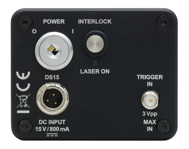
Click to Enlarge
Back Panel (See the Back Panels Tab for Additional Information)
- Typical Center Wavelength: 640 nm ± 10 nm
- Fixed 10 ns Pulse Width
- User-Supplied External Trigger Required to Generate Pulses
- Trigger Signal Input via SMA Connector on Back Panel
- 10 MHz Max Repetition Rate
This 640 nm wavelength pulsed laser system outputs fixed-duration 10 ns pulses in response to a user-supplied trigger input sent to the Trigger In port on the back panel of the laser head, shown in the image to the right. Pulses may be triggered at rates up to 10 MHz. A plot of a typical pulse is located in the table below. The aspheric lens integrated into the laser head is permanently fixed and factory set to collimate the optical output.
Please see the Back Panels tab and manual for more information about the features on the back panel.
This laser system includes the laser head, a +15 V power supply, and two ECM225 clamps for post mounting the laser head. Please see the Shipping List tab for a complete list of included components.
| Key Specificationsa | |||||||||
|---|---|---|---|---|---|---|---|---|---|
| Item # | Center Wavelength (Typ.) |
Output Spectrum (Typ.) |
Pulse Width |
Typical Pulse |
Pulse Energy (Typ. Max)b |
Peak Power (Typ. Max)c |
Average Power (Max)b |
External Trigger Frequency (Max)d |
Internal Trigger |
| NPL64A | 640 ± 10 nm |  |
10 ns | 0.12 nJ | 13 mW | 1.2 mW | 10 MHz | No | |

 Zoom
Zoom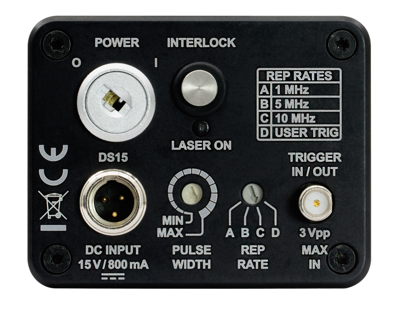
Click to Enlarge
Back Panel (See the Back Panels Tab for Additional Information)
- User-Adjustable Pulse Width (See Table Below)
- Generate Pulses with or without a User-Supplied Trigger
- Internally Triggered Pulse Rates of 1, 5, and 10 MHz
- Trigger Signal Input/Output via SMA Connector on Back Panel
- 10 MHz Max Repetition Rate
These nanosecond pulsed laser systems produce adjustable-duration nanosecond pulses in response to a user-supplied trigger input sent to the Trigger In port on the back panel of the laser head, shown in the image to the right. Pulses may be triggered at rates up to 10 MHz. These lasers also incorporate an internal trigger, enabling repetition frequencies of 1, 5, or 10 MHz. The aspheric lens integrated into the laser head is permanently fixed and factory set to collimate the optical output.
Pulse widths are adjustable from 5 to 39 ns over 16 discrete settings with approximately equal spacing. The specific pulse width range depends on the Item # as specified in the table below; please see the Specs tab for more information. Plots of typical pulses are also located in the table below. The controls for adjusting the pulse width and repetition rate are located on the back panel. The included 2.5 mm flathead screwdriver can be used to operate these controls.
The Rep Rate selector on the back panel enables the user to either choose among three options for internally triggering the pulses, or to configure the laser to accept a user-supplied external signal to trigger pulse generation. The internal pulse trigger is generated by oscillators in the laser head, and positions A, B, and C on the Rep Rate selector correspond to internally triggered repetition frequencies of 1, 5, and 10 MHz, respectively. When pulses are internally triggered, the Trigger IN/OUT port provides an output signal that is synchronized with the pulse generation. Alternatively, when the Rep Rate selector is set to position D, pulses are generated in response to an external trigger signal applied to the Trigger IN/OUT port. With this option, pulses may be triggered at rates up to 10 MHz. Please see the Back Panels tab and manual for more information about the features on the back panel.
These laser systems include the laser head, a +15 V power supply, a 2.5 mm flathead screwdriver, and two ECM225 clamps for post mounting the laser head. Please see the Shipping List tab for a complete list of included components.
| Key Specificationsa | |||||||||
|---|---|---|---|---|---|---|---|---|---|
| Item # | Center Wavelength (Typ.) |
Output Spectrum (Typ.) |
Pulse Width |
Typical Pulses |
Pulse Energy (Typ. Max)b |
Peak Power (Typ. Max)c |
Average Power (Max)b |
External Trigger Frequency (Max)d |
Internal Trigger |
| NPL41B | 405 ± 10 nm |  |
6 to 38 ns |  |
1.5 nJ | 38 mW | 15 mW | 10 MHz | Yes (1, 5, and 10 MHz) |
| NPL45B | 450 ± 10 nm |  |
5 to 39 ns |  |
3.0 nJ | 75 mW | 30 mW | ||
| NPL49B | 488 ± 10 nm | |
6 to 39 ns |  |
2.0 nJ | 50 mW | 20 mW | ||
| NPL52B | 520 ± 10 nm |  |
5 to 39 ns |  |
1.2 nJ | 30 mW | 12 mW | ||
| NPL64B | 640 ± 10 nm |  |
5 to 39 ns |  |
2.0 nJ | 50 mW | 20 mW | ||
| NPL79B | 785 ± 10 nm | |
6 to 39 ns | |
3.5 nJ | 88 mW | 35 mW | ||
| NPL82B | 820 ± 10 nm | |
6 to 39 ns | |
3.5 nJ | 88 mW | 35 mW | ||
| NPL91B | 905 ± 10 nm | |
6 to 39 ns | |
3.5 nJ | 88 mW | 35 mW | ||
| NPL98B | 980 ± 10 nm | |
6 to 39 ns | |
1.5 nJ | 38 mW | 15 mW | ||

 Zoom
Zoom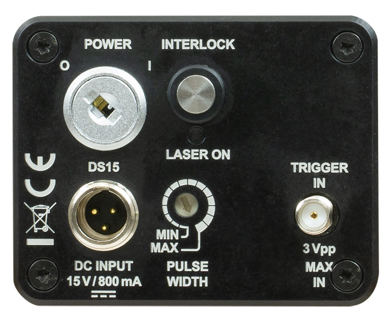
Click to Enlarge
Back Panel (See the Back Panels Tab for Additional Information)
- User-Adjustable Pulse Width (See Table Below)
- Generate Pulses with a User-Supplied Trigger
- Trigger Signal Input via SMA Connector on Back Panel
- 50 kHz Max Repetition Rate
These nanosecond pulsed laser systems output adjustable-duration nanosecond pulses in response to a user-supplied trigger input sent to the Trigger In port on the back panel of the laser head, shown in the image on the right. They provide higher pulse energy than lasers with Item #s ending in A or B. Pulses may be triggered at rates up to 50 kHz. The aspheric lens integrated into the laser head is permanently fixed and factory set to collimate the optical output.
Pulse widths are adjustable from 6 to 129 ns over 16 discrete settings with approximately equal spacing. Plots of typical pulses are located in the table below. The control for adjusting the pulse width is located on the back panel. The included 2.5 mm flathead screwdriver can be used to change the pulse width setting.
Please see the Back Panels tab and manual for more information about the features on the back panel.
These laser systems include the laser head, a +15 V power supply, a 2.5 mm flathead screwdriver, and two ECM225 clamps for post mounting the laser head. Please see the Shipping List tab for a complete list of included components.
| Key Specificationsa | |||||||||
|---|---|---|---|---|---|---|---|---|---|
| Item # | Center Wavelength (Typ.) |
Output Spectrum (Typ.) |
Pulse Width |
Typical Pulses |
Pulse Energy (Typ. Max)b |
Peak Power (Typ. Max)c |
Average Power (Max)b |
External Trigger Frequency (Max)d |
Internal Trigger |
| NPL41C | 405 ± 10 nm |  |
6 to 129 ns |  |
128 nJ | 1000 mW | 6.4 mW | 50 kHz | No |
| NPL45C | 450 ± 10 nm |  |
 |
204 nJ | 1600 mW | 10.2 mW | |||
| NPL52C | 520 ± 10 nm |  |
 |
186 nJ | 1500 mW | 9.3 mW | |||
| NPL64C | 640 ± 10 nm |  |
 |
126 nJ | 1000 mW | 6.3 mW | |||
| NPL81C | 808 ± 10 nm | |
|
186 nJ | 1500 mW | 9.3 mW | |||
| NPL94C | 940 ± 10 nm | |
 |
129 nJ | 1000 mW | 6.5 mW | |||

 Zoom
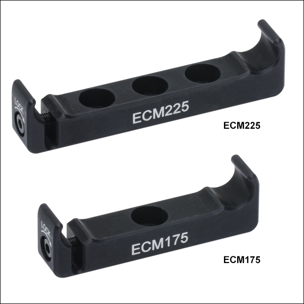
Zoom- Both Clamps Compatible with all NPL Series Laser Housings
- ECM225 Attaches to Bottom or Top of Laser Housing
- ECM175 Attaches to Sides of Laser Housing
Each NPL series Pulsed Laser Diode system includes two ECM225 anodized aluminum clamps, which snap onto the bottom of the laser housing and are secured by tightening the flexure lock using the 2 mm (5/64") hex locking screw. Additional ECM225 clamps, as well as ECM175 clamps that attach to the side of the laser housing, are available separately. The ECM225 and ECM175 are two of Thorlabs' family of aluminum side clamps that are designed to securely mount Thorlabs' rectangular electronics housings.
The ECM225 has three #8 (M4) counterbored through holes, and the ECM175 has one. The counterbored through holes allow the clamps to be mounted on a Ø1/2" post or any surface with an 8-32 (M4) tap. The clamp must be mounted via the counterbored through hole before the electronics housing is attached, as the counterbore will not be accessible once the housing is secured in the clamp.

 Zoom
Zoom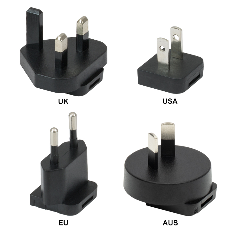
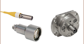
Click for Details
Region-Specific Adapters for DS15
- 15 VDC Regulated Power Supply
- Mini-XLR Connector
- Compatible with Our Nanosecond Pulsed Laser Systems
The DS15 is a 15 V regulated power supply with a 1.53 m (60.24") long cable and a Mini-XLR connector. It is suitable for any Mini-XLR-compatible device that requires a 15 VDC output, and is directly compatible with our nanosecond pulsed laser systems, sold above. A region-specific adapter plug is shipped with the DS15 power supply based on your location.