 Products Home
Complete M² Measurement Systems
- Complete M2 Measurement Systems for UV, Visible, and IR Wavelengths
- For CW & Pulsed Sources
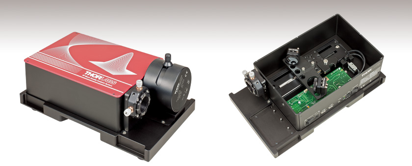
M2MS-BP209IR2
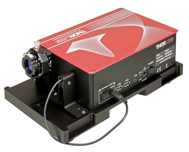
M2 Measurement System with Mounted Scanning-Slit Beam Profiler
The M2 measurement system
uses a retroreflector to change
the position of the beam waist
with respect to the beam profiler.


Please Wait
Click to Enlarge
Figure 1.1 The included alignment laser is shown mounted in place of the beam profiler. Use the beam output from the center of the input aperture to align the test laser source with the axis of the M2 measurement system.
Features
- Self-Contained Systems for Measuring Laser Beam Quality
- Measure Beam Properties Including M2, Divergence, Focus Diameter, Waist Position, and Rayleigh Length
- Two Beam Profiler Options:
- Included Scanning-Slit Beam Profiler
- No Beam Profiler (Includes Mounting Adapters for Scanning Slit and Camera Beam Profilers)
- Systems Cover 250 nm - 2700 nm Wavelengths, See Table 1.5 for Options
- Compliant with ISO 11146 Standards for Beam Quality Measurements
Thorlabs' M2 Measurement Systems provide self-contained, turnkey solutions for measuring M2, divergence, focus diameter, waist position, Rayleigh length, and other laser beam quality metrics. Pre-configured, factory-aligned systems covering wavelength ranges between 250 nm and 2700 nm are available. Choose from among systems that have a scanning-slit beam profiler or no beam profiler. Each system includes a set of lenses, an alignment

Click to Enlarge
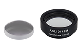
Figure 1.2 Several lenses with AR-coatings optimized for different wavelength ranges are included with each M² measurement system. They are mounted in a quick-release mounting carriage so that they can be easily exchanged.
The M2
Thorlabs' scanning-slit beam profilers are compatible with near-Gaussian beams. Scanning-slit beam profilers acquire power measurements while sampling segments of the beam along two orthogonal axes, and the beam profile is reconstructed from these measurement data. These beam profilers measure pulsed laser beams using an averaging technique.
Click to Enlarge
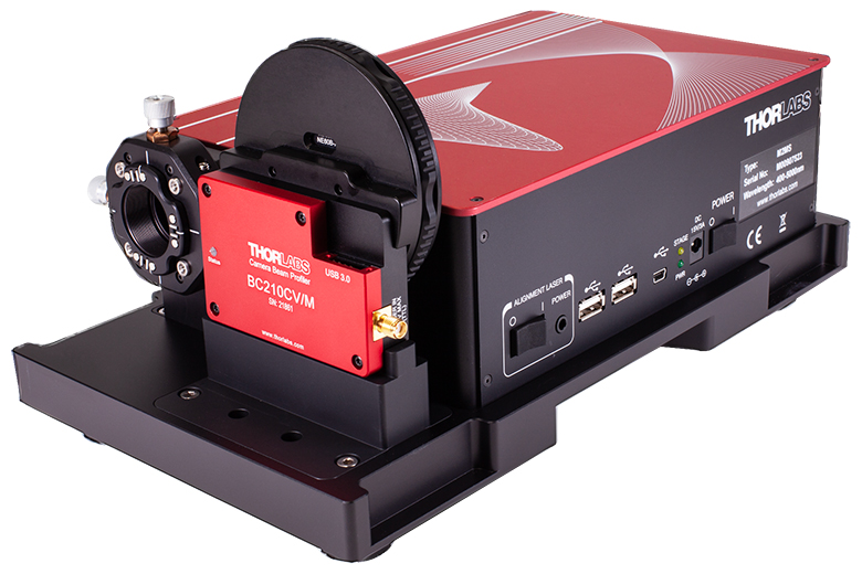
Figure 1.3 An extension set enables one of Thorlabs' camera-based beam profilers to be combined with the M2 measurement system.
Extension Sets for Thorlabs' Beam Profilers
Our extension sets without beam profilers are offered for users interested in adding M2 measurement capability to one or more of Thorlabs' beam profilers that were purchased separately. These extension sets convert any of our BP209 Scanning Slit Beam Profilers, BC207 Series and BC210C Series CMOS Camera Beam Profilers, or previous-generation BP10x Scanning Slit and BC106N CCD Camera Beam Profilers into a fully automated, motorized M2 analysis system. Each extension set includes mounting adapters for the BP209 scanning slit beam profiler and the BC207 and BC210C* series camera beam profilers that raise the input port of the profiler to the height of the beam path through the M² analysis system. To purchase the adapter compatible with the previous-generation BC106N camera profilers, please contact Tech Sales.
*Users who purchased an M2 measurement system extension set before August 5, 2023 and wish to use a BC210C Series Camera Beam Profiler may receive the appropriate adapter by contacting Tech Sales.
M2 Measurement Technique
The M2 measurement system acquires measurements while translating mirrors inside of the enclosure vary the beam path length. The focusing lens and the beam profiler, which is mounted to the front of the enclosure, remain stationary during operation. The two moving mirrors form a retroreflector, and they are mounted on a translation stage. The mirrors in the M2MS-based systems are optimized for 400 nm - 2700 nm wavelengths, while those in the M2MS-
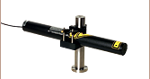
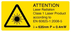 Figure 1.4 Each extension kit ships with a Class 1 alignment laser.
Alignment Laser and Other Included Accessories
Each system includes a set of lenses with 250 mm focal lengths, an alignment laser, and additional accessories. The lens set included with the M2MS-based systems cover wavelengths between 350 nm and 3000 nm, and those included with the M2MS-
*The CXY1Q XY translating mount is a previous generation item no longer available for individual sale.
Beam Software and Programming Guides
The M2 measurement systems are controlled via the Thorlabs Beam software package, which is also used to control our beam profilers, enabling accurate measurements of a variety of beam-related parameters. Please see the User Interface tab for an introduction to the software's capabilities and GUI, and the manuals for the system of interest for a detailed discussion. The software can be downloaded from the Software tab, as well as programming reference guides for LabVIEW™, C, Visual C#, and Python.
Housing Features
The side of the M² measurement system features ports for various peripherals. Two USB 2.0 (type A) hubs are provided and can be used to connect to the slit beam profiler and one other device such as the TSP01 USB temperature and humidity sensor. The phono jack supplies power to the alignment laser, and the mini-B USB port is used to connect to the controlling PC. The translation stage inside of the system also communicates with the computer through this port.
The housing of the M2 measurement system rests on four feet at the corners created by a 0.5 mm deep relief cut in the base. A set of RDF1 rubber damping feet are included. Five M6 x 1.0 mm taps allow for the installation of four feet with one near each corner or in a configuration using three feet. Four CL6 table clamps are also provided to secure the system to an optical table.
| Table 1.5 Specifications | |||||||
|---|---|---|---|---|---|---|---|
| Item #a | M2 System Wavelength Range |
Included Beam Profiler | Mirrorsb | Wavelength Range Covered by Lensesc |
|||
| Type | Wavelength Range | Item # | Type | Wavelength Range | |||
| M2MS-AL | 250 - 600 nmd | Nonee | Aluminum | 250 - 600 nm | 245 - 700 nm | ||
| M2MS | 400 - 2700 nmd | Protected Silver | 400 - 2700 nm | 350 - 3000 nm | |||
| M2MS-BP209VIS-AL(/M) | 250 - 600 nm | Scanning Slit | 200 - 1100 nm | BP209-VIS(/M) | Aluminum | 250 - 600 nm | 245 - 700 nm |
| M2MS-BP209VIS(/M) | 400 - 1100 nm | Protected Silver | 400 - 2700 nm | 350 - 3000 nm | |||
| M2MSBP2I(/M) | 500 - 1700 nm | 500 - 1700 nm | BP209IR1(/M) |
Protected Silver | 400 - 2700 nm | 350 - 3000 nm | |
| M2MS-BP209IR2(/M) | 900 - 2700 nm | 900 - 2700 nm | BP209-IR2(/M) | Protected Silver | 400 - 2700 nm | 350 - 3000 nm | |
M² Analysis Systems with a Dual Scanning-Slit Beam Profiler
| Table 2.1 Specifications | ||||||
|---|---|---|---|---|---|---|
| Item # | M2MS-BP209VIS-AL(/M) | M2MS-BP209-VIS(/M) | M2MSBP2I(/M) | M2MS-BP209IR2(/M) | ||
| Beam Profiler Item # | BP209-VIS(/M) | BP209IR1(/M) | BP209-IR2(/M) | |||
| System Wavelength Range | 250 - 600 nm | 400 - 1100 nm | 500 - 1700 nm | 900 - 2700 nm | ||
| Beam Diameter Range | 20 µm - 9 mm (at Beam Profiler Input Aperture)a | |||||
| Power Range | 1 µW to 10 W (Depending on Beam Diameter; See Figure 2.2) | |||||
| Internal Translation Stage | Travel Range | 100 mm | ||||
| Velocity (Max) | 500 mm/s | |||||
| Effective Translation Range | 200 mm, -100 mm to +100 mm from Focal Point | |||||
| Lens Focal Length | 250 mm | |||||
| Optical Axis Height | 70 mm (Without Additional Feet) | |||||
| M² Measurement Range | ≥1.0 (No Upper Limit) | |||||
| Typical M² Accuracy | ±5%, Depending on Optics and Alignment | |||||
| Accepted Beam Diameter for 5% Uncertainty | 20 µm - 4.5 mm (at Beam Profiler Input Aperture) | |||||
| Minimum Detectable Divergence Angle | <0.1 mrad | |||||
| Applicable Light Sources | CW and Pulsed Sources ≥300 kHz | |||||
| Typical Measurement Time | 15 - 30 s (Depending on Beam Shape and Settings) | |||||
| General Specifications | ||||||
| Size | 300.0 mm x 175.0 mm x 129.7 mm (11.81" x 6.89" x 5.10") | |||||
| Mass (Weight) | 4.6 kg (10.1 lbs) | |||||
Click to Enlarge
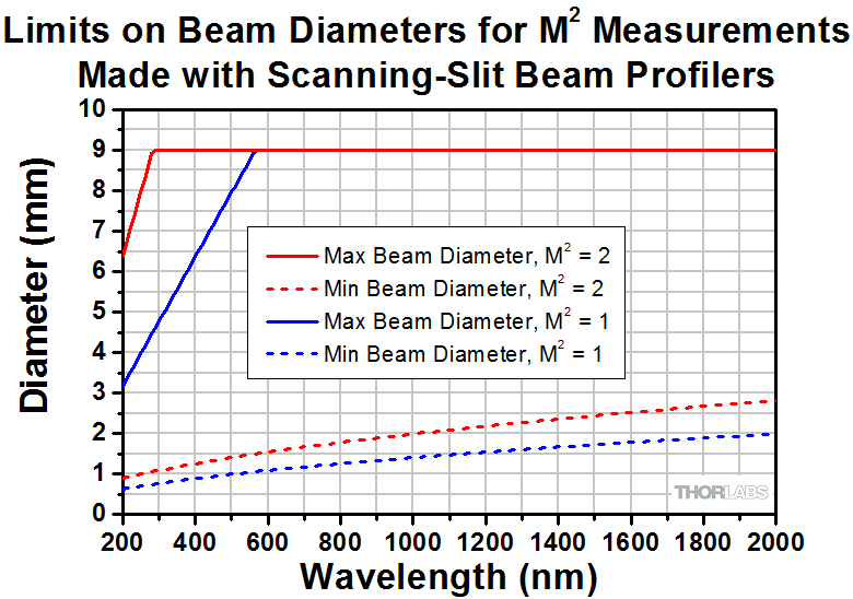
Figure 2.2 The range of beam diameters at the input lens that can be analyzed by the M² measurement systems for two cases: M² = 1 and M² = 2 are limited by the wavelength-dependent bounds plotted above. These limitations apply only to measurements of M² and related parameters, such as the Rayleigh length. For other measurements, such as standard beam analysis or divergence measurements, the standard beam diameter ranges given in Table 2.1 apply.

Click to Enlarge
Figure 2.3 These maximum and minimum beam power limits are provided as functions of 1/e2 beam diameter for knife-edge and scanning-slit measurements and may not apply to measurements of total power. Please see the scanning-slit beam profiler page for more information. To prevent thermal damage to the measurement head, do not operate for longer than 5 s with input powers exceeding 1 W.
M² Analysis Systems without an Included Beam Profiler
| Table 2.4 Specifications | |||
|---|---|---|---|
| Item # | M2MS-AL | M2MS | |
| Wavelength Range | 250 - 600 nma | 400 - 2700 nma | |
| Beam Profiler Compatibility | Scanning Slit Beam Profilers: BP209 and Previous-Generation BP10x Camera Beam Profilers: BC207, BC210C, and Previous-Generation BC106b |
||
| Internal Translation Stage | Travel Range | 100 mm | |
| Velocity (Max) | 500 mm/s | ||
| Effective Translation Range | 200 mm, -100 mm to 100 mm from Focal Point | ||
| Lens Focal Length | 250 mm | ||
| Optical Axis Height | 70 mm (Without RDF1 Feet Installed) | ||
| M² Measurement Range | ≥1.0 (No Upper Limit) | ||
| Typical M² Accuracy | ±5% (Depending on Optics and Alignment) | ||
| Minimum Detectable Divergence Angle | <0.1 mrad | ||
| Applicable Light Sources | CW, Pulseda | ||
| Typical Measurement Time | 15 - 30 s (Depending on Beam Shape and Settings) | ||
| General Specifications | |||
| Size | 300 mm x 175 mm x 109 mm (Without Beam Profiler) | ||
| Weight | 4.2 kg | ||
| Item # | Beam Profiler | Beam Profiler Adapters | Included Lensesa | Other Included Accessories |
|---|---|---|---|---|
| M2MS-AL | None | Adapters for BC207 Camera, BC210Cb Camera, and BP209 Slit Beam Profilers |
Lenses with f = 250 mm Mounted in CXY1QF Quick Release Carriage: LA4158-UV (AR Coated for 245 - 400 nm) LA1461-A (AR Coated for 350 - 700 nm) |
Alignment Laser USB 2.0 to Mini B Cable, 3 m USB 2.0 to Mini B (Angled), 0.5 m 15 V, 3.0 A Power Supplyc 0.05" Hex Key 3 mm Balldriver CL6 Table Clamps (Qty. 4) M4 x 0.7 mm Cap Screwsd (Qty. 6) |
| M2MS | Lenses with f = 250 mm Mounted in CXY1QF Quick Release Carriage: LA1461-A (AR Coated for 350 - 700 nm) LA1461-B (AR Coated for 650 - 1050 nm) LA1461-C (AR Coated for 1050 - 1700 nm) LA5255-D (AR Coated for 1650 - 3000 nm) |
|||
| M2MS-BP209VIS-AL(/M) | BP209-VIS(/M) | Beam Profiler is Pre-Installed | Lenses with f = 250 mm Mounted in CXY1QF Quick Release Carriage: LA4158-UV (AR Coated for 245 - 400 nm) LA1461-A (AR Coated for 350 - 700 nm) |
|
| M2MS-BP209VIS(/M) | BP209-VIS(/M) | Lenses with f = 250 mm Mounted in CXY1QF Quick Release Carriage: LA1461-A (AR Coated for 350 - 700 nm) LA1461-B (AR Coated for 650 - 1050 nm) LA1461-C (AR Coated for 1050 - 1700 nm) LA5255-D (AR Coated for 1650 - 3000 nm) |
||
| M2MSBP2I(/M) | BP209IR1(/M) | |||
| M2MS-BP209IR2(/M) | BP209-IR2(/M) |
Main Window
Click to Enlarge
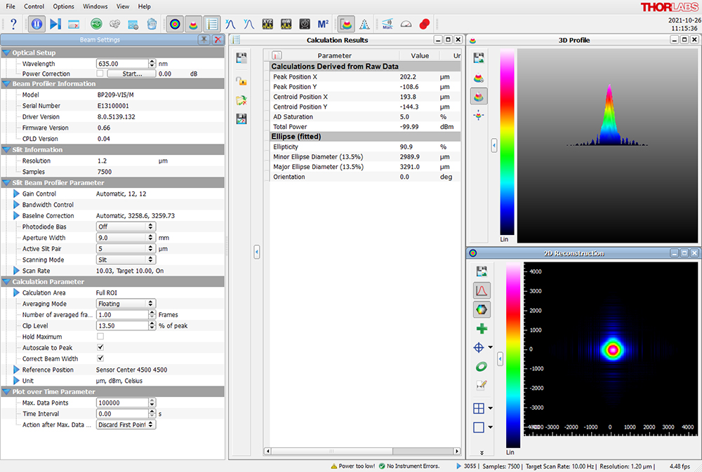
Figure 4.1 The main window of the GUI includes the menu bar, tool bar, status bar, and a frame where several windows can be displayed. This screenshot shows several panels: Beam Settings, Calculation Results, 2D Reconstruction, and 3D Profile. The Beam Settings Panel displays all important information in a single location; this panel can be unpinned from the main window and moved to a second location, such as another monitor. This screenshot shows an application with BP209-VIS/M Dual Scanning-Slit Beam Profiler.
Thorlabs Beam Software for Thorlabs' M² Measurement Systems
- GUI with Adjustable Layout: Windows with Different Measurement Results
can be Rearranged and Resized within the Workspace - M² and Divergence Measurements Compliant with ISO 11146
- Data Export:
- Results can be Exported from Windows in Different Formats
- Sequential Saving of Long Term Test Data
- Pass/Fail Tests with Customizable, Lockable and Saveable Pass/Fail Parameters
- 2D and 3D Views of the Beam Profile
- Selectable Overlays such as Peak, Centroid, and Cut Profiles
- 3D View is Fully Rotatable
- Power Correction Available for Absolute Power Measurements
- Supports TSP01 for Temperature Logging During Long-Term Measurements
Thorlabs' M² Measurement Systems, Scanning Slit Beam Profilers, and Camera Beam Profilers all use the Thorlabs Beam software package. Figures 4.1 through 4.8 highlight key features and measurement modes that can be used with our M² Measurement systems, including M² and divergence measurements, 2D views of the beam profile, and measurement of the beam stability and position.
The latest version of the Beam package can be downloaded from the Software tab.
M2 Measurements
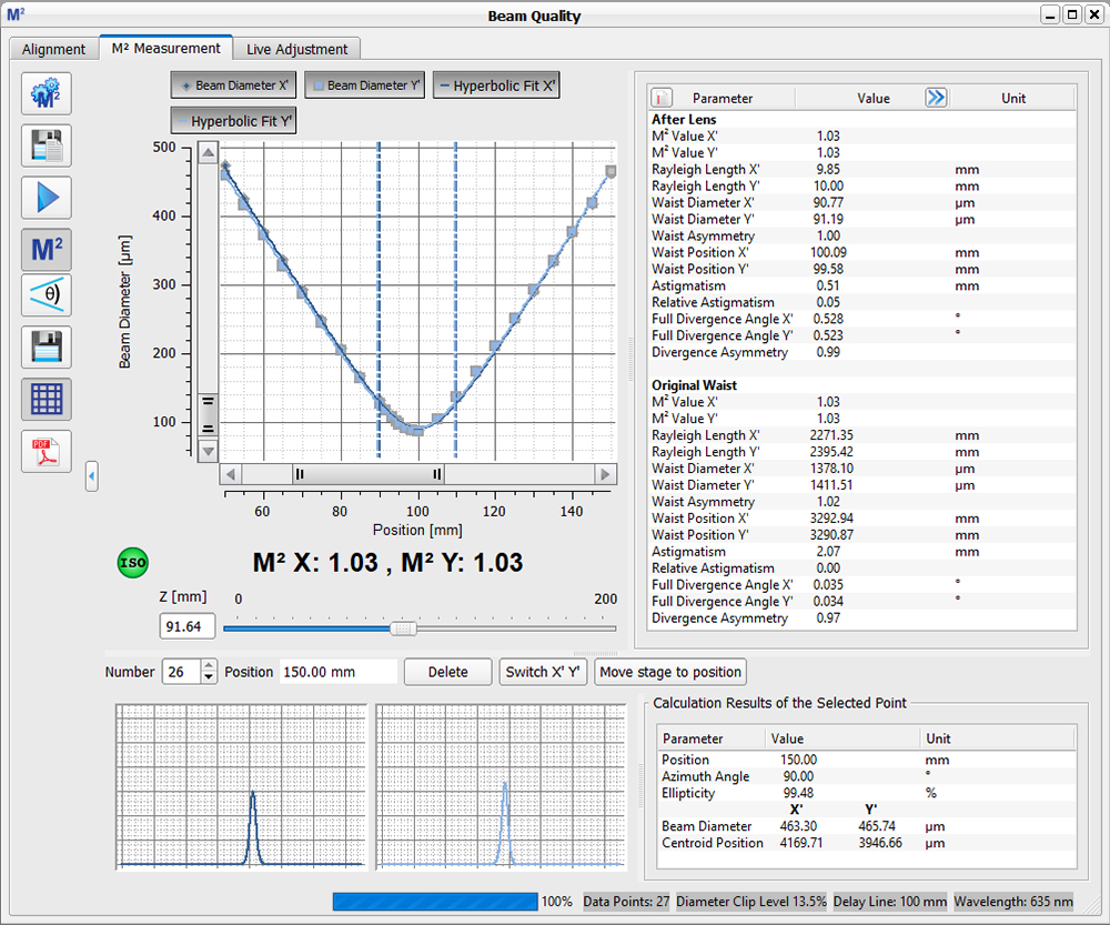
Click to Enlarge
Figure 4.2 The beam diameter and location of the beam waist are shown after an M² analysis has been performed using BP209-VIS/M Dual Scanning-Slit Beam Profiler. Note: This functionality is only enabled when using a beam profiler with one of the M² systems.
Divergence Measurements

Click to Enlarge
Figure 4.3 The divergence of the beam is shown after an M² analysis has been performed using BP209-VIS/M Dual Scanning-Slit Beam Profiler. Note: This functionality is only enabled when using a beam profiler with one of the M² systems.
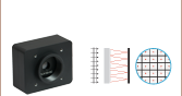
2D Projection (Camera Beam Profilers Only)
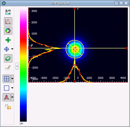
Click to Enlarge
Figure 4.4 The 2D Projection graph shows the image from the Beam Profiler indicating the power intensity distribution within the selected Region of Interest (ROI). Buttons along the side allow users to save the image, show or hide the x and y scales, mark the centroid or peak positions, and display an approximated Beam Ellipse superimposed on the image.
2D Reconstruction (Scanning Slit Beam Profilers Only)
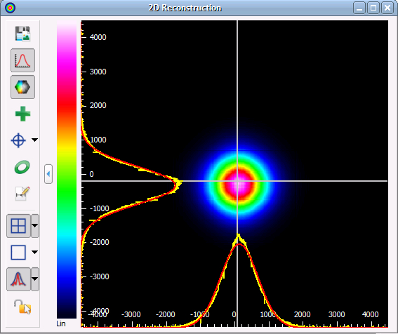
Click to Enlarge
Figure 4.5 Slit beam profilers only measure two real orthogonal cross sections of the beam (i.e., the beam profile in X and Y). Assuming a Gaussian-like beam profile, the Beam software package can create a 2D reconstruction of the beam profile from the two cross sections, seen in the screenshot above. Buttons along the side allow users to save the image, show or hide the x and y scales, mark the centroid or peak position, and display an approximated Beam Ellipse superimposed on the image.
Calculation Results

Beam Stability

Click to Enlarge
Figure 4.7 The Beam Stability Window allows the stability versus time to be recorded and viewed. Display options include the Centroid Positions, Latest Plotted Centroid, Rolling Centroid Positions, Reference Positions, and Smallest Enclosing Circle.
Plot Centroid and Peak Positions
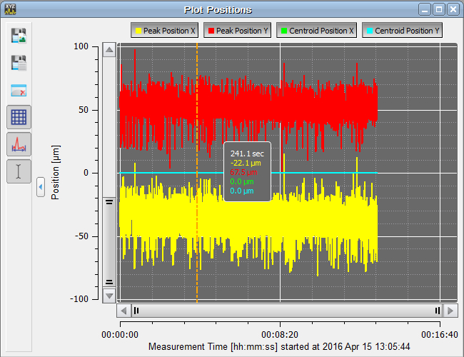
Click to Enlarge
Figure 4.8 The positions of the X and Y peak and X and Y centroid positions can be displayed as a function of time in this window.
Software Packages for Thorlabs' Beam Profilers
The Beam software package can be downloaded by clicking on the Software button below. Please refer to the manual's programming references for interfacing with our beam profilers using LabVIEW™, C, Visual C#, and Python.
Note that the BP209 Scanning Slit Beam Profilers and BC207 Camera Beam Profilers are compatible with version 8.0 or higher of the Beam software, while the BC210C Camera Beam Profilers must be operated using version 9.0 or higher.
| System Requirements | ||
|---|---|---|
| Operating System | Windows® 8.1 (32 Bit or 64 Bit), 10 (32 Bit or 64 Bit), or 11 (for Beam Version 9.0 or Higher) |
|
| Connectivity | Scanning-Slit | USB 2.0 High Speed Port |
| Camera | USB 3.0 High Speed Port | |
| Monitor Resolution | 1024 x 758 Pixel (Min), ≥16 Bit Color Depth | |
| Processor (CPU) | Minimum | ≥3.0 GHz Intel Core (i5 or Higher)a |
| Recommended | Intel Core 2 i5 or AMD Ryzen 5 (3.0 GHz Min) | |
| Memory (RAM) | Minimum | 4.0 GB RAM |
| Recommended | 8.0 GB RAM | |
| Graphics Adapter | Required | OpenGL (Specification GLX 1.3 Up) |
| Minimum | Radeon: X100 Series ≥X850, X1000 Series ≥X1600, HD Series ≥2400; Geforce: 7 Series ≥7600, 8 Series ≥ 8500, 9 Series ≥9600; Quadro: FX Series ≥FX770M |
|
| Recommended | Radeon: HD Series ≥7000; Geforce: GTX Series ≥500; |
|
| Hard Drive | Minimum | 2 GB of Available Disk Space |
Features
- Settings Panel Displays All Important Parameters in a Central Location
- Customizable Calculation Results
- Measured Parameters can be Individually Hidden
- Adjustable Row Heights
- Enhanced Beam Stability Window Measures and Displays the
Smallest Enclosing Circle Around the Centroid Point Cloud
- Alignment Wizard to Aid in Correctly Aligning the M2MS M2 Measurement Systems
- Language Settings of English, German, or Chinese
Software
Version 9.2.6002.614 (February 12, 2025)
Standard full version of software package for 32-bit and 64-bit Windows with driver and graphical user interface for operating the device in standard applications.

Firmware Update for Scanning Slit Beam Profilers
Below is a link to a firmware update for Thorlabs scanning slit beam profilers to correct an error regarding hardware and firmware compatibility.
Firmware Update
Version 1.6 (April 26, 2024)
Click on the link below to download the latest firmware. The link includes instructions for installing the firmware update.

| Posted Comments: | |
Matěj Ž
(posted 2025-10-16 12:44:19.03) Hello,
we recently bought a M2MS with a BC210 camera and have an issue with the translation stage. It only moves 50 mm (from 50 to 100mm position), although the software sees it travelling normally 0-100mm. This makes any M2 measurent impossible, since we can only see one side of the waist. Can you help us diagnose/solve this problem please? Thank you in advance. hchow
(posted 2025-10-17 03:54:45.0) Dear Matej Z, thank you for your feedback. I will personally contact you to provide assistance. Thank you. Juan Reto Reynal
(posted 2025-05-05 09:32:04.127) Hi! Hope you are doing great! I'd like to suggest to include an InGaAs camera beam profiler to measure both M^2 and far-field divergence on the M2MS systems, there is a whole industry looking for such an off the shelf instrument like this! Thanks for your consideration. hkarpenko
(posted 2025-05-06 06:10:04.0) Dear Juan,
thank you very much for your feedback. We will record your suggestions for future product designs. Aaron R
(posted 2024-07-02 14:15:36.847) Hi, you state that a beam should not have a larger diameter than 4.5mm for a 5% uncertainty. Can you make a statement on the uncertainty of beams >4.5mm diameter? In particular, we will have beams between 4.8 and 6mm. hkarpenko
(posted 2024-07-04 05:26:19.0) Dear customer,
thank you for your feedback.
This statement can be extended to beams up to 6mm. I will contact you directly to discuss this further in detail with you. Clemens Alt
(posted 2024-01-12 11:40:46.173) Good morning,
Question about the wavelength ranges of the M2MSBP2I, specifically about the BP209IR1 and IR2.
The manual shows the spectra for both on page 149. At 500 nm, the IR1 has a responsively of ≈0.2 A/W. The IR2 has a responsively of ≈0.35 A/W at 900 nm.
Is there any way to obtain information on the responsivity of the IR2 below 900 nm? How would the responsivity of the IR2 compare to the IR1 at 500 nm?
Thank you for your help. hchow
(posted 2024-01-16 07:59:36.0) Dear Mr. Alt, thank you for your enquiry. I will reach out to you personally to provide the information you requested. Thank you. Dicky Lee
(posted 2023-12-01 13:08:02.377) Thorlabs team,
We recently purchased an M2MS-BP209IR2 system. Upon removing the contents from the hard-case, we found that all of the contents are covered with small black particles, on the plastic bags, power supply, M2MS accessory box,...
As you can understand, an optical instrument covered with particles is less than acceptable. Fortunately, the particles do not seem to have gotten inside the plastic bags and onto the instrument itself. But I suppose I'll find out when I start using the instrument.
I would expect better QA from Thorlabs. I took pictures that I can share if it helps understanding the origin of the contamination. dpossin
(posted 2023-12-04 04:18:11.0) Dear Dicky,
Thank you for your inquiry and sorry for the experience you´ve had. I´ll reach out to you in order to discuss this in more detail and execute suitable steps. Yicheng Lai
(posted 2023-08-16 11:03:22.007) Dear sir
Can you help advise what will be the maximum measurable divergence for M2MS-BP209VIS(/M)?
Is this limited by the 200mm translation range?
And are there other focal length lens options available?
thx
yicheng dpossin
(posted 2023-08-21 08:53:34.0) Dear Yicheng,
Thank you for your feedback. The max divergence angle is limited by the aperture size of the BP209 and the translation range of the M2MS. It can be tracked down via simple trigonometrical considerations. Given that tr means the translation range, D means the aperture size, theta means the divergence angle, d means the input beam diameter and L means the distance between the laser source and the beam profiler, the divergence angle can be calculated as:
theta=arctan((D-d)/(2*(tr+L)))
I am reaching out to you in order to provide further details. Barry Luther-Davies
(posted 2023-02-02 16:34:40.507) I need to measure M^2 of a parametric amplifier output around 1340nm. The measurement is complicated by the fact that the OPA amplifies a seed beam with is nearly collinear with the main output and contains around 5-10% of the power. In order to measure the M^2 of the main beam thus it is desirable to subtract the seeder beam from the main beam for each position in the M^2 measurement since the seeder has a different size, position and focusing properties from the main beam. Can this be done with your system? Please advise.Thanks Barry hkarpenko
(posted 2023-02-06 10:20:01.0) Dear customer,
thank you very much for your feedback. In case of colinear beams, where both profiles are overlapping, it is not possible to seperate the beam intensities. The beam profiler will always see both beams as one beam. I will contact you directly to discuss this issue further. Grzegorz Zeglinski
(posted 2021-07-02 08:51:27.58) Hi, I have BP104-IR (800-1700nm) number M00245811 and original CD with software for BP v 2.8. CD has applcation software, drivers libraries and manual. I have original printed-manual. Problem any software (V2.8, v.6.0, v6.2, v7) doesn't see driver BP! I read info form manual and form files but it doesn't work. I check it in XP-32 nad win7-64. I wiil be very grateful for help. Some years ago the BP was working. Cabel USB is original. Best Regards Grzegorz ZEglinski MKiess
(posted 2021-07-06 07:49:15.0) Dear Grzegorz, thank you very much for your inquiry. I have contacted you directly to provide further assistance and troubleshooting. Luke Parker
(posted 2021-04-21 13:10:18.443) Want to speak about the technical capabilities of this measurement system and training on use. Want to ensure this is the correct setup for measuring the welding beams at our plant prior to ordering. Also interested in discussing options for temporal beam profiling. soswald
(posted 2021-04-23 10:57:35.0) Dear Luke,
thank you for your feedback. I have contacted you directly to discuss your application in more detail. user
(posted 2021-03-03 20:37:55.623) The documentation related to this M^2 measurement system was AMAZING! I just wanted to give kudos to whoever wrote it. There are sections in there that are better and more useful than many white papers I have read.
No questions here, just please let the author know they did a great job. MKiess
(posted 2021-03-05 06:51:34.0) Thank you very much for this feedback. We are glad to hear that you are satisfied with the documentation of the M^2 system and that you like the comprehensiveness of the descriptions. Alexander Radnaev
(posted 2020-10-27 09:57:13.607) Hello, when can we expect Python API for the wonderful M^2 measurement system and the beam profilers?
Python is one of the most modern, useful, convenient, ubiquitous programming languages - would be great for your devices to support it. https://www.northeastern.edu/graduate/blog/most-popular-programming-languages/
Thanks! MKiess
(posted 2020-10-28 10:33:46.0) Dear Alexander, thank you very much for the feedback. Unfortunately, there is no driver available for the complete M2 system at the moment.
In general it is possible to program the optical delay line within the M2 system and the Beam Profiler individually. This means that the combination of optical delay line and Beam Profiler is possible, but there are no commands available e.g. for measuring the divergence or the M2 value.
These would have to be programmed by the user. Alexander Radnaev
(posted 2020-09-03 09:44:38.713) Overall pretty good product, but there is one big gap in the software data analysis: while it supports Gaussian fit for a given profile, there is no way to use beam diameter extracted from Gaussian fit to be used in the actual M^2 scan and measurement based response from the technical support.
It's a big problem because available 4 sigma method (the ISO deterministic second moment statistic) and clip (find 13.5% level datapoint) methods can be vastly wrong (by a factor of 2x, 100% error) - because they either too sensitive to noise or structure of the beam. I've spent hours with technical support just to get an answer that the software down't support Gaussian fit for M^2 scan measurement (see CAS-291612-F7M0B8 case).
My wish Thorlabs invests into adding option "beam diameter from Gaussian fit" into the "Beam Quality Settings -> Beam Width for M^2 Measurement" in addition to the 5 options (see page 121 https://www.thorlabs.com/_sd.cfm?fileName=MTN003822-D02.pdf&partNumber=M2MS-BC106VIS) dpossin
(posted 2020-09-07 07:38:59.0) Dear Alexander,
Thank you for your feedback. I will discuss this with our development engineers and reach out to you via mail. user
(posted 2020-07-21 21:23:59.38) Hi, I have two M^2 systems, and would like to know the reference plane for the two systems. Also, doe the thorlabs software account for chromatic shift of the ideal focus when changing the wavelengh? dpossin
(posted 2020-07-27 05:59:41.0) Dear Customer,
Thank you for your feedback. The distance between the plane of the beamprofiler and the reference plane of the M2 system is measured during manufacturing and can be found out with the serial number. Typically the distance is about 126mm.
It is not needed to know the exact focal lenght in order to determine the M2 value. All you need is the divergence angle, the beam waist and the wavelength but there is no chromatic aberration correction.
I am reaching out to you in order to provide further information. user
(posted 2020-03-07 18:30:17.113) While using your BC106NVIS/M meter, I have two questions:
1) Do the hyperbolic fit parameters correspond to the beam focused by the lens or to the tested beam?
2) What is the reference plane (Z=0) for the "Beam waist position" parameter?
Thanks in advance. nreusch
(posted 2020-03-09 08:12:39.0) This is a response from Nicola at Thorlabs. Thank you very much for your inquiry. The hyperbolic fit parameter corresponds to the focused beam. You can derive the respective values of the tested unfocused beam before the lens. We are currently working on a software solution that will make it more convenient to retrieve these data. I will contact you directly to discuss the calculation of the parameters before the lens and send you a drawing that shows the position of the reference plane. buk
(posted 2017-08-16 13:45:08.627) Hi, I need to characterise lasers from 355 nm to 2um. The M2MS-BC106VIS/M indicated the mirrors are able to reflect well only above 400 nm. So at 355 nm the model I am choosing can still measure the UV laser beam for the M2 system? mvonsivers
(posted 2017-08-17 04:59:53.0) This is a response from Moritz at Thorlabs. Thank you for your inquiry. The mirrors have a protected silver coating and you can find a typical reflectance plot in the link below.
https://www.thorlabs.com/newgrouppage9.cfm?objectgroup_id=903
At 355 nm the reflectance is typically about 80% but it is falling off steeply. Due to variations between different coating runs the reflectance could also be significantly lower. Also please note that the beam profiler is only sensitive up to a wavelength of 1100 nm. We will contact you directly to discuss alternative options. marcus.roeppischer
(posted 2017-02-14 02:04:05.767) Is it possible to use the product for collimated Laser to measure the divegence angle? tcampbell
(posted 2017-02-14 08:53:23.0) Response from Tim at Thorlabs: thank you for your feedback. Yes, these systems can be used to measure the divergence of a beam. Details on beam divergence measurement can be found in the manual for each beam profiler. david.szwer
(posted 2015-09-23 11:56:19.11) To follow up Amanda's question, I use the M2MS without a lens, to profile a converging beam. It would be helpful to be able to relate the z-position of the waist to a physical position - e.g. adding a number to get the distance from the front edge of the M2MS's baseplate. That would be a helpful addition to the manual. shallwig
(posted 2015-09-24 06:06:56.0) This is a response from Stefan at Thorlabs. Thank you very much for your feedback . I discussed your inquiry with the responsible engineer and we will implement these information about the distances in future software versions. These distances are not the same for all devices. So far we can provide the distances for your specific M2MS Set when knowing which beam profiler model you are using and the serial number of the M2MS Kit. I will contact you directly to discuss this in more detail. amanda
(posted 2015-07-01 15:16:20.09) This product would be more useful if the manual was easier to read. For example, you should not have "unpack your box and check to make sure everything is there" on the 80th page. It should be in the front. The manual is hard to understand and frequently jumps around (is not easy to track). There needs to be a more sequential ordering to the pages. Additionally, some of the product information described on the website should also be included in the manual so that the reader does not have to keep running over to the computer, then back to the manual. Other than that, seems like a cool piece of equipment. shallwig
(posted 2015-07-03 03:04:50.0) This is a response from Stefan at Thorlabs. Thank you very much for your feedback, we are always thankful for any suggestions to make our documentations better understandable and more clear.
Currently we are working on a new manual and this is supposed to be more clear in its texture. I will contact you directly to check which information from the Web you are missing in the manual and to discuss if there are any further questions I can help with. |
Please build your system below:

1. Beam Profiler
M2 Measurement Systems can be configured with scanning-slit beam profilers optimized for UV, visible, or NIR wavelengths. Systems may also be configured without a beam profiler for use as an extension set to add M2 measurement capability to a separately purchased beam profiler. See above for a list of compatible beam profilers.
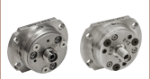
2. Mirrors
Along with the beam profiler, the choice of mirrors will set the wavelength range of your configured system.