 Products Home
Multimode Fiber Optic Filter/Attenuator Mounts
- Reflective, Achromatic Design for 250 nm - 450 nm or 450 nm - 20 µm
- Mount Filters, Cuvettes, or Variable Attenuator in the Optical Path
- Ideal for Ø200 µm to Ø1000 µm Core Multimode Fibers with ≤0.39 NA
- Models with FC/PC or SMA Connectors
CFH2-B
Blank Insert
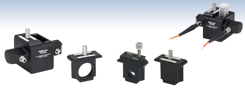
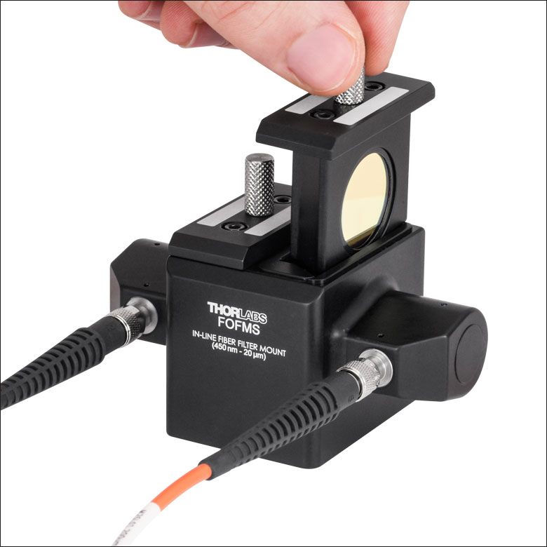
FOFMS
SMA Connectors,
Shown with One Filter
Holder Removed
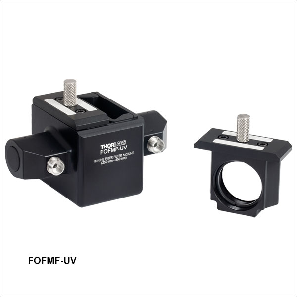
Two SM1-Threaded (1.035"-40) Filter Holders are Included with Each Mount
Application Idea
Each filter holder can be replaced with a macro or micro cuvette, making the in-line fiber filter mounts ideal for absorption spectroscopy. See the Application tab for details.
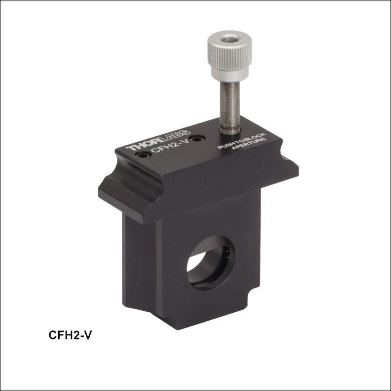
CFH2-V
Variable Attenuator Insert


Please Wait
Click for Details
Diagram of the Beam Path Through the In-Line Fiber Filter Mount

Features
- Free-Space, Fiber-to-Fiber Coupling System Utilizing Off-Axis Parabolic (OAP) Mirrors
- UV-Enhanced Aluminum Coating (250 nm - 450 nm) for UV Sources
- Protected Silver Coating (450 nm - 20 µm) for Broadband Sources
- FC/PC or SMA Connectors
- Mounts with Item # Prefix FOFMF Accept Both 2.2 mm Wide Key and 2.0 mm Narrow Key Connectors
- Mounts with Item # Prefix FOFMS Accept SMA905 Connectors
- Two CFH2-F Ø1" Filter Holders Included With Each Mount
- Compatible with Macro and Micro Cuvettes (Not Included, See Specs Tab for Details)
- Bottom-Located 1/4"-20 (M6) Tap for Mounting to a Post or any Mounting Base
- Accessories Available Separately Below
- Replacement Filter Holder Insert
- Blank Insert
- Variable Attenuator Insert
- Light-Tight Cover
Thorlabs' In-Line Fiber Optic Filter Mounts are ideal for fiber-based applications that require light to be spectrally filtered or reduced in intensity. As shown in the diagram to the right, each mount is composed of two removable CFH2-F filter holders within a fixed, free-space fiber-to-fiber coupling system. The system utilizes two off-axis parabolic (OAP) mirrors to collimate the light out of the input fiber and couple it into the output fiber. The use of these mirrors provides high reflectance, high NA, and achromatic performance over the reflection band. For more information about the OAP mirrors, please see the Specs tab. The all-reflective design eliminates phase delays and absorption losses introduced by transmissive optics.
Either filter holder can be replaced with a 12.5 mm x 12.5 mm synthetic quartz glass cuvette (not included), making these mounts ideal for use in absorption or transmission spectroscopy measurements (see the Application tab for details). The system is light tight when two filter holders are used or with the use of the FOFM-CV light-tight cover.
For custom fiber bulkheads, mirror coatings, or filter holders, please contact Tech Support.
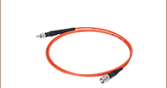
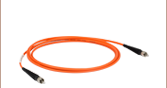
Fiber Compatibility
Thorlabs' In-Line Fiber Optic Filter Mounts are designed to work with multimode patch cables. In general, the mounts cannot be used with single-mode fibers because significant losses are incurred when light is coupled to the narrow core of these fibers in the absence of precision alignment. However, a single mode fiber can be used as the input of the mount provided that the output is connected to a multimode fiber.
Filter Holders, Blank Plates, and Variable Attenuation Insert
Each SM1-threaded (1.035"-40) filter holder can be used to mount various Ø1" filters up to 0.31" (8.0 mm) thick. The precision, spring-loaded, dovetail design of the removable holders ensures reproducible positioning. Two laser-engraved boxes on top of each holder are used for labeling and identification of the mounted optic. Additionally, Ø1/2" filters can be mounted using the SM1A6T Thread Adapter. Extra filter holders are sold separately below.
If the included filter holder does not suit your application, the CFH2-B Blank Plate is also available separately below. This plate uses the same mounting method as the included CFH2-F and can be machined to suit your specific requirements. Alternatively, it can also be used as a manual shutter. The CFH2-V Variable Attenuation Insert can be inserted in place of one of the filter holders to partially or completely block light from passing. It features an adjuster capable of ±0.01 dB attenuation resolution (when used with Ø200 - Ø1000 µm Core, 0.22 - 0.50 NA fiber) along with the ability to quickly block the aperture via a quick-release mechanism.
Light-Tight Cover
A light-tight cover for the fiber optic filter mounts is available for applications that are particularly sensitive to light. This cover is compatible with cuvettes up to 50 mm (1.96") tall, including the stopper. Please note that the FOFM-CV cover is not compatible with the CFH2-V attenuator insert.
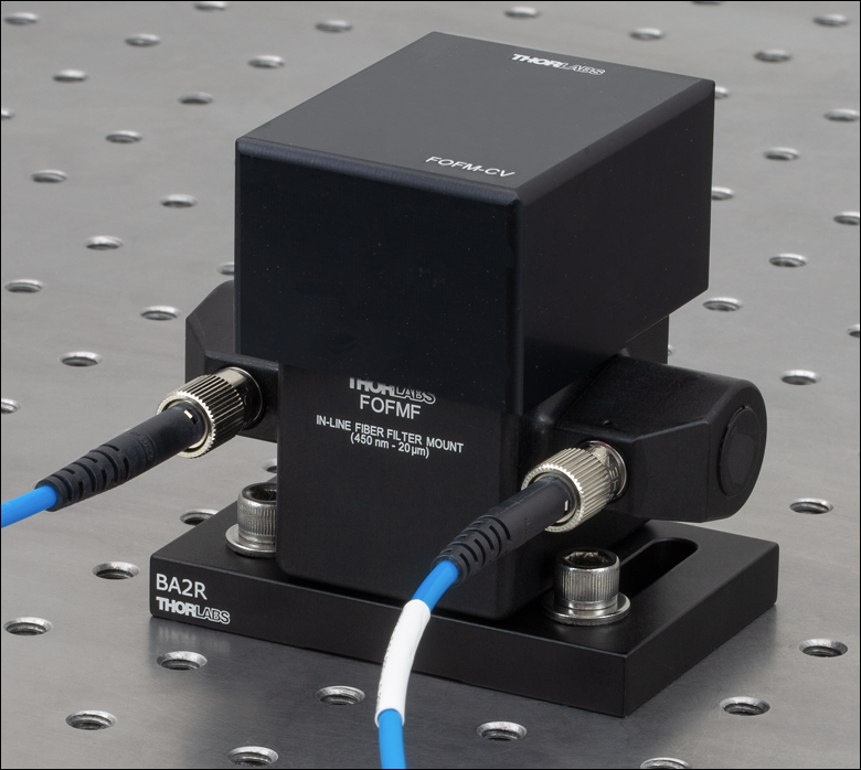
Mounting Options
A bottom-located 1/4"-20 (M6) tap is used to mount the in-line fiber filter mounts onto a Ø1/2" post or post holder base, such as the BA2R Magnetic Base (shown in the image above) or UBP2 Universal Base.
We also offer cuvette holders for applications such as free-space fluorescence measurements.
| Item # | FOFMF(/M)-UV | FOFMS(/M)-UV | FOFMF(/M) | FOFMS(/M) | |||
|---|---|---|---|---|---|---|---|
| Compatible Connectors | FC/PCa | SMA905 | FC/PCa | SMA905 | |||
| Recommended Input NAb | ≤0.39 NA | ||||||
| Insertion Lossc (No Filters or Cuvettes) |
<3.5 dB @ 250 - 350 nmd <2.0 dB @ 350 - 450 nmd |
≤2 dB @ 450 nm - 20 µme | |||||
| Filter Holders | Two Included (CFH2-F) | ||||||
| Compatible Filter Dimensions | Ø1" (25.4 mm), 0.31" (8.0 mm) Thick |
||||||
| Compatible Cuvette Dimensionsf | 12.5 mm x 12.5 mm (0.49" x 0.49") |
||||||
| Mount Dimensions (Excluding Filter Holder) | 2.00" x 3.31" x 1.60" (50.8 mm x 84.0 mm x 40.6 mm) |
||||||
| Mount Dimensions (Including Filter Holder) | 2.00" x 3.31" x 2.28" (50.8 mm x 84.0 mm x 57.9 mm) |
||||||
| Tap | 1/4"-20 (M6) | ||||||
| Off-Axis Parabolic Mirror Specificationsg | |||||||
| Item # | MPD00M9-F01 | MPD00M9-P01 | |||||
| Coating | UV-Enhanced Aluminum | Protected Silver | |||||
| Reflectance (Average) Click for Plot |
>90%, 250 - 450 nm | >97%, 450 nm - 2 µm >96%, 2 - 20 µm |
|||||
| Off-Axis Angle | 90° | ||||||
| Reflected Focal Length | 15.0 mm (0.59") | ||||||
| Surface Roughness | <100 Å (RMS) | ||||||
| Reflected Wavefront Error | λ/4 at 633 nm | ||||||
| Surface Quality | 40-20 Scratch-Dig | ||||||
Beam Diameter After Collimation
Click to Enlarge
Diagram of the Beam Path Through the In-Line Fiber Filter Mount
Beam diameter can be calculated very easily using the numerical aperture of the fiber (NA) and the reflected focal length of the OAP. To calculate the beam diameter in the small angle approximation, use the following equation:
Beam Diameter = 2 x NA (Fiber) x Reflected Focal Length
The table below lists the output beam diameter as a function of the reflected focal length of the mirror and the numerical aperture of the fiber. The clear aperture of the OAP should be larger than the desired beam output diameter.
| Fiber NA | Beam Diameter | OAP Clear Aperture | |
|---|---|---|---|
| 0.10 | 3 mm | >Ø11.43 mm | |
| 0.20 | 6 mm | ||
| 0.39 | 11.7 mma | ||
| 0.50 | 12.7 mma | ||
Insertion Loss vs Wavelength
The graphs below compare the insertion loss vs wavelength for different fiber types. The shaded region denotes the specified wavelength range and insertion loss of the in-line fiber filter mount. Insertion loss at any given wavelength is also dependent upon the properties of the fiber used and is measured without filters or cuvettes.
Click to Enlarge
Excel Spreadsheet with Raw Data
The above plot shows the typical insertion loss versus wavelength for the 450 nm - 250 µm wavelength range in-line fiber filter mounts when MIR multimode fiber patch cables are used with a mode-stripped fiber launch. This can then be compared to the performance of a low-OH silica fiber cable and a theoretical lossless fiber. This data was taken using Thorlabs' SLS202L Broadband Light Sourcea and OSA201C and OSA207C Spectrometer.
Click to Enlarge
Excel Spreadsheet with Raw Data
The above plot shows the typical insertion loss versus wavelength for the 250 nm - 450 nm wavelength range in-line fiber filter mount when used with 0.22 NA solarization-resistant patch cables. This data was taken using a broadband light source and CCS200 Spectrometer. Because the data is measured using a spectrometer, the measured insertion loss is similar to that for a mode-stripped fiber launch.
Click to Enlarge
Excel Spreadsheet with Raw Data
The above plot compares the typical insertion loss versus wavelength for the 450 nm - 250 µm wavelength range FOFMS and the 250 nm - 450 nm wavelength range FOFMS-UV. Note that the insertion loss increases rapidly when approaching UV wavelengths for the FOFMS with low OH silica fiber. In comparison, the FOFMS-UV, with solarization-resistant fiber, maintains <3.5 dB down to 250 nm.
Click to Enlarge
Excel Spreadsheet with Raw Data
The above plot shows the typical insertion loss versus wavelength for the in-line fiber filter mount when used with various 0.22 NA silica fiber patch cables. Note that even for the 50 µm core fiber and fiber bundle, the insertion loss is still around 3 dB. This data was taken using Thorlabs' SLS201L Broadband Light Source and CCS200 Spectrometer. Because the data is measured using a spectrometer, the measured insertion loss is similar to that for a mode-stripped fiber launch.
Insertion Loss at Mode-Stripped and Overfilled Launch Conditions
The graphs below compare the performance of fibers used with the in-line filter mount under different launch conditions. A mode-stripped (70/70) fiber launch condition removes cladding modes that are lost in the in-line filter while an overfilled (>100%) fiber launch condition contains all propagating modes. Because measuring the input and output power using a power meter does not allow for discrimination of these mode types, a mode-stripped launch condition is a better measurement of the actual insertion loss of the in-line fiber filter.
Click to Enlarge
Excel Spreadsheet with Raw Data
The above data was taken to show the negative effects of overfilling the input fiber (defined above). In this plot, the pinhole used in the mode-stripped example to the left was removed and the LED output was sent directly into the fiber. The output from the fiber filter holder was then coupled into an S120C Power Meter.
Click to Enlarge
Excel Spreadsheet with Raw Data
The above data was taken using a mode-stripped fiber launch (defined above). To achieve these conditions a pinhole with a diameter 70% of the fiber core was placed after the output of a previous-generation M470F3 Fiber-Coupled LED. The output from the fiber filter holder was then coupled into an S120C Power Meter. This plot shows similar results compared to using a single mode laser source or mandrel wrapping method.
Click to Enlarge
Excel Spreadsheet with Raw Data
The above data was taken to show the negative effects of overfilling the input fiber (defined above). In this plot, the pinhole used in the mode-stripped example to the left was removed and the LED output was sent directly into the fiber. The output from the fiber filter holder was then coupled into an S120VC Power Meter.

Click to Enlarge
Excel Spreadsheet with Raw Data
The above data was taken using a mode-stripped fiber launch (defined above). To achieve these conditions a pinhole with a diameter 70% of the fiber core was placed after the output of an M385F1 Fiber-Coupled LED. The output from the fiber filter holder was then coupled into an S120VC Power Meter. This plot shows similar results compared to using a single mode laser source or mandrel wrapping method.
Absorption Spectroscopy
Absorption spectroscopy is a technique used to characterize the optical properties of a material by measuring the amount of light absorbed by a sample at a given frequency or wavelength. As a broadband light source is sent through a sample, the sample absorbs a fraction of the incident radiation at certain frequencies or wavelengths. These regional decreases in the overall transmission curve describe the material’s unique absorption spectrum. This technique is commonly used in material analysis to gather details about the chemical composition of an unknown substance or the concentration of a molecule in a solution.
Shown to the right is the absorption spectrum of methanol obtained by using Thorlabs' FOFMS In-Line Fiber Optic Filter Mount along with an SLS202L Broadband Light Sourcea, two 0.20 NA, Ø200 µm Core ZrF4 MIR multimode fiber patch cables, and a previous-generation CV10Q3500 3500 µL Capacity Quartz Cuvette. Quartz cuvettes are ideal due to their high transmission from the UV to the MIR spectrum. A similar example of this setup can be seen in the image at the top of the page.
As light enters the FOFMF filter system, it is collimated at the first protected silver OAP with a beam diameter of approximately 6 mm (see the Specs tab for details). It then passes through two slots that house a Ø1" optical filter or cuvette. In this case, we loaded a single cuvette with a sample of methanol. Once through the cuvette, the light is couple into the output fiber using the second protected silver OAP mirror and measured using a Fourier Transform Infrared Spectrometer (FTIR).

Insights into Off-Axis Parabolic Mirrors
Scroll down to read about the unique properties of off-axis parabolic (OAP) mirrors and how to take advantage of them:
- Why a Parabolic Mirror Instead of a Spherical Mirror?
- Benefit of an Off-Axis Parabolic Mirror
- Directionality of OAP-Mirror-Based Reflective Collimators
Click here for more insights into lab practices and equipment.
Why a Parabolic Mirror Instead of a Spherical Mirror?
Click to Enlarge
Figure 2: Spherical mirrors do not reflect all rays in a collimated beam through a single point. A selection of intersections in the focal volume are indicated by black dots.
Click to Enlarge
Figure 1: Parabolic mirrors have a single focal point for all rays in a collimated beam.
Parabolic mirrors perform better than spherical mirrors when collimating light emitted by a point source or focusing a collimated beam.
Focusing Collimated Light
Parabolic mirrors (Figure 1) focus all rays in an incoming, collimated light beam to a diffraction-limited spot. In contrast, concave spherical mirrors (Figure 2) concentrate incoming collimated light into a volume larger than a diffraction-limited spot. The size of the spherical mirror's focal volume can be reduced by decreasing the diameter of the incoming collimated beam.
Collimating Light from a Point Source
A point source emits light in all directions. When this highly divergent light source is placed at the focal point of a parabolic mirror, the output beam is highly collimated. If the point source were ideal, all reflected rays would be perfectly parallel with one another.
When a point source is placed within a spherical mirror's focal volume, the output beam is not as well collimated as the beam provided by a parabolic mirror. Different rays from the point source are not perfectly parallel after reflection from the spherical mirror, but two reflected rays will be more nearly parallel when they reflect from more closely spaced points on the spherical mirror's surface. Consequently, the quality of the collimated beam can be improved by reducing the area of the reflective surface. This is equivalent to limiting the angular range over which the source in the focal volume emits light.
Choosing Between Parabolic and Spherical Mirrors
A parabolic mirror is not always the better choice. Beam diameter, cost constraints, space limitations, and performance requirements of an application all influence selection. Beam diameter is a factor, since the performance of these two mirrors is more similar when the beam diameter is smaller. Parabolic mirrors are more expensive, since their reflective profiles are more difficult to fabricate. Parabolic mirrors are also typically larger. Improved performance may or may not be more important than the difference in cost and physical size.
Date of Last Edit: Dec. 4, 2019
Benefit of an Off-Axis Parabolic Mirror
Click to Enlarge
Figure 4: An off-axis parabolic mirror can be thought of as a section of the larger parabolic shape. Both have the same focal point, but it is more accessible in the case of an OAP mirror.
Click to Enlarge
Figure 3: The focal point of an on-axis parabolic mirror is close to the reflective surface, and typically surrounded by the reflective surface, which makes the focal point difficult to access.
One of the primary benefits of a concave parabolic mirror is its single focal point. All rays travelling parallel to the mirror's axis are reflected through this point. This is useful for a range of purposes, including imaging and manufacturing applications that require focusing laser light to a diffraction limited spot.
There are a few negatives associated using with using conventional parabolic mirrors, which are symmetric around the focal point (Figure 3). One is that the sides of the mirror generally obstruct access to the focus. Another is that when the mirror is used to collimate a divergent light source, the housing of the light source blocks a portion of the collimated beam. In particular, light emitted at small angles with respect to the optical axis of the mirror is typically obstructed.
An off-axis parabolic (OAP) mirror (Figure 4) is one solution to this problem. The reflective surface of this mirror is parabolic in shape, but it is not symmetric around the focal point. The reflective surface of the OAP corresponds to a section of the parent parabola that is shifted away from the focal point. The section chosen depends on the desired angle and / or distance between the focal point and the center of the mirror.
Date of Last Edit: Dec. 4, 2019
Directionality of OAP-Mirror-Based Reflective Collimators
Click to Enlarge
Figure 6: The reflective element of the collimator is an off-axis parabolic mirror. The mirror's substrate is highlighed in red. The shape of the reflective surface is a segment of the parabolic curve displaced from the vertex. The focal points of the parent parabola and the OAP mirror coincide.

Click to Enlarge
Figure 5: Thorlabs offers reflective collimators that include a port for an optical fiber connector and a port for free space, collimated light that propagates parallel to the optical axis.
The two ports on Thorlabs' reflective collimators are not interchangeable. One port accepts an optical fiber connector and requires the highly divergent light of a point source. The other port is designed solely for collimated, free-space light (Figure 5).
Free Space Port
Light input to this port should be collimated and directed parallel to the optical axis. Diverging light from a fiber end face, a laser diode, or other source should not be input. This light would not be collimated at the fiber connector port or coupled into the fiber connected to the fiber port.
Optical Fiber Connector Port
This port aligns the fiber's end face with the focal point of the mirror. Since the fiber's end face approximates a point source placed at the focal point, a collimated beam is output from the free-space port. The alignment of the fiber end face with the focal point is also the reason that all light input to the free-space light port should be collimated and directed parallel to the optical axis.
Source of Directionality
The collimator's directionality is a consequence of using a non-rotationally symmetric, off-axis parabolic (OAP) mirror as the reflective element (Figure 6). The cut-away view illustrates that the fiber's end face is positioned at the focal point of the parent parabola, which is also the focal point of the OAP mirror.
Date of Last Edit: Dec. 4, 2019
| Posted Comments: | |
Gerhard Sedlmeier
(posted 2023-02-08 09:27:33.6) Hi Thorlabs team,
are there any reflectance data below 250nm available?
Thank you for a short response.
BR
Gerhard Seldmeier jgreschler
(posted 2023-02-08 02:17:12.0) Thank you for reaching out to Thorlabs. Extended data and additional specs can be requested by contacting techsupport@thorlabs.com. I have reached out to you directly to discuss this application. Michael Wagner
(posted 2022-09-16 12:49:38.383) Hi!
It would be nice if there was a Filter Holder with which a filter can be angled against the optical axis. It might take up both slots, but that would be an OK tradeoff.
Also, it would be nice if there was a holder for filter holder inserts, to protect them against dust, while not in use.
Sincerely,
Michael Wagner Mateo Gutierrez
(posted 2022-07-29 16:45:40.787) I was interested in this product ( https://www.thorlabs.com/newgrouppage9.cfm?objectgroup_id=10066 ). However, is there any way to mount variable ND filter wheels to a coupled fiber ?
Looking forward to seeing your response,
Mateo jgreschler
(posted 2022-08-04 03:39:53.0) Thank you for reaching out to Thorlabs. While this unit is incompatible with our filter wheels there may be alternatives that will work in a similar way that are compatible. I have reached out to you directly to discuss this application further. Pattabhi Dyta
(posted 2022-07-23 15:14:43.31) Please suggest SMA-SMA attenuator for this category. jgreschler
(posted 2022-07-26 09:40:29.0) Thank you for reaching out to Thorlabs. Depending on the wavelength range of your application either the FOFMS or the FOFMS-UV are the recommended filter mounts, coupled with the CFH2-V variable attenuator insert would work for this purpose. I have reached out to you directly to discuss your specific application. Guillaume Gilson
(posted 2022-03-03 05:19:46.507) Hi,
What is the maximum optical power rating for this mount. Would it be okay for use with 10W MM beam?
Thanks a lot! cdolbashian
(posted 2022-03-04 04:33:18.0) Thank you for reaching out to us Guillaume. The mirror used in the FOFMF has a damage threshold of 2kW/cm for 10.6um and 1070nm wavelengths. Using 2kW/cm as the upper limit of density, and your power of 10W, you would need a spot size of 50 um to damage the mirror. In this case, since your beam will be diverging from your fiber before it reaches the mirror, it is unlikely that your spot size will be even close to that small. Likely there will be no issue here. I have emailed you directly to discuss your specific light source. Holger Tuitje
(posted 2021-03-05 12:48:57.763) Hello,
Please can you consider to design it without the two sidewalls (the wall that currently has the model number and the opposite wall). Basically, when the internal components are removed it is a more open and accessible design. I have a picture that I could send.
Thanks,
Holger Tuitje YLohia
(posted 2021-03-05 03:02:56.0) Hello Holger, custom options of the FOFMS-UV can be requested by clicking on the "Request Quote" button above or by emailing your local Thorlabs team (in your case, techsupport@thorlabs.com). We will discuss the possibility of offering this directly. Alex Barker
(posted 2021-01-14 06:59:43.75) I love the design, but some part of the thread has stripped itself, rendering the item fairly useless. It hasn't had particularly high usage either. YLohia
(posted 2021-01-22 02:16:00.0) Hello, thank you for your feedback. We're sorry to hear about the issues you're having with this item. Since we haven't received any complaints or requests for RMA for this item since its release, I was hoping that you could answer some questions about the use of this item so we can take appropriate corrective action. What was the Thorlabs Sales Order Number under which this was purchased and how long have you had this unit? Did you unthread or remove the adjuster from the main mount? If the slit isn't moving, perhaps the adjuster is not truly stripped. The adjuster screw can spin loosely if its top bushing pops out of the top plate. I had reached out to you directly at the time of your original posting. Georg Ramer
(posted 2021-01-11 14:40:14.127) Is it possible to use the FOFMF/M with FC/APC fibers? How does this affect the performance? YLohia
(posted 2021-01-12 02:42:20.0) Hello, we do not recommend using the FOFMF/M with FC/APC connectors since the bulkheads are not aligned for the angled ferrule of APC connectors. Using APC connectors will significantly increase insertion loss (the exact value depends on fiber core size and NA). Custom bulkhead options can be requested by emailing your local Thorlabs Tech Support team (in your case, europe@thorlabs.com). user
(posted 2017-06-06 01:15:07.27) A motorized version of this would also be very useful. tfrisch
(posted 2017-06-22 09:50:42.0) Hello, thank you for your feedback. I have posted it in our internal engineering forum. cbrideau
(posted 2017-05-03 12:55:52.423) A version of this that acts as a simple latchable shutter would also be useful for hands-free blocking of the beam. nbayconich
(posted 2017-05-17 02:37:06.0) Thank you for contacting Thorlabs. A techsupport representative will reach out to you directly. |

 Zoom
Zoom| Key Specificationsa | ||||
|---|---|---|---|---|
| Item Number | FOFMF(/M)-UV | FOFMS(/M)-UV | FOFMF(/M) | FOFMS(/M) |
| Coating | UV-Enhanced Aluminum | Protected Silver | ||
| Coating Reflectance | >90%, 250 - 450 nm | >97%, 450 nm - 2 µm >96%, 2 - 20 µm |
||
| Insertion Lossb | ≤3.5 dB (250 nm - 350 nm)c ≤2 dB (350 nm - 450 nm)c |
≤2 dB (450 - 20 µm)d | ||
| Compatible Connectors | FC/PCe | SMA905 | FC/PCe | SMA905 |
| Tap | 1/4"-20 (M6) | |||
- Mounts for Use from 250 nm - 450 nm or 450 nm - 20 µm
- Ideal for Ø200 µm to Ø1000 µm Core Multimode Fibers with ≤0.39 NA
- Compatible with FC/PC or SMA905 Connectors
- OAP Mirrors with UV-Enhanced Aluminum or Protected Silver Coating
These In-Line Multimode Fiber Optic Filter Mounts contain OAP mirrors for collimating and coupling the beam as it travels through the mount. Mounts with UV-enhanced aluminum coated mirrors are designed for 250 nm to 450 nm, ideal for use with our solarization-resistant fiber patch cables. Those with protected-silver coated mirrors provide broadband performance from 450 nm to 20 µm. These mounts are compatible with our multimode fiber patch cables.

 Zoom
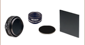
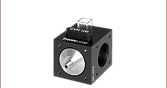
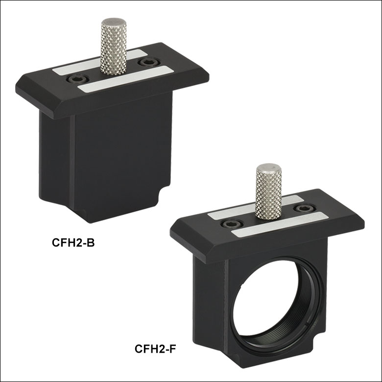
Zoom- Extra Removable Filter Holders for the In-Line Fiber Optic Filter Mounts
- CFH2-F Filter Holder Mounts Ø1" Filters up to 0.31" (8.0 mm) Thick
- CFH2-B Blank Filter Holder for Custom Designs
- Light Tight When Used with the Mounts Sold Above
These Removable Filter Holders integrate easily into the In-Line Fiber Optic Filter Mounts sold above. Extra filter holders allow users to replace lost components or quickly swap between filters during an experiment. Two top-located, laser-engraved boxes allow the user to label the filter holder with for easy identification of the mounted optic. Up to two filter holders can be slotted in an in-line filter mount.
The CFH2-F can accommodate Ø1" optics up to 0.31" (8.0 mm) thick and is equipped with SM1 threading (1.035"-40), making it compatible with any of Thorlabs’ SM1-threaded components. In addition, the CFH2-B Blank Plate can be used as a manual shutter or machined to suit your specific requirements.

 Zoom
Zoom
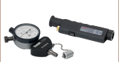
Click to Enlarge
Pushing the adjuster down on the CFH2-V quickly closes the shutter.
- Attenuates Light with a Vertical Shutter
- Black Oxide Coating Minimizes Back Reflections
- 3/16"-120 Adjuster Provides ±0.01 dB Attenuation Resolution (Ø200 - Ø1000 µm Core, 0.22 - 0.50 NA Fiber)
- Quickly Close Aperture by Pressing Down on Adjuster (See Photo the the Right)
- Light Tight When Used with the Mounts Sold Above
The CFH2-V is a variable attenuator insert compatible with the In-Line Fiber Optic Filter Mounts sold above. This insert is equipped with a black-oxide-coated variable shutter to partially or fully block light. The shutter moves vertically from the top across the Ø0.54" aperture and is controlled with an 3/16"-120 adjuster. When used with Ø200 - Ø1000 µm, 0.22 - 0.50 NA multimode fiber and a maximum 0.50" beam diameter, the CFH2-V can provide at least 0.01 dB attenuation resolution. Fine adjustments on the adjuster can be performed using the included 5/64" hex key. To quickly close the shutter, press the adjuster down (see photo above); letting go of the adjuster will return the shutter to the set position (within 0.0005").

 Zoom
Zoom
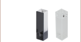
- Black Anodized Aluminum Cover for Our In-Line Fiber Filter Mounts
- Interior Geometry Allows for a Snug, Light-Tight Fit
- Accomodates Cuvettes up to 50 mm (1.96") Tall, Including the Stopper
The FOFM-CV is a light-tight cover that is compatible with the In-Line Fiber Optic Filter Mounts sold above. The cover protects the cuvettes that are being held from stray and ambient light that would enter from the top of the holder, as shown in the image to the right. Once placed on a filter mount, there will be 1.15" (29.2 mm) between the mount and the lid.
The cuvetter holder is designed to accomate cuvettes up to 50 mm (1.96") tall, including the stopper. Please note that the FOFM-CV is not compatible with the CFH2-V attenuator insert.