 Products Home
Beam Samplers
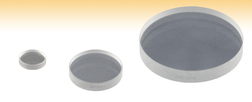
- Available in 1/2", 1", or 2" Diameter
- Fresnel Reflections at 45° for 1% to 10% Reflectance,
Depending on Polarization - AR-Coated Back Surface to Minimize Ghosting
- 0.5° Wedge to Eliminate Interference Fringes
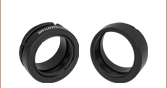
BSF05-A
Ø1/2"
BSF10-A
Ø1"
BSF20-A
Ø2"


Please Wait
| Specifications | |||
|---|---|---|---|
| Diameter | Ø1/2" (Ø12.7 mm) |
Ø1" (Ø25.4 mm) |
Ø2" (Ø50.8 mm) |
| Diameter Tolerance | +0.0/-0.2 mm | ||
| Thickness | 3 mm | 5 mm | 8 mm |
| Center Thickness Tolerance | ±0.1 mm | ±0.4 mm | |
| Material | UV Fused Silicaa | ||
| Surface Flatness | λ/10 @ 633 nm Over the Clear Aperture | ||
| Wedge | 30 ± 10 arcmin | ||
| Surface Quality | 20-10 (Scratch-Dig) | ||
| Front Surface Coating | None | ||
| Back Surface Coating | Broadband AR Coating R<1.0% Average within Wavelength Range |
||
| Clear Aperture | >90% of the Diameter | ||

| Damage Threshold Specifications | |
|---|---|
| Coating Designation (Item # Suffix) |
Damage Threshold |
| -UV | 5.0 J/cm2 (355 nm, 10 ns, 10 Hz, Ø0.350 mm) |
| -A | 7.5 J/cm2 (532 nm, 10 ns, 10 Hz, Ø0.491 mm) |
| -B | 0.246 J/cm2 (800 nm, 99 fs, 1 kHz, Ø0.166 mm) 7.5 J/cm2 (810 nm, 10 ns, 10 Hz, Ø0.133 mm) |
| -C | 7.5 J/cm2 (1542 nm, 10 ns, 10 Hz, Ø0.189 mm) |
Features
- UV Fused Silica Substrate
- Ø1/2", Ø1", and Ø2" Sizes
- Back Surface AR Coated to Minimize Ghosting
- 0.5° Wedged to Eliminate Interference Fringes
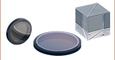
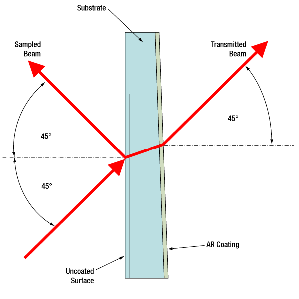
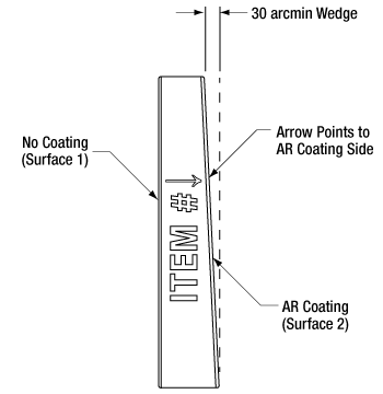
These beam samplers utilize the Fresnel reflection from an uncoated optical surface (indicated on the edge of the optic as shown on the Drawing tab) to pick off 1-10% of an incident beam, depending on the incident light's polarization. With a 45° angle of incidence and a p-polarized light field, the beamsplitter will provide approximately 1% reflection, while an s-polarized light field will provide approximately 10% reflection. See the Graphs tab for detailed plots of the reflectance as a function of polarization and angle of incidence.
These laser-quality beamsplitters are typically used for monitoring applications where optical losses and wavefront distortions of the transmitted beam need to be kept to a minimum. The back surface is wedged to eliminate internal fringes and AR coated to minimize ghosting. The beam samplers may also be used as beam combiners by reflecting a beam from the uncoated front surface and transmitting a beam through the back surface.
These beam samplers are fabricated from UV fused silica. They are recommended for applications that require minimal wavefront distortion over a larger operating temperature range. In addition, UV fused silica exhibits virtually no laser-induced fluorescence (as measured at 193 nm), making it an ideal choice for applications from the UV to the near IR.
In addition to these wedged beam samplers, Thorlabs also offers N-BK7 and UV fused silica wedged windows. These wedges are available both uncoated and AR coated.
Click for Details
The beam is sampled by reflecting a small percentage of the incident light from the uncoated surface.
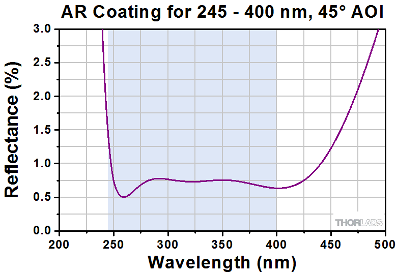
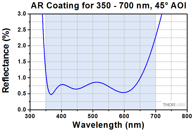
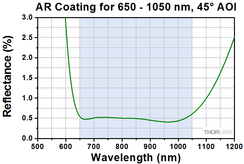
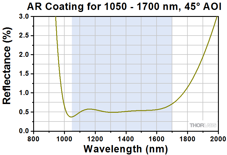
Each UV Fused Silica Beam Sampler is available with one of the following broadband AR coatings: 245 - 400 nm (designated with -UV), 350 - 700 nm (designated with -A), 650 - 1050 nm (designated as -B), or 1050-1700 nm (designated as -C). These high-performance multilayer AR coatings are designed for a 45° angle of incidence (0.5 NA). The plot shown below indicates the performance of the standard coatings in this family as a function of wavelength. Broadband coatings have a typical absorption of 0.25%, which is not shown in the reflectance plots.
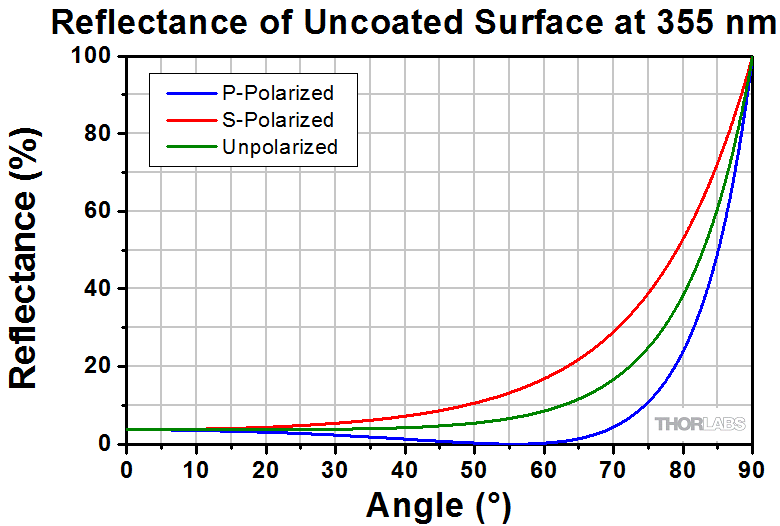
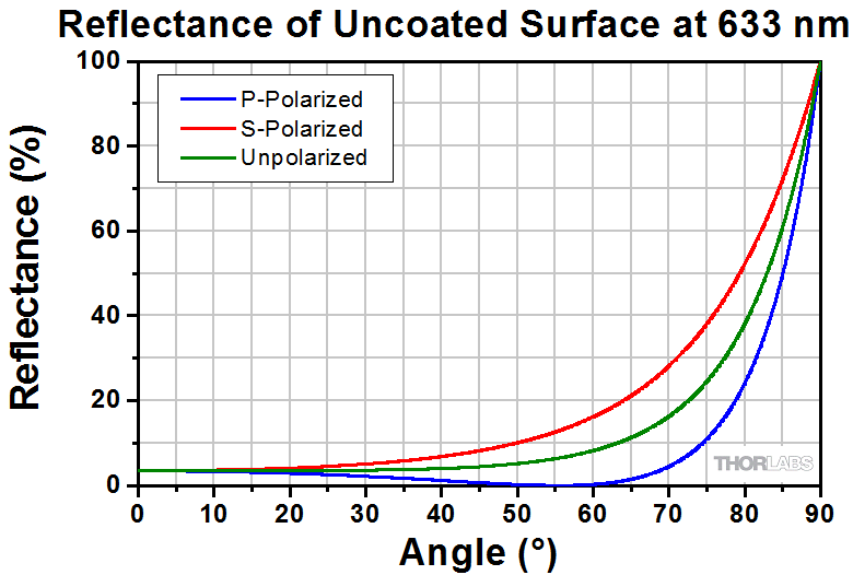
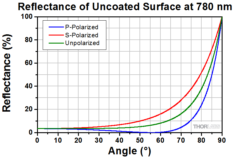
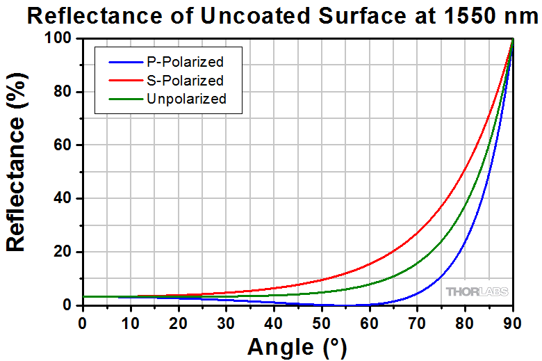
These beam samplers are intended to be used with the beam incident on the uncoated surface, as shown in the drawing to the right. The graphs below and to the left show the reflectance of the uncoated surface at popular wavelengths within each coating range over incident angles from 0 to 90°.
Beam Samplers with AR Coating for 245 - 400 nm
Click to Enlarge
Click Here for Data
The sampled beam is reflected from the uncoated surface of the beam sampler. The plot above shows the percent of the incident beam reflected by the uncoated surface of the optic over a range of incident angles. The mirrors are optimized for use at a 45° AOI.
Click to Enlarge
Click Here for Data
The back surface of each beam sampler with an item # ending in -UV is AR coated for
245 - 400 nm, minimizing back reflections of the transmitted beam at this surface.
Beam Samplers with AR Coating for 350 - 700 nm
Click to Enlarge
Click Here for Data
The sampled beam is reflected from the uncoated surface of the beam sampler. The plot above shows the percent of the incident beam reflected by the uncoated surface of the optic over a range of incident angles. The mirrors are optimized for use at a 45° AOI.
Click to Enlarge
Click Here for Data
The back surface of each beam sampler with an item # ending in -A is AR coated for 350 - 700 nm, minimizing back reflections of the transmitted beam at this surface.
Beam Samplers with AR Coating for 650 - 1050 nm
Click to Enlarge
Click Here for Data
The sampled beam is reflected from the uncoated surface of the beam sampler. The plot above shows the percent of the incident beam reflected by the uncoated surface of the optic over a range of incident angles. The mirrors are optimized for use at a 45° AOI.
Click to Enlarge
Click Here for Data
The back surface of each beam sampler with an item # ending in -B is AR coated for 650 - 1050 nm, minimizing back reflections of the transmitted beam at this surface.
Beam Samplers with AR Coating for 1050 - 1700 nm
Click to Enlarge
Click Here for Data
The sampled beam is reflected from the uncoated surface of the beam sampler. The plot above shows the percent of the incident beam reflected by the uncoated surface of the optic over a range of incident angles. The mirrors are optimized for use at a 45° AOI.
Click to Enlarge
Click Here for Data
The back surface of each beam sampler with an item # ending in -C is AR coated for 1050 - 1700 nm, minimizing back reflections of the transmitted beam at this surface
| Damage Threshold Specifications | |
|---|---|
| Coating Designation (Item # Suffix) |
Damage Threshold |
| -UV | 5.0 J/cm2 (355 nm, 10 ns, 10 Hz, Ø0.350 mm) |
| -A | 7.5 J/cm2 (532 nm, 10 ns, 10 Hz, Ø0.491 mm) |
| -B | 0.246 J/cm2 (800 nm, 99 fs, 1 kHz, Ø0.166 mm) 7.5 J/cm2 (810 nm, 10 ns, 10 Hz, Ø0.133 mm) |
| -C | 7.5 J/cm2 (1542 nm, 10 ns, 10 Hz, Ø0.189 mm) |
Damage Threshold Data for Thorlabs' UV Fused Silica Beam Samplers
The specifications to the right are measured data for Thorlabs' UV fused silica beam samplers. Damage threshold specifications are constant for a given coating type, regardless of the size of the beam sampler.
Laser Induced Damage Threshold Tutorial
The following is a general overview of how laser induced damage thresholds are measured and how the values may be utilized in determining the appropriateness of an optic for a given application. When choosing optics, it is important to understand the Laser Induced Damage Threshold (LIDT) of the optics being used. The LIDT for an optic greatly depends on the type of laser you are using. Continuous wave (CW) lasers typically cause damage from thermal effects (absorption either in the coating or in the substrate). Pulsed lasers, on the other hand, often strip electrons from the lattice structure of an optic before causing thermal damage. Note that the guideline presented here assumes room temperature operation and optics in new condition (i.e., within scratch-dig spec, surface free of contamination, etc.). Because dust or other particles on the surface of an optic can cause damage at lower thresholds, we recommend keeping surfaces clean and free of debris. For more information on cleaning optics, please see our Optics Cleaning tutorial.
Testing Method
Thorlabs' LIDT testing is done in compliance with ISO/DIS 11254 and ISO 21254 specifications.
First, a low-power/energy beam is directed to the optic under test. The optic is exposed in 10 locations to this laser beam for 30 seconds (CW) or for a number of pulses (pulse repetition frequency specified). After exposure, the optic is examined by a microscope (~100X magnification) for any visible damage. The number of locations that are damaged at a particular power/energy level is recorded. Next, the power/energy is either increased or decreased and the optic is exposed at 10 new locations. This process is repeated until damage is observed. The damage threshold is then assigned to be the highest power/energy that the optic can withstand without causing damage. A histogram such as that below represents the testing of one BB1-E02 mirror.
The photograph above is a protected aluminum-coated mirror after LIDT testing. In this particular test, it handled 0.43 J/cm2 (1064 nm, 10 ns pulse, 10 Hz, Ø1.000 mm) before damage.
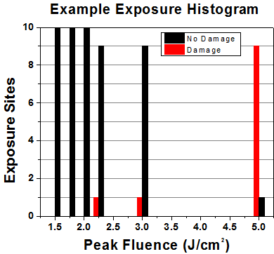
| Example Test Data | |||
|---|---|---|---|
| Fluence | # of Tested Locations | Locations with Damage | Locations Without Damage |
| 1.50 J/cm2 | 10 | 0 | 10 |
| 1.75 J/cm2 | 10 | 0 | 10 |
| 2.00 J/cm2 | 10 | 0 | 10 |
| 2.25 J/cm2 | 10 | 1 | 9 |
| 3.00 J/cm2 | 10 | 1 | 9 |
| 5.00 J/cm2 | 10 | 9 | 1 |
According to the test, the damage threshold of the mirror was 2.00 J/cm2 (532 nm, 10 ns pulse, 10 Hz, Ø0.803 mm). Please keep in mind that these tests are performed on clean optics, as dirt and contamination can significantly lower the damage threshold of a component. While the test results are only representative of one coating run, Thorlabs specifies damage threshold values that account for coating variances.
Continuous Wave and Long-Pulse Lasers
When an optic is damaged by a continuous wave (CW) laser, it is usually due to the melting of the surface as a result of absorbing the laser's energy or damage to the optical coating (antireflection) [1]. Pulsed lasers with pulse lengths longer than 1 µs can be treated as CW lasers for LIDT discussions.
When pulse lengths are between 1 ns and 1 µs, laser-induced damage can occur either because of absorption or a dielectric breakdown (therefore, a user must check both CW and pulsed LIDT). Absorption is either due to an intrinsic property of the optic or due to surface irregularities; thus LIDT values are only valid for optics meeting or exceeding the surface quality specifications given by a manufacturer. While many optics can handle high power CW lasers, cemented (e.g., achromatic doublets) or highly absorptive (e.g., ND filters) optics tend to have lower CW damage thresholds. These lower thresholds are due to absorption or scattering in the cement or metal coating.
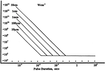
LIDT in linear power density vs. pulse length and spot size. For long pulses to CW, linear power density becomes a constant with spot size. This graph was obtained from [1].
Pulsed lasers with high pulse repetition frequencies (PRF) may behave similarly to CW beams. Unfortunately, this is highly dependent on factors such as absorption and thermal diffusivity, so there is no reliable method for determining when a high PRF laser will damage an optic due to thermal effects. For beams with a high PRF both the average and peak powers must be compared to the equivalent CW power. Additionally, for highly transparent materials, there is little to no drop in the LIDT with increasing PRF.
In order to use the specified CW damage threshold of an optic, it is necessary to know the following:
- Wavelength of your laser
- Beam diameter of your beam (1/e2)
- Approximate intensity profile of your beam (e.g., Gaussian)
- Linear power density of your beam (total power divided by 1/e2 beam diameter)
Thorlabs expresses LIDT for CW lasers as a linear power density measured in W/cm. In this regime, the LIDT given as a linear power density can be applied to any beam diameter; one does not need to compute an adjusted LIDT to adjust for changes in spot size, as demonstrated by the graph to the right. Average linear power density can be calculated using the equation below.

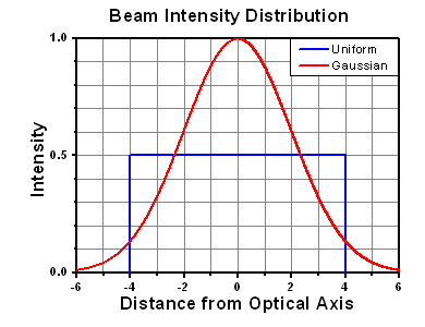
The calculation above assumes a uniform beam intensity profile. You must now consider hotspots in the beam or other non-uniform intensity profiles and roughly calculate a maximum power density. For reference, a Gaussian beam typically has a maximum power density that is twice that of the uniform beam (see lower right).
Now compare the maximum power density to that which is specified as the LIDT for the optic. If the optic was tested at a wavelength other than your operating wavelength, the damage threshold must be scaled appropriately. A good rule of thumb is that the damage threshold has a linear relationship with wavelength such that as you move to shorter wavelengths, the damage threshold decreases (i.e., a LIDT of 10 W/cm at 1310 nm scales to 5 W/cm at 655 nm):

While this rule of thumb provides a general trend, it is not a quantitative analysis of LIDT vs wavelength. In CW applications, for instance, damage scales more strongly with absorption in the coating and substrate, which does not necessarily scale well with wavelength. While the above procedure provides a good rule of thumb for LIDT values, please contact Tech Support if your wavelength is different from the specified LIDT wavelength. If your power density is less than the adjusted LIDT of the optic, then the optic should work for your application.
Please note that we have a buffer built in between the specified damage thresholds online and the tests which we have done, which accommodates variation between batches. Upon request, we can provide individual test information and a testing certificate. The damage analysis will be carried out on a similar optic (customer's optic will not be damaged). Testing may result in additional costs or lead times. Contact Tech Support for more information.
Pulsed Lasers
As previously stated, pulsed lasers typically induce a different type of damage to the optic than CW lasers. Pulsed lasers often do not heat the optic enough to damage it; instead, pulsed lasers produce strong electric fields capable of inducing dielectric breakdown in the material. Unfortunately, it can be very difficult to compare the LIDT specification of an optic to your laser. There are multiple regimes in which a pulsed laser can damage an optic and this is based on the laser's pulse length. The highlighted columns in the table below outline the relevant pulse lengths for our specified LIDT values.
Pulses shorter than 10-9 s cannot be compared to our specified LIDT values with much reliability. In this ultra-short-pulse regime various mechanics, such as multiphoton-avalanche ionization, take over as the predominate damage mechanism [2]. In contrast, pulses between 10-7 s and 10-4 s may cause damage to an optic either because of dielectric breakdown or thermal effects. This means that both CW and pulsed damage thresholds must be compared to the laser beam to determine whether the optic is suitable for your application.
| Pulse Duration | t < 10-9 s | 10-9 < t < 10-7 s | 10-7 < t < 10-4 s | t > 10-4 s |
|---|---|---|---|---|
| Damage Mechanism | Avalanche Ionization | Dielectric Breakdown | Dielectric Breakdown or Thermal | Thermal |
| Relevant Damage Specification | No Comparison (See Above) | Pulsed | Pulsed and CW | CW |
When comparing an LIDT specified for a pulsed laser to your laser, it is essential to know the following:
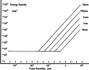
LIDT in energy density vs. pulse length and spot size. For short pulses, energy density becomes a constant with spot size. This graph was obtained from [1].
- Wavelength of your laser
- Energy density of your beam (total energy divided by 1/e2 area)
- Pulse length of your laser
- Pulse repetition frequency (prf) of your laser
- Beam diameter of your laser (1/e2 )
- Approximate intensity profile of your beam (e.g., Gaussian)
The energy density of your beam should be calculated in terms of J/cm2. The graph to the right shows why expressing the LIDT as an energy density provides the best metric for short pulse sources. In this regime, the LIDT given as an energy density can be applied to any beam diameter; one does not need to compute an adjusted LIDT to adjust for changes in spot size. This calculation assumes a uniform beam intensity profile. You must now adjust this energy density to account for hotspots or other nonuniform intensity profiles and roughly calculate a maximum energy density. For reference a Gaussian beam typically has a maximum energy density that is twice that of the 1/e2 beam.
Now compare the maximum energy density to that which is specified as the LIDT for the optic. If the optic was tested at a wavelength other than your operating wavelength, the damage threshold must be scaled appropriately [3]. A good rule of thumb is that the damage threshold has an inverse square root relationship with wavelength such that as you move to shorter wavelengths, the damage threshold decreases (i.e., a LIDT of 1 J/cm2 at 1064 nm scales to 0.7 J/cm2 at 532 nm):

You now have a wavelength-adjusted energy density, which you will use in the following step.
Beam diameter is also important to know when comparing damage thresholds. While the LIDT, when expressed in units of J/cm², scales independently of spot size; large beam sizes are more likely to illuminate a larger number of defects which can lead to greater variances in the LIDT [4]. For data presented here, a <1 mm beam size was used to measure the LIDT. For beams sizes greater than 5 mm, the LIDT (J/cm2) will not scale independently of beam diameter due to the larger size beam exposing more defects.
The pulse length must now be compensated for. The longer the pulse duration, the more energy the optic can handle. For pulse widths between 1 - 100 ns, an approximation is as follows:

Use this formula to calculate the Adjusted LIDT for an optic based on your pulse length. If your maximum energy density is less than this adjusted LIDT maximum energy density, then the optic should be suitable for your application. Keep in mind that this calculation is only used for pulses between 10-9 s and 10-7 s. For pulses between 10-7 s and 10-4 s, the CW LIDT must also be checked before deeming the optic appropriate for your application.
Please note that we have a buffer built in between the specified damage thresholds online and the tests which we have done, which accommodates variation between batches. Upon request, we can provide individual test information and a testing certificate. Contact Tech Support for more information.
[1] R. M. Wood, Optics and Laser Tech. 29, 517 (1998).
[2] Roger M. Wood, Laser-Induced Damage of Optical Materials (Institute of Physics Publishing, Philadelphia, PA, 2003).
[3] C. W. Carr et al., Phys. Rev. Lett. 91, 127402 (2003).
[4] N. Bloembergen, Appl. Opt. 12, 661 (1973).

In order to illustrate the process of determining whether a given laser system will damage an optic, a number of example calculations of laser induced damage threshold are given below. For assistance with performing similar calculations, we provide a spreadsheet calculator that can be downloaded by clicking the LIDT Calculator button. To use the calculator, enter the specified LIDT value of the optic under consideration and the relevant parameters of your laser system in the green boxes. The spreadsheet will then calculate a linear power density for CW and pulsed systems, as well as an energy density value for pulsed systems. These values are used to calculate adjusted, scaled LIDT values for the optics based on accepted scaling laws. This calculator assumes a Gaussian beam profile, so a correction factor must be introduced for other beam shapes (uniform, etc.). The LIDT scaling laws are determined from empirical relationships; their accuracy is not guaranteed. Remember that absorption by optics or coatings can significantly reduce LIDT in some spectral regions. These LIDT values are not valid for ultrashort pulses less than one nanosecond in duration.
Figure 71A A Gaussian beam profile has about twice the maximum intensity of a uniform beam profile.
CW Laser Example
Suppose that a CW laser system at 1319 nm produces a 0.5 W Gaussian beam that has a 1/e2 diameter of 10 mm. A naive calculation of the average linear power density of this beam would yield a value of 0.5 W/cm, given by the total power divided by the beam diameter:
However, the maximum power density of a Gaussian beam is about twice the maximum power density of a uniform beam, as shown in Figure 71A. Therefore, a more accurate determination of the maximum linear power density of the system is 1 W/cm.
An AC127-030-C achromatic doublet lens has a specified CW LIDT of 350 W/cm, as tested at 1550 nm. CW damage threshold values typically scale directly with the wavelength of the laser source, so this yields an adjusted LIDT value:
The adjusted LIDT value of 350 W/cm x (1319 nm / 1550 nm) = 298 W/cm is significantly higher than the calculated maximum linear power density of the laser system, so it would be safe to use this doublet lens for this application.
Pulsed Nanosecond Laser Example: Scaling for Different Pulse Durations
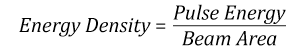
Suppose that a pulsed Nd:YAG laser system is frequency tripled to produce a 10 Hz output, consisting of 2 ns output pulses at 355 nm, each with 1 J of energy, in a Gaussian beam with a 1.9 cm beam diameter (1/e2). The average energy density of each pulse is found by dividing the pulse energy by the beam area:
As described above, the maximum energy density of a Gaussian beam is about twice the average energy density. So, the maximum energy density of this beam is ~0.7 J/cm2.
The energy density of the beam can be compared to the LIDT values of 1 J/cm2 and 3.5 J/cm2 for a BB1-E01 broadband dielectric mirror and an NB1-K08 Nd:YAG laser line mirror, respectively. Both of these LIDT values, while measured at 355 nm, were determined with a 10 ns pulsed laser at 10 Hz. Therefore, an adjustment must be applied for the shorter pulse duration of the system under consideration. As described on the previous tab, LIDT values in the nanosecond pulse regime scale with the square root of the laser pulse duration:
This adjustment factor results in LIDT values of 0.45 J/cm2 for the BB1-E01 broadband mirror and 1.6 J/cm2 for the Nd:YAG laser line mirror, which are to be compared with the 0.7 J/cm2 maximum energy density of the beam. While the broadband mirror would likely be damaged by the laser, the more specialized laser line mirror is appropriate for use with this system.
Pulsed Nanosecond Laser Example: Scaling for Different Wavelengths
Suppose that a pulsed laser system emits 10 ns pulses at 2.5 Hz, each with 100 mJ of energy at 1064 nm in a 16 mm diameter beam (1/e2) that must be attenuated with a neutral density filter. For a Gaussian output, these specifications result in a maximum energy density of 0.1 J/cm2. The damage threshold of an NDUV10A Ø25 mm, OD 1.0, reflective neutral density filter is 0.05 J/cm2 for 10 ns pulses at 355 nm, while the damage threshold of the similar NE10A absorptive filter is 10 J/cm2 for 10 ns pulses at 532 nm. As described on the previous tab, the LIDT value of an optic scales with the square root of the wavelength in the nanosecond pulse regime:
This scaling gives adjusted LIDT values of 0.08 J/cm2 for the reflective filter and 14 J/cm2 for the absorptive filter. In this case, the absorptive filter is the best choice in order to avoid optical damage.
Pulsed Microsecond Laser Example
Consider a laser system that produces 1 µs pulses, each containing 150 µJ of energy at a repetition rate of 50 kHz, resulting in a relatively high duty cycle of 5%. This system falls somewhere between the regimes of CW and pulsed laser induced damage, and could potentially damage an optic by mechanisms associated with either regime. As a result, both CW and pulsed LIDT values must be compared to the properties of the laser system to ensure safe operation.
If this relatively long-pulse laser emits a Gaussian 12.7 mm diameter beam (1/e2) at 980 nm, then the resulting output has a linear power density of 5.9 W/cm and an energy density of 1.2 x 10⁻⁴ J/cm2 per pulse. This can be compared to the LIDT values for a WPQ10E-980 polymer zero-order quarter-wave plate, which are 5 W/cm for CW radiation at 810 nm and 5 J/cm2 for a 10 ns pulse at 810 nm. As before, the CW LIDT of the optic scales linearly with the laser wavelength, resulting in an adjusted CW value of 6 W/cm at 980 nm. On the other hand, the pulsed LIDT scales with the square root of the laser wavelength and the square root of the pulse duration, resulting in an adjusted value of 55 J/cm2 for a 1 µs pulse at 980 nm. The pulsed LIDT of the optic is significantly greater than the energy density of the laser pulse, so individual pulses will not damage the wave plate. However, the large average linear power density of the laser system may cause thermal damage to the optic, much like a high-power CW beam.
| Posted Comments: | |
cdolbashian
(posted 2024-06-24 04:19:04.0) Thank you for reaching out to us with this custom request. We can potentially change these components as you describe above. I have put you in contact with our customs team in order to fulfil this request. For future custom requests, feel free to email Techsales@thorlabs.com. Callum Watt
(posted 2024-06-12 15:37:07.667) Hi, I have read in a previous comment bellow that a marker indicating the position of the thicker end of the wedge was suggested to your internal engineering forum (comment on 2018-04-12). Has there been any update on this request? Is the orientation of the wedge with respect to the uncoated surface marker always the same? jpolaris
(posted 2024-06-21 01:35:01.0) Thank you for contacting Thorlabs. The engineering effort required to mark the wedge's thickest point on every beam sampler manufactured is not feasible for us at this time. However, I have reached out to you directly to discuss the possibility of fulfilling this request as a special order. Malo Raoul
(posted 2024-05-16 14:08:28.62) Hello, we are using the BSF10-C as a beam combiner, combining the light on the S1 face and we would like to know if you offer a product without the wedge, and only coated on one side. Thank you cdolbashian
(posted 2024-05-28 10:59:45.0) Thank you for reaching out to us with this inquiry. What you want seems to be a non-wedged, UVFS window which is only AR coated on one side. We can definitely do this as a custom. I have reached out to you directly in order to facilitate a custom such as this. prathmesh ghag
(posted 2023-10-18 12:43:45.79) I have a circularly polarized collimated beam. I want to sample the light out by intensity division. But I dont want to change the original circularity. Can you suggest a solution for this application?
Also do you have non polarizing samplers giving approx 1-5% of the intensity? Fabio Novelli
(posted 2023-02-28 16:42:23.523) Hello,
What is the typical Transmission % for a p-polarized beam at 45 degrees?
Is R+T>99% for BSF10-B?
Best,
Fabio jgreschler
(posted 2023-03-02 02:26:34.0) Thank you for reaching out to Thorlabs. You can see a graph and download the raw data of the reflectance in the "graphs" tab of this product page. At 45 degrees, the P polarized reflectance percentage is 0.7433. user
(posted 2022-04-23 17:00:27.21) Hi team, a perhaps very naïve question: what is the difference between your beam sampler and non-polarising beam splitter products? Is it just that the latter has a wider range of specified split ratio, while the former relies on just the Fresnel reflection? Are there certain use cases I should pick one over the other? Thanks in advance. jdelia
(posted 2022-05-12 01:25:50.0) Thank you for contacting Thorlabs. A beam sampler utilizes Fresnel reflections of an uncoated optical surface to pick off about 1-10% of the light, which is also dependent on the polarization of the light. Beam splitters have a dielectric coating optimized for a chosen wavelength range deposited on the front surface. The beam samplers also have a 0.5 degree wedge to eliminate interference fringes. Additionally, like you mentioned, the beamsplitters have a larger range of R:T ratios, while the beam sampler is generally intended for 1-10%, though this can change with angle. I have contacted you directly to discuss your application. Lin Su
(posted 2021-06-28 01:11:25.323) Is the reflectivity curve different for S and P polarization for the AR coated surface? Do you have data on it? Thanks in advance! YLohia
(posted 2021-06-28 02:33:36.0) Hello Lin, the data presented here is the average of the S and P polarization reflectivities. I have reached out to you directly with curves for S and P reflectivities (theoretical). Garnet Cameron
(posted 2020-09-14 17:03:43.247) The reflectance graph provided is for 45 degree AOI. Is this AR coating the same for WW41050-C? I am interested in the R at 8 degree AOI. YLohia
(posted 2020-09-15 01:16:16.0) We have at least two versions of the UV/VIS/NIR/telecom AR coatings (-UV, -A, -B, -C) -- one designed for 0 degrees AOI (on windows, lenses, etc), and one designed at 45 degrees (on the beam samplers). I have reached out to you directly with data. Steffen Hädrich
(posted 2020-07-27 11:16:22.94) What is the AR coating characteristic at close to AOI=0° (likely 5-10°). Can you please send curves or data on this? nbayconich
(posted 2020-07-27 03:33:05.0) Thank you for contacting Thorlabs. Please see the link below to our AR coating curves below, we have reflection plots for the –UV, -A, -B & -C coatings measured at 8° AOI.
https://www.thorlabs.com/newgrouppage9.cfm?objectgroup_id=5840&tabname=AR%20coating user
(posted 2019-07-24 23:30:41.78) Dear supportor
I’m Jongkeun Yang in south korea.
I have a interesting about BSF10-A.
So, would you please inform me that reflectance (%) of 400 to 700 nm wavelength?
Thanks tcampbell
(posted 2019-07-25 09:51:54.0) Hello, thank you for contacting Thorlabs. Reflectance data for these beam samplers can be found on the Graphs tab. Sai Kanth Dacha
(posted 2019-03-19 17:36:34.507) I purchased a BSF10-C recently. I have a 1064 nm laser that is putting out linearly polarized, ~138 uJ, 1.3 ns pulses at 1 kHz. The input beam, about 3.1 mm wide, is incident on the uncoated surface. I am observing significant ghosting in reflection: I can see, on the IR card, two distinct spots with similar brightness. Isn't the AR coating supposed to prevent this? I'm pretty sure that I'm well below the damage threshold as well. Please let me know if this has been reported before. nbayconich
(posted 2019-04-01 11:00:39.0) Thank you for contacting Thorlabs. The reflection off the AR coated surface should be less than 1.0%. Depending on the sensitivity of your viewing card if the incident source has enough power the ghost reflection could still be detectable.
What angle of incidence is your source on the un-coated surface of the beam sampler? Is your source S or P polarized with respect to the beam sampler's un-coated surface?
It would be best to know the exact power measurements of your reflected beams. A techsuppport representative will reach out to you directly to discuss your application. caleb.anderson
(posted 2018-07-05 14:39:38.37) Hello,
I've got a high power laser diode stack (Max power ~600 W) of which I am trying to characterize the wavelength. However, the spectrometers I have come across have either extremely low LIDTs or would be saturated by the laser beam. I don't currently have a way to characterize the width of the beam as it is complex, and it is in the IR spectrum, so it cannot be visibly characterized. Would I be able to use this to sample a portion of the beam in a spectrometer, at least at lower power levels? YLohia
(posted 2018-07-06 08:43:40.0) You can use the beam sampler you were looking at to reduce the amount of power going into your spectrometer and avoid saturation. Alternately, you could use one of the neutral density filters from this page as well for a more specific attenuation: https://www.thorlabs.com/navigation.cfm?guide_id=2185 user
(posted 2018-04-11 07:46:40.983) Any change to add the marking for the wedge's widest point? YLohia
(posted 2018-04-12 09:35:55.0) Hello, thank you for contacting Thorlabs. Marking the wedge's widest point was one of the ideas suggested to be able to tell the back and front surfaces apart from each other. As a solution to this problem, we have implemented an engraved arrow that points towards the uncoated surface. That being said, I have posted your request for a marking for the widest point in our internal engineering forum. user
(posted 2015-10-01 21:20:38.99) Good product, but these windows have serious birefringence. We were using these before a half wave plate/ polarizing beamsplitter and were troubleshooting why the extinction ratio was so poor; it was because our sampler was making the beam semi-circularly polarized. You should mention this somewhere in the datasheet. besembeson
(posted 2015-10-09 11:42:58.0) Response from Bweh at Thorlabs USA: Thanks for the feedback. According to our tests though, we have not seen any birefringence from these. Birefringence can be introduced if the optic is clamped too hard. Maybe you try less-tightening when holding the optic. arlen.biersgreen.1
(posted 2015-08-07 13:35:42.59) How do I calculate the offset in the transmitted beam from my incident beam? That is, what are the relevant coefficients of refraction for the layers on the sampler so that I can do the calculation? Thanks. jlow
(posted 2015-08-25 03:39:55.0) Response from Jeremy at Thorlabs: You can see the UVFS refractive index graph at http://www.thorlabs.com/newgrouppage9.cfm?objectgroup_id=6973&tabname=UV%20Fused%20Silica. The AR coating is very thin relative to the substrate so the offset from that should be negligible. However, the back surface does have a 0.5° angle relative to the front surface so that would needs to be taken into account. chris.middleton
(posted 2015-04-24 13:04:12.707) I believe the beam samplers would work better with your standard mirror mounts (e.g., KM100) if the AR coating was on the non-wedged surface. Assuming that (1) you want to be incident (45 deg) on the the uncoated surface and (2) that you want the cylindrical surface of the BSF to be concentric with the mount's well that accepts the optic, you can get twice as much beam clearance if the AR coating was on the non-wedged surface. Contact me if you would like drawings. cdaly
(posted 2015-04-29 08:28:10.0) Response from Chris at Thorlabs: Thank you for your feedback. The uncoated surface is the one from which the beam would be sampled. In the KM100 mount this would put this face towards the front face of the mount, seated against the internal lip. These beam samplers can also be used with the clear edge mount for 1" optics (KM1CE) or clear quadrant mounts for 1/2" optics. (KM05FL/KM05FR) if any further beam clearance is required. jhinr
(posted 2014-02-28 12:07:15.517) Hello,
I am interested in the spectral response (transmission and refelction) for a broad wavelength range. We are looking for a beam sampler for monitoring in a spectroscopic application, where we look at signals from 400nm to about 2.2um, and we could only use one beam sampler (there is not much space available). Hence it would be nice to know how the transmission and reflection are affected by the coatings in this range. Do you have any data about this?
Regards,
Johannes Hinrichs besembeson
(posted 2014-03-05 02:31:41.0) Response from Bweh E. at Thorlabs: We have the theoretical reflectivity graphs for these AR coatings outside the design wavelength range. I will share these with you via email. xxu
(posted 2014-02-20 21:51:04.297) The propagation direction of the transmitted beam is changed after the beam sampler. Because there is no marking of which direction the wedge between the front and back surface of the sampler is, I cannot rotate the beam sampler to at least make the beam stay in the vertical or horizontal plane.
I think this beam sampler is of little help for systems that needs high precision alignment. cdaly
(posted 2014-02-25 05:14:04.0) Response from Chris at Thorlabs: Thank you for your feedback. I agree some sort of marking, at the wedge's widest point for example, would make it easier to keep the beam in given plane. We will discuss this internally. Perhaps we can have one added in the future. iraj.kavosh
(posted 2013-12-10 11:11:30.427) Hi, Please include:
(1) Laser damage threshold for CW & Pulsed modes
(2) Reflectivity vs wavelength in case the laser wavelength is outside of the Sampler range. Or, we need to split off more power by selecting a different Sampler.
Thanks. jlow
(posted 2014-01-08 04:53:50.0) Response from Jeremy at Thorlabs: The pulsed damage threshold located in the overview tab on the webpage, under the specifications table. For the BSF10-C, it is 7.5 J/cm^2 (1542 nm, 10 ns, 10 Hz, Ø0.189 mm). For CW, we do not have a laser with high enough power to destroy the coating. The BSF10-C was able to withstand around 3 kW/cm without being damaged. We can provide out of band reflectivity. I will get in contact with you directly to provide this. johanna.tragardh
(posted 2013-08-12 16:24:54.82) Hi, I would like to use the beam sampler to pick off light from a broad band (tuneable) laser. What is the reflectivity of the AR coating substantially outside the range (say 350-2000 nm for the visible coating?) Your graph ends at 2%. Alternatively is it possible to get these beam samplers without AR coating? jlow
(posted 2013-08-12 10:37:00.0) Response from Jeremy at Thorlabs: The reflectivity of the AR coating is going to be quite high outside of the specified region. For the uncoated version, we have the stock WW41050 (http://www.thorlabs.com/newgrouppage9.cfm?objectgroup_id=5546&pn=WW41050) available which have better surface quality and flatness. wwbsghr
(posted 2013-01-28 09:45:47.287) Dear Sir/Madam, I would like to know the damage threshold for BSF10-UV.Can it be used as sampler for 10Hz laser(283nm,50mj/pulse,D3mm;355nm,180mj/pulse,D5mm)? bdada
(posted 2012-03-15 11:21:00.0) Response from Buki at Thorlabs to zhgaom:
Thank you for participating in our feedback forum. The damage threshold for our UVFS beam samplers is 5J/cm^2 for an 810nm laser, 10ns, 10Hz, with spot size of 0.158mm. Based on the data you provided, our beam samplers should be suitable. Please test one and contact TechSupport@thorlabs.com if you experience any issues. zhgaom
(posted 2012-03-14 02:08:11.0) Dear Sir/Madam,
I would like to know the damage threshold for BSF5-UV and BSF5-A. We currently have two lasers. One is Nd:YAG working at 220mJ@532nm and 20mJ @266nm. The typical repetition rate is 5Hz. As the beam diameter is 5mm, it gives the power/energy density as and 5.5W/cm^2, 1.1J/cm^2, respectively. The other laser we have is a Nd:YLF laser working at 527nm, typical pulse energy is 25mJ@1000Hz. Would you have proper beam sampler so that I can sample those laser and monitor them using a energy meter? Greg
(posted 2010-11-16 10:22:46.0) A response from Greg at Thorlabs: We recently performed damage threshold testing for a number of our optics. Among the tested optics was a B coated UVFS beam sampler. At this time, this is the only beam sampler that has undergone damage threshold testing. As we continue damage threshold testing, we will add more values to our website. The 100 mJ/cm2 mentioned in a previous feedback was a very conservative estimate before we performed damage threshold testing. If you would like more information regarding a product, please contact techsupport@thorlabs.com and we will be able to assist you further. user
(posted 2010-11-16 10:00:45.0) Is the damage threshold of the B coating (650-1050 nm) really higher than the others?
Actually, 100mJ/cm2 is mentioned in this post, whereas "5 J/cm2 (810 nm, 10 ns, 10 Hz)" is written for the B serie. Adam
(posted 2010-05-04 13:02:59.0) A response from Adam at Thorlabs to Sunqingzhen: All of the beam samplers should contain an arrow that points towards the uncoated surface. Since the arrow is drawn on, it is possible that the arrow was rubbed away. In the future we will use our engraver to ensure this does not happen. If you would like to test which surface is the coated surface, we suggest one of the following approaches:
Use a magnifier and look from the edge of the substrate in and you can see where the coating begins. Or you can hold in your hand on a angle and reflect the ambient light and see the coated side.
If you have trouble locating this surface we can exchange the unit for you. Adam
(posted 2010-05-04 12:59:20.0) A response from Adam at Thorlabs to sunqingzhen: The beam samplers do have an AR coating on the back surface that is meant to minimize the ghosting effect. Please note that this will not eliminate the ghosting effect especially for high power sources. I would like to contact you directly to get more information about your application. sunqingzhen
(posted 2010-05-03 23:20:07.0) I still have seen the ghosting, when the polarized laser is incident on the beam sampler at an angle of 45 degrees. sunqingzhen
(posted 2010-05-03 23:05:26.0) There is only a letter F on the sige of the beam sampler. Which is the AR coated surface?
I hadnt seen any arrow on the beam sampler! apalmentieri
(posted 2009-10-20 16:12:59.0) A response from Adam at Thorlabs: There should also be an arrow on the side of this optic. This arrow will point to the Ar coated surface. pmd
(posted 2009-10-20 15:54:32.0) The only mark on the edge of the optic is a letter F. With this mark how can I tell which is the AR coated surface? apalmentieri
(posted 2009-09-16 17:58:46.0) A response from Adam at Thorlabs: Currently we do not have beam splitters that can handle more power than 100mJ/cm^2. I will email you to try and get more information on the exact power of your Nd:Yag so I can find out if we can suggest any items that may work. daniel.fink
(posted 2009-09-16 17:45:52.0) Is there an alternative beam splitter which can handle more power than 100mJ/cm^2 as described below? What would you suggest for an 532nm ND:YAG laser? The splitted beam shall be used for power measurements and should have sth. like 5 to 10 % of the power. Thank you apalmentieri
(posted 2009-07-14 18:22:00.0) A response from Adam at Thorlabs: We are able to supply custom wavelength beamsplitters, but would require more information before we provide a quotation. I will contact you directly to get this information. hujianming
(posted 2009-07-14 16:58:14.0) Can you supply a beamsplitter with 400-900nm wavelength? If ok,how about the price?
Thank you very much. apalmentieri
(posted 2009-06-19 13:39:25.0) A response from Adam at Thorlabs: The damage threshold for these beamsamplers depend on the AR coatings. Currently, we can only provide an approximate damage threshold, which is 100W/cm^2 for CW laser and 100mJ/cm^2 for 10ns pulsed light. Please let me know if you have further questions. walter.schmoll
(posted 2009-06-19 09:45:56.0) How much power or pulse energy can these beam samplers handle? Greg
(posted 2009-03-23 15:19:33.0) A response from Greg at Thorlabs to dyanali: Thank you for your interest in our Beam Samplers. We have reflectivity data for these at 635 nm under the Graphs tab. We do not have data at 251 nm, but the reflection should be relatively consistent with the data at 635 nm. dyanali
(posted 2009-03-23 09:54:32.0) Hello,
What are the losses and reflectivity I can expect if I use one of the UVFS beam samplers to monitor a beam at 251nm?
Regards
Dyan Laurie
(posted 2008-03-31 16:05:32.0) Response from Laurie at Thorlabs to flickingerd: Thank you for noticing the typo under our specifications tab for the wedge angle. We have corrected that typo. As for the UV fused silica beam samplers, I have personally emailed you the theoretical reflectivity curve as a function of wavelength. Youll note that for 355 nm incident light, the average reflectivity for S and P polarized light incident at a 45 degree angle will be approximately 6%. Broadband coatings become more difficult to fabricate for shorter wavelengths; however, I have passed your suggestion for UV-coated beam samplers on to our optics engineers so that they can consider producing them in the future. Thank you for your interest in our products! flickingerd
(posted 2008-03-31 13:20:50.0) While Im at it, the wedge angle spec for the beam samplers (under the Specs tab) is written incorrectly, I think. Its written 30[deg] +/- 10 Arc Min, where [deg] is the little circle. The little circle should probably be replaced by a single quote, or the words "Arc Min" to avoid confusion. flickingerd
(posted 2008-03-31 13:11:53.0) About the UV fused silica beam samplers (BSF): why would you not offer your UV AR coating on your UV fused silica beam samplers? I would like one with the UV AR coating for use with a UV laser, but its probably not worth the wait to have one specially made right now. If you could email me the reflection off of the "A" coating for 355nm for now, that would be nice. technicalmarketing
(posted 2008-01-23 09:36:42.0) Dear Europe,
The laser windows are more expensive than the beam samplers because they have better scratch/dig specifications, they are coated on both sides, and the specialty coatings combined with the smaller production runs increase the cost per coating. europe
(posted 2008-01-22 10:16:40.0) Why are the Laser Windows (e.g. WG11050) more expensive than the beam samplers? Surface specs and product is nearly the same - and the sampler got even a wedge...? |
- Damage Threshold: 5.0 J/cm2 (355 nm, 10 ns, 10 Hz, Ø0.350 mm)
- Damage Threshold: 7.5 J/cm2 (532 nm, 10 ns, 10 Hz, Ø0.491 mm)
- Damage Threshold: 7.5 J/cm2 (810 nm, 10 ns, 10 Hz, Ø0.133 mm)