 Products Home
Wavelength Meter
- Measure Wavelength, Coherence Length, and Power of a Laser From 600 nm to 1700 nm
- Wavelength Accuracy: 1 ppm (Internal Reference) or 0.3 ppm (External Reference, ±25 MHz Accuracy)
- Control via Device Interface, Thorlabs' Software, or SCPI Commands
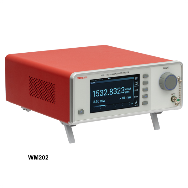
WM202
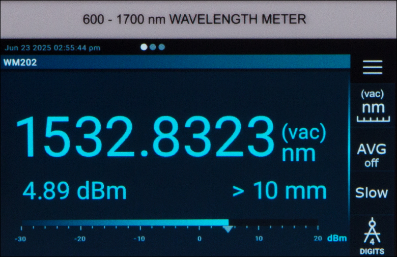
600 - 1700 nm Wavelength Meter
Application Idea
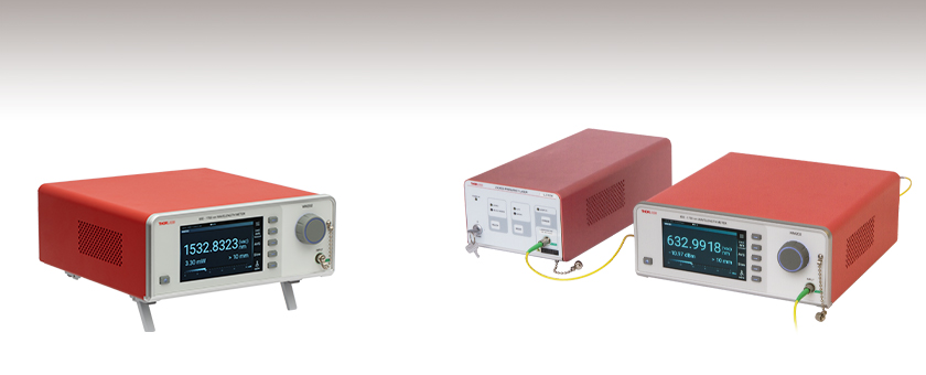
An external reference, such as the LLD1530 Frequency-Locked Laser, can be used with the WM202 Wavelength Meter for increased measurement accuracy.


Please Wait
| Table 1.1 Key Specifications | |
|---|---|
| Item # | WM202 |
| Wavelength Rangea | 600 to 1700 nm |
| Maximum Input Bandwidth | 10 GHz |
| Minimum Required Input Powerb | 2 to 40 µW |
| Wavelength Measurement Absolute Accuracy, Internal Reference | 1 ppm (1.5 pm at 1500 nm, 200 MHz at 200 THz)c,d |
| Wavelength Measurement Absolute Accuracy, External Reference | 0.3 ppm (0.45 pm at 1500 nm, 60 MHz at 200 THz)c,d,e |
| External Reference Laser Input | Wavelength Range: 1520 - 1580 nm Input Power Range: 0.2 - 5 mW Required Accuracy: ±25 MHz (±0.2 pm at 1550 nm) Maximum Bandwidth: 1 GHz |
| Power Measurement Accuracyf | ±1 dB |
| Coherence Length Measurement Rangeg | <10 mm/<1 mm |
| Measurement Speedg | 1 Hz/10 Hz |
| Optical Return Loss | >50 dB |
| Fiber Connector Type | Input: FC/APC, Wide Key (2.2 mm) External Reference Input: FC/APC, Narrow Key (2.0 mm) |
Features
- Scanning Michelson Interferometer with Internal Stable Reference Laser
- Measures the Wavelength, Coherence Length, and Power of a CW Laser from 600 to 1700 nm
- Use with Internal Reference Laser or an External Reference Laser (Thorlabs' LLD1530 Frequency-Locked Laser Recommended)
- Slow Scanning Mode at 1 Hz or Fast Scanning Mode at 10 Hz to Trade Off Accuracy for Measurement Speed
- Device Control Options:
- Directly With the Touchscreen Interface
- Remotely With a PC and Thorlabs’ OPM Software (USB or Ethernet Connection)
- Monitor Data Through a Web Viewer (Ethernet)
- Remote Control With SCPI Commands (USB, Ethernet, or RS232 Connection)
- Configurable Analog Output Error Signal for Feedback Loops
The WM202 Wavelength Meter is a compact, general-purpose wavelength meter designed for measuring the center wavelength of a CW laser from 600 to 1700 nm (bandwidth ≤10 GHz) with an absolute accuracy down to 0.3 parts per million. The power and coherence length of the laser are also measured simultaneously, allowing for the single longitudinal mode behavior of the input laser to be monitored. The input light is coupled into the device using an FC/APC fiber.
The wavelength meter consists of a scanning Michelson interferometer with an internal reference laser, enabling high-accuracy measurements and a quick start-up. Please see the Theory tab for details on the theory of operation of the device. The internal temperature-stabilized, distributed feedback (DFB) reference laser provides an absolute measurement accuracy of 1 ppm (1.5 pm at 1500 nm, 200 MHz at 200 THz). For improved accuracy, the wavelength meter can be used with an external reference laser (required accuracy ±25 MHz) in the 1520 to 1580 nm range, such as Thorlabs' LLD1530 Frequency-Locked Laser, with an accuracy of 0.3 ppm (0.45 pm at 1500 nm, 60 MHz at 200 THz). Table 1.1 lists the key specifications; see the Specs tab for the complete specifications.
Click to Enlarge
Click for Raw Data
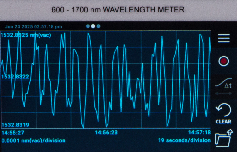
Figure 1.2 Wavelength stability measurement with the WM202 wavelength meter on an LLD1530 frequency-locked laser from a cold start, using the internal reference. The blue region in the graph is the 15-minute warm-up period, during which the accuracy specification is reduced.
The minimum input power for a measurement depends on the input wavelength, as seen in the graph in Figure 3.1 on the Graphs tab; it can measure down to 500 nm if the power is high enough. To achieve the accuracies mentioned above, the device must be calibrated once per year using an external stable laser with a known wavelength (accuracy ±25 MHz) in the instrument’s wavelength range, and recalibration is required when switching from the internal to the external reference. For an hour after calibration the wavelength measurement accuracy is 0.3 ppm with the internal reference; see the Specs tab for details. We offer a calibration service if an appropriate laser is not available. Note that if you are using the LLD1530 laser as an external reference, you can also use it for calibration by using a fiber-optic splitter to send the light to both inputs.
The stated accuracy specifications are for slow mode at 1 Hz; fast mode at 10 Hz offers increased speed, but reduced accuracy. A 15-minute warm-up period is required after the instrument is started up to reach optimal accuracy; see Figure 1.2 for a cold-start graph of the measured wavelength versus time with the accuracy tolerance shown. Example wavelength measurement results versus time for our TLX1 Tunable Laser and a HeNe laser are also shown in Figures 3.3 and 3.4 on the Graphs tab, respectively.
Device Interface and Remote Control
The high-resolution, backlit, color touchscreen provides a clear interface with several ways to monitor and control the wavelength measurement, such as the number of digits, averaging, statistics, and graphing. There is also an analog output that can be configured to give a signal proportional to the deviation from a chosen wavelength, for stabilizing the wavelength of an input laser in a feedback loop. The annual calibration with an external known wavelength reference can also be performed with the device's interface. Please see the images in the LCD Screen tab for images of the most commonly used screen views.
The WM202 wavelength meter can also be remotely controlled via three different interfaces: the high-speed USB interface, the built-in Ethernet, or the serial RS232 interface. Thorlabs provides a remote operation software interface for the wavelength meter as part of our Optical Power Monitor (OPM) Software, which can be run through a USB or network connection. The WM202 wavelength meter also has a built-in web server for monitoring the measurement results within a local area network; please see Figure 8.4 in the Software tab for a screenshot of the web viewer.
The WM202 wavelength meter's remote operation can also be integrated into custom-made measurement software with the help of the provided SCPI commands and drivers through any of the interfaces. Please see the Software tab for details on the OPM software, web viewer, and SCPI commands.

All wavelength accuracy specifications are the maximum wavelength/frequency error given according to the 3σ criterion for the slow measurement modea.
The laser being measured must be input with an FC/APC single mode fiber and have a maximum bandwidth of 10 GHz to achieve the specified wavelength accuracy. However, a measurement of the center wavelength of broadband sources, like superluminescent diodes, can be performed using FC/APC multimode fibers with a reduced absolute accuracy.
The unit nm (Air) is based on the definition by Peck & Reeder (T = 15.0 °C, P = 1013.25 hPa, 330 ppm CO2, and 0% relative humidity). This is the same definition that NIST uses in their Atomic Spectra Database (ASD)b.
- The 3σ criterion indicates that the wavelength measurement is expected to be within the specified error of the wavelength with 99.7% confidence.
- More details can be found in Edson R. Peck and Kaye Reeder, "Dispersion of Air," J. Opt. Soc. Am. 62, 958-962 (1972).
| Table 2.1 Measurement Specifications | |
|---|---|
| Item # | WM202 |
| Wavelength Rangea | 600 to 1700 nm |
| Maximum Input Bandwidth | 10 GHz |
| Minimum Required Input Powerb | 2 to 40 µW |
| Maximum Input Power | 10 mW |
| Wavelength Measurement Absolute Accuracy, Internal Reference | 5 ppm (7.5 pm at 1500 nm, 1 GHz at 200 THz)c 1 ppm (1.5 pm at 1500 nm, 200 MHz at 200 THz)c,d 0.3 ppm (0.45 pm at 1500 nm, 60 MHz at 200 THz)c,d,e |
| Wavelength Measurement Absolute Accuracy, External Reference | 0.3 ppm (0.45 pm at 1500 nm, 60 MHz at 200 THz)c,d,f |
| External Reference Laser Input | Wavelength Range: 1520 - 1580 nm Input Power Range: 0.2 - 5 mW Required Accuracy: ±25 MHz (±0.2 pm at 1550 nm) Maximum Bandwidth: 1 GHz |
| External Calibration Laser Input | Wavelength Range: 600 - 1700 nm Input Power Range: 0.2 - 5 mW Required Accuracy: ±25 MHz (±0.2 pm at 1550 nm) Maximum Bandwidth: 1 GHz |
| Recommended Calibration Period |
≤1 year |
| Coherence Length Measurement Rangeg | <10 mm/<1 mm |
| Measurement Speedg | 1 Hz/10 Hz |
| Scanning Lengthg | >10 mm/>1 mm |
| Power Measurement Accuracyh | ±1 dB |
| Optical Power Damage Threshold | 20 mW |
| Optical Return Loss | >50 dB |
| Table 2.2 General Specifications | |
|---|---|
| Item # | WM202 |
| Display Resolution | 9 digits |
| Operating Environment | 10 to 35 °C, ≤90% RH |
| Storage/Transport Environment | -20 to 70 °C (Non-Condensing) |
| Dimensions | 291.2 mm x 253.2 mm x 110.6 mm (11.47" x 9.97" x 4.35") |
| Weight | 3.45 kg |
| Power Supply | Line Voltage: 100 - 240 V, Line Frequency: 50 - 60 Hz Maximum Power Consumption: 30 W |
| Fiber Connector Type | Front/Input: FC/APC, Wide Key (2.2 mm) Rear/External Reference Input: FC/APC, Narrow Key (2.0 mm) |
| Analog Output Voltage | 0 to 5 V |
| Analog Output Impedance | 50 Ω |
| Analog Output-Load Impedance | High Impedance |
| Analog Output-Connector | BNC Female, Rear |
| Interface | USB 2.0 Type-B,Rear Ethernet RJ45, Rear Serial RS232 DE-9 Female, Rear |
WM202 Wavelength Meter Performance Graphs
Click to Enlarge
Click for Raw Data
Figure 3.1 A graph of the minimum input power necessary for measurement with the WM202 wavelength meter, showing measurements are possible down to 500 nm, if the input power is high enough.
Click to Enlarge
Click for Raw Data
Figure 3.2 Wavelength stability measurement with the WM202 wavelength meter on an LLD1530 frequency-locked laser from a cold start, using the internal reference. The blue region in the graph is the 15-minute warm-up period, during which the accuracy specification is reduced.
Click to Enlarge
Click for Raw Data
Figure 3.3 Measured Frequency of a TLX1 Tunable Laser Stepping Through 50 GHz ITU Grid Steps with the WM202 Wavelength Meter Using an LLD1530 Frequency-Locked Laser as an External Reference
Click to Enlarge
Click for Raw Data
Figure 3.4 Measured Frequency of an HRS015B Stabilized HeNe Laser from Start-Up with the WM202 Wavelength Meter Using an LLD1530 Laser as an External Reference
Click to Enlarge
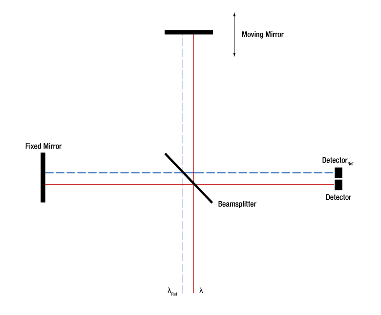
Figure 4.1 Schematic of Internal Michelson Interferometer with Reference Laser
Operating Principle
Figure 4.1 shows a schematic diagram of the scanning Michelson interferometer in the wavelength meter. An input laser of unknown wavelength λ is separated into two paths by a beamsplitter, reflected by a moving or a fixed mirror, recombined by the beamsplitter, and sent to a detector, where an interference pattern is measured as a function of the moving mirror's position. If the mirror travels a distance d and a total of m interference fringes are detected by the detector, then the following holds:

where n(λ) is the index of refraction of the air in the interferometer at the unknown wavelength. A reference laser, with a wavelength of λRef, follows a similar path, but the interference signal is detected on the reference detector, DetectorRef. A similar equation applies to the reference laser, with m → mRef and λ → λRef.
The two equations can be combined and solved for the unknown wavelength, as a function of the measured and known values:

The wavelength meter measures the temperature, pressure, and relative humidity inside the interferometer to calculate the index of refraction of air in the interferometer accurately. In the fast measurement mode, both m and mRef are measured as integers, but in the slow measurement mode, mRef is measured as a fractional number of fringes corresponding to the optical path of the m fringes used for measuring λ.
WM202 Wavelength Meter Front and Back Panels
Click to Enlarge
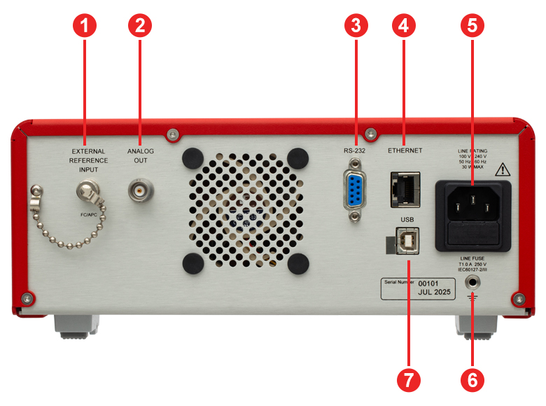
Back Panel

Click to Enlarge
Front Panel
| Back Panel | |
|---|---|
| Callout | Description |
| 1 | External Reference Input: Narrow Key (2.0 mm) FC/APC |
| 2 | BNC Female Wavelength Error Analog Ouput |
| 3 | DE-9 RS232 Connector for Remote Operation |
| 4 | RJ45 Ethernet Connector for Remote Operation |
| 5 | AC Power Cord Connector |
| 6 | 4 mm Banana Socket Ground Terminal |
| 7 | USB 2.0 Type-B Connector for Remote Operation and Transferring Data Saved on the Device to a PC |
| Front Panel | |
|---|---|
| Callout | Description |
| 1 | Power Button |
| 2 | LCD Screen |
| 3 | Five Dynamic Side Menu Buttons |
| 4 | Rotary Navigation and Control Knob |
| 5 | Wide Key (2.2 mm) FC/AFC Input |
Wavelength Meter LCD Screen Views

Click to Enlarge
Figure 6.3 Statistics View: The descriptive statistics of the data collected since the last reset are displayed. The display shows the minimum, maximum, standard deviation, mean, and number of samples, along with the acquisition time, coherence length, and the internal temperature, pressure, and humidity.
Click to Enlarge
Figure 6.2 Long Term View: A graph of the measured wavelength as a function of time is shown and can be recorded to a .csv file. The file can be transfered to a PC through USB transfer.
Click to Enlarge
Figure 6.1 Main View: Diplays the wavelength, estimated input power, and coherence length, with a displayed value and bar graph for the power. The units, averaging, speed, and number of digits displayed can be controlled with the dynamic side menu buttons.
Each Wavelength Meter is Shipped with the Following:
- Wavelength Meter
- USB 2.0 Type-A to Type-B Cable, 2 m Long
- Power Cord, Country Specific, 1.8 m Long
- Quick Reference
- Certificate of Calibration

Click to Enlarge
Figure 7.1 Items Shipped With Each Wavelength Meter
Optical Power Monitor Software for Controlling the Wavelength Meter
Version 6.5
Click the Software button to download the OPM Software.
Software for the Wavelength Meter
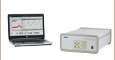
Control with the Optical Power Monitor (OPM) Software
The OPM Software allows for the control of our wavelength meter instruments with a Windows PC. This software GUI provides full control over the instrument, allowing the user to select between Measurement View, Statistics View, and Monitoring View, and set instrument measurement parameters. The software requires a computer running the Windows® 10 or 11 operating system. The OPM software can be used to run the wavelength meter through either a USB or network connection.
Custom Control via SCPI Commands
The wavelength meter device manual lists commands that can also be used to control the wavelength meter for use in custom applications. The commands can be sent from a computer running the Windows® 10 or 11 operating system to the USB, network, or RS-232 port. Descriptions of each command are included in the device manual.
Wavelength Meter Operation Using the OPM Software
Figures 8.1, 8.2, and 8.3 are examples of the OPM software GUI when used to control the WM202 wavelength meter. The Measurement, Statistics, and Monitoring Chart View are summarized below; please see the manual for additional details. When the wavelength meter is connected to the computer and the power is switched on, the software will search for the device, find it, and detect the device's information, such as the device type and serial number.

Click to Enlarge
Figure 8.1 Software Measurement View
The Measurement View for the wavelength meter shows the current wavelength value, the power value, the coherence length value, and the signal on the reference detector. Additionally, the list of active devices is shown in the far left. The device information is available and the device settings can be adjusted, such as Slow/Fast mode, Internal/External reference laser, analog output, and wavelength calibration.

Click to Enlarge
Figure 8.2 Software Statistics View
Next to the Measurement View, the Statistics View displays the descriptive statistics of the wavelength meter measurement data on a rolling buffer and shows a bar graph of measurement values. You can start, pause, or stop data collection and adjust the aquisition time or number of samples by clicking on the cogwheel in the top left corner of the Statistics View.
Click to Enlarge
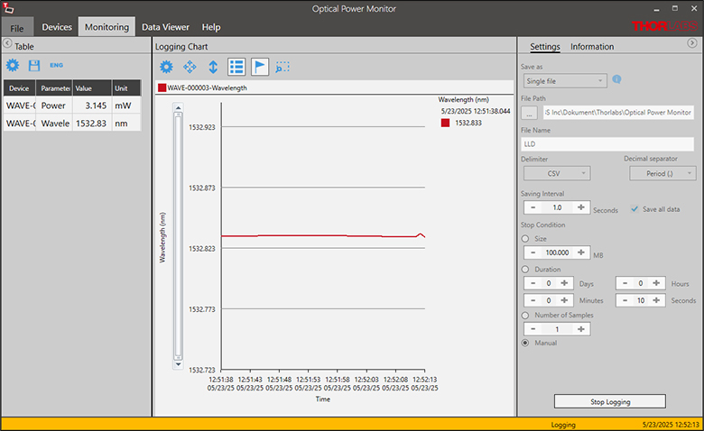
Figure 8.3 Software Monitoring Chart View
The Monitoring Chart view allows the wavelength meter measurements to be recorded to a .csv file over time and displays the data in a graph. The interval between saves and filepath are set by the user. The user can also configure various stopping conditions for when the data will no longer be saved to the file.

Click to Enlarge
Figure 8.4 Web Viewer for Wavelength Meter
If the wavelength meter is connected to the network, the current wavelength, power, and coherence length can be displayed in any web browser by navigating to the configured IP address for the device. No settings or configurations can be modified in the web viewer. The wavelength units and number of digits will be the same as shown on the touch screen in direct operation.
| Posted Comments: | |
| No Comments Posted |

 Zoom
Zoom
Click to Enlarge
Figure G1.1 The measurement absolute accuracy in wavelength and frequency are graphed, for reference. The graph corresponds to the 1 ppm accuracy specified when using the internal reference after 15 minute warm-up, if the instrument is calibrated annually.
- 600 to 1700 nm Wavelength Meter With Accuracy as Low as 0.3 ppm
- Simultaneously Measure the Wavelength, Coherence Length, and Power of a CW Laser with Bandwidth ≤10 GHz
- Control the Device through the Touchscreen Interface, Thorlabs' Software, or SCPI Commands
The WM202 Wavelength Meter measures the wavelength, coherence length, and power of a CW laser that is coupled to the device through an FC/APC input fiber by using a scanning Michelson interferometer and a reference laser. The wavelength measurement absolute accuracy is 1 ppm when using the internal reference laser, or 0.3 ppm when using an external reference laser with ±25 MHz accuracy (after a 15-minute warm-up, if the device is calibrated annually with a known wavelength laser). The annual calibration can be performed by the user if an appropriate laser is available (see the Specs tab for details), or by Thorlabs, if needed, by ordering Item #
The wavelength meter can be controlled using the device interface, Thorlabs' Optical Power Monitor (OPM) Software (USB or network connection), or SCPI commands (USB, network, or RS-232 connection). The wavelength, power, and coherence length measurements can also be monitored from a web viewer within a local area network. Please see the Software tab for more information.

 Zoom
Zoom- LLD1530 Frequency-Locked Laser System Based on Distributed Feedback (DFB) Laser
- Locked Using a NIST-Traceable Transition of Acetylene (C2H2)
- Vacuum Wavelength of 1532.8323 nm With Absolute Accuracy at Start-Up Better Than ±25 MHz
- Provides a Known Wavelength External Reference Laser or Calibration Laser for the WM202 Wavelength Meter
- TD1315R5A1 50:50 Coupler Allows the LLD1530 Laser to be Used as the External Reference and Calibration Laser for the WM202 Wavelength Meter
The LLD1530 Frequency-Locked Laser at 1532.8323 nm has an absolute accuracy at start-up that is better than ±25 MHz and a maximum output power of 10 mW. The LLD1530 laser frequency is actively stabilized using a National Institute of Standards and Technology (NIST)-traceable molecular transition of C2H2, allowing it to be an appropriate known wavelength external reference laser for the WM202 Wavelength Meter. If the LLD1530 laser is purchased with the WM202 Wavelength Meter, the wavelength meter can be shipped calibrated with the LLD1530 laser as the external reference; please contact tech sales to make this request.
The required annual calibration of the WM202 wavelength meter can be performed using the LLD1530 laser as both the external reference laser and the calibration laser by splitting the beam into two fibers using a fiber optic coupler, such as the TD1315R5A1 1x2 SM Coupler, and connecting it to both the external reference (rear) and input (front) ports.
Please see the full web presentation for the LLD1530 frequency-locked laser for more details.
Thorlabs offers a factory calibration service for our Wavelength Meter. To ensure measurements within the specified accuracy, we recommend recalibrating your wavelength meter once a year. For more information, please contact Tech Support.
Requesting a Calibration
Thorlabs provides two options for requesting a calibration:
- Complete the Returns Material Authorization (RMA) form. When completing the RMA form, please enter your name, contact information, the Part #, and the Serial # of the item being returned for calibration; in the Reason for Return field, select "I would like an item to be calibrated." All other fields are optional. Once the form has been submitted, a member of our RMA team will reach out to provide an RMA Number, return instructions, and to verify billing and payment information.
- Enter the Part # and Serial # of the wavelength meter that requires recalibration below, and then click "Add to Cart". A member of our RMA team will reach out to coordinate the return of the item for calibration. Should you have other items in your cart, note that the calibration request will be split off from your order for RMA processing.
Please Note: To ensure your item being returned for calibration is routed appropriately once it arrives at our facility, please do not ship it prior to being provided an RMA Number and return instructions by a member of our team.