 Products Home / Optogenetics / Implantable Fiber Optic Cannulae / Implantable Fiber Optic Cannulae, Ø400 µm Core, 0.39 NA Fiber
Implantable Fiber Optic Cannulae, Ø400 µm Core, 0.39 NA Fiber
- Cannulae with Ø400 µm Core, 0.39 NA Multimode Fiber
- Multiple Ferrule Size and Material Options
- 2 mm to 20 mm Cleaved or 50 mm Uncleaved Fiber
- Custom Versions Available
CFMLC14U-20
50 mm Uncleaved Fiber, Pack of 20
CFMC14L10
10 mm Cleaved Fiber
CFM14L05
5 mm Cleaved Fiber
CFMLC14L02
2 mm Cleaved Fiber
Stainless Steel
Ø1.25 mm
Ø2.5 mm
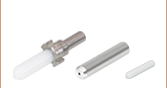
Polished Ceramic
Ferrule Ends
Both Stainless Steel and Ceramic Ferrules are Available in Ø1.25 mm and Ø2.5 mm Sizes
CFML14L20
20 mm Cleaved Fiber


Please Wait
| Fiber Optic Cannula Selection Guide |
|---|
| Ø105 µm Core, 0.22 NA Fiber |
| Ø200 µm Core, 0.22 NA Fiber |
| Ø200 µm Core, 0.39 NA Fiber |
| Ø200 µm Core, 0.50 NA Fiber |
| Ø300 µm Core, 0.39 NA Fiber |
| Ø400 µm Core, 0.39 NA Fiber |
| Ø400 µm Core, 0.50 NA Fiber |
| Dual-Core Cannula |
| Cannulae with Diffuser Tip |
| Cannula Fiber Specifications | |
|---|---|
| Fiber Type | FT400EMT |
| Wavelength Range (Click for Plot) |
400 - 2200 nm |
| Fiber Core Diameter | 400 ± 8 µm |
| Fiber Outer Diameter | 425 ± 10 μm |
| Numerical Aperture | 0.39 |
| Cleaved Length Tolerance | ±0.5 mm |
Click for Details
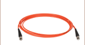
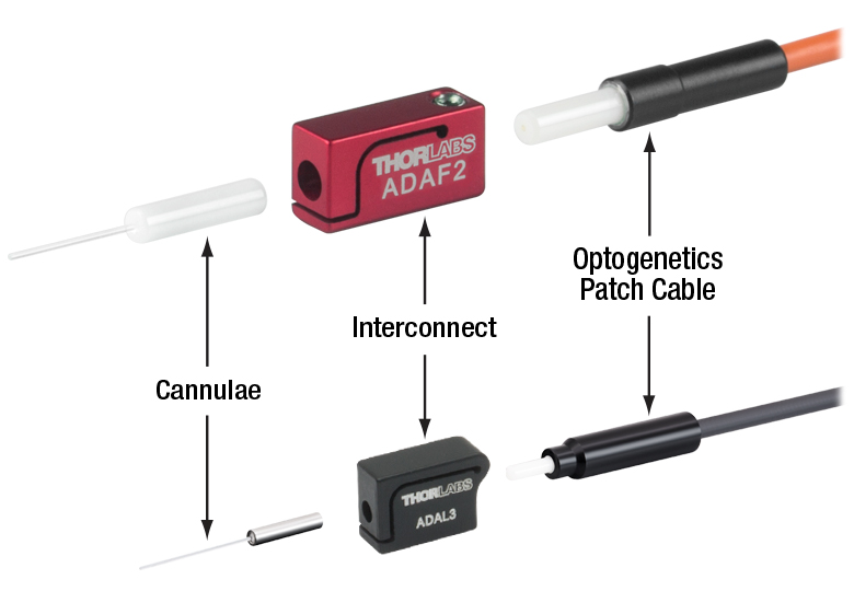
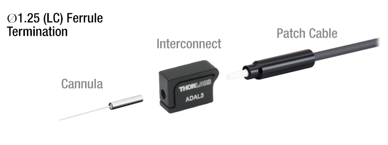
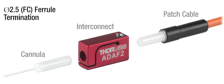
Figure 1.1 All Fiber Optic Cannulae and Optogenetics Patch Cables can be easily mated using an Interconnect or Mating Sleeve.
Features
- Ø400 µm Core, 0.39 NA Fiber Optic Cannulae
- Multiple Ferrule Options
- Ø1.25 mm (LC) or Ø2.5 mm (FC) Size
- Stainless Steel or Ceramic (Zirconia) Material
- Flat Cleaved Cannulae Available with Fiber 2, 5, 10, or 20 mm Long
- Uncleaved Cannulae Available with Fiber 50 mm Long
- Custom Versions Available (See Custom Cannula Tab for Details)
- Contact Tech Support for Discount on High-Volume Purchases
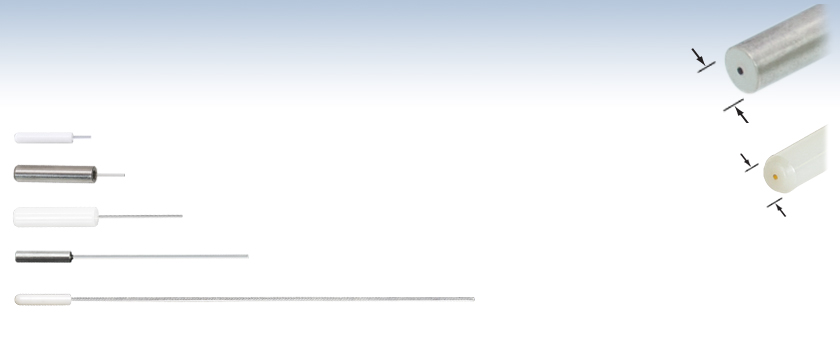
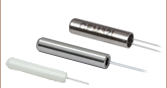
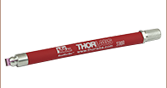
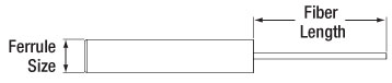
Thorlabs' Implantable Fiber Optic Cannulae are designed to deliver light from an LED or laser light source to optically sensitive cells within a specimen. Each cannula consists of a ferrule and a length of protruding optical fiber that is typically surgically implanted using stereotaxic guidance. After implantation, the ferrule remains exposed; this provides an interface with our line of Optogenetics Equipment (see the OG Selection Guide tab for a full listing).
The cannulae sold on this page use Ø400 µm core, 0.39 NA fiber (Item # FT400EMT) with a variety of ferrule and length options. Cannulae with Ø1.25 mm (LC) ferrules are less invasive and lightweight, making them ideal for smaller specimens or placing multiple cannulae in close proximity. Ø2.5 mm (FC) ferrules are larger and easier to handle; this provides a more robust connection that is ideal for working with larger specimens. Stainless steel ferrules are easy to score for better adherence when implanted and fixed with glue, while ceramic ferrules are lighter for reduced stress on the specimen.
Cannulae are available with ready-to-use flat cleaved fiber of a pre-determined length (2, 5, 10, or 20 mm). Uncleaved cannulae with 50 mm scissor-cut fiber can be cleaved by the user to a desired length using the procedure outlined on the Cannula Cleaving tab. Implant guides for the cannulae sold on this page are also available below in packs of one or five.
Each cannula includes a protective cap that shields the ferrule end from dust and other hazards. Additional fiber caps are also sold separately. If the ferrule end becomes dirty from use, we offer a selection of inspection tools, as well as fiber optic cleaning products.
Patch Cable Compatibility and Numerical Aperture (NA)
For best performance, choose a patch cable and cannula with the same fiber core diameter and NA. Mixing stainless steel and ceramic ferrules should not introduce significant additional signal losses. Numerical Aperture (NA) defines the angle of the cone of light leaving the fiber tip at the end of the cannula and is a dimensionless quantity used by fiber manufacturers to specify the acceptance angle of an optical fiber. Cannulae with a lower NA provide a narrower cone of light at the tip, resulting in higher light intensity over a smaller area, while cannulae with a higher NA generate a wider cone of light that illuminates a larger area with lower intensity.
Click to Enlarge
Figure 1.2 Multiple fiber NAs are available across our optogenetics product line; cannulae with a 0.39 NA are sold on this page.
Mating Sleeve Compatibility
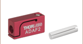
The ferrule diameter of a patch cable and cannula is the key factor for physical compatibility with an interconnect and mating sleeve. Cannulae and patch cables using Ø1.25 mm (LC) ferrules can be connected using the ADAL1 mating sleeve or ADAL3 interconnect. Patch cables and cannulae using Ø2.5 mm (FC) ferrules are compatible with the ADAF1 mating sleeve and ADAF2 interconnect.
Custom Cannulae
Thorlabs also manufactures custom fiber optic cannulae. We can provide different fiber and/or ferrule types as well as different fiber lengths. Please see the Custom Cannula tab for details.
Optogenetics Product Family for In Vivo Applications
Thorlabs offers a wide variety of products designed to support in vivo optogenetics applications. Please visit the OG Selection Guide tab to see a full listing of available products for different applications.

| Related Optogenetics Products | |||||||||
|---|---|---|---|---|---|---|---|---|---|
| Light Sources | Patch Cables (Ø400 µm Core, 0.39 NA) | Mating | Cannulae (Ø400 µm Core, 0.39 NA) | Accessories | |||||
| Fiber-Coupled LEDs | MM Laser, 473 nm | Standard | Rotary Joint | Bifurcated Y-Cables | Interconnects | Mating Sleeves | Standard | Implant Guides | Cannula Holders |
Custom Fiber Optic Cannula
Thorlabs offers custom cannulae with the following options. Place a quote request through the following form to receive a quote for your custom cannula order.
Fiber Cleaving
A cleave, or precision cut, is used to ensure proper light propagation out of the fiber tip. Thorlabs' uncleaved cannula must be cleaved before use; a cleaved cannula can be cleaved again if a shorter fiber length is desired. We recommend the following procedure for cleaving the fiber end.
Required Materials
- Uncleaved Fiber Optic Cannula
- S90R Fiber Scribe
- BFG1 Bare Fiber Gripper
- KW32 Kimwipes™ Lint-Free Wipes
- Isopropyl Alcohol
- JEL10 Eye Loupe, EYL10X Premium Eye Loupe, or Microscope
- FTDU Fiber Optic Disposal Unit (Recommended)
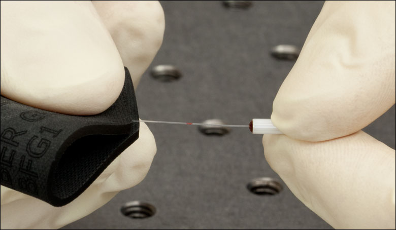
Cleaving Procedure
- Clean the fiber end of the cannula using a lint-free wipe and isopropyl alcohol. Do not use acetone, as this will damage the TECS cladding on the exposed fiber.
- Measure the desired length of fiber from the end of the ferrule. Mark this length on the fiber with a marker.
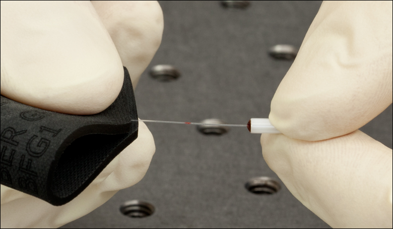
- Place the cannula on a hard surface and secure the fiber end with a finger or tape, as shown in Figure 18A.
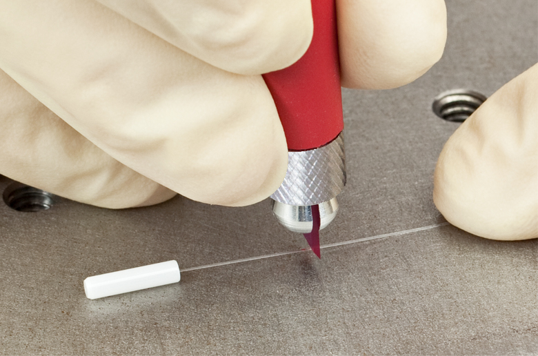
- Hold the cleaving tool perpendicular to the fiber and gently score the fiber as shown in Figure 18A. Do not apply excessive pressure. The fiber should not break off at this point.
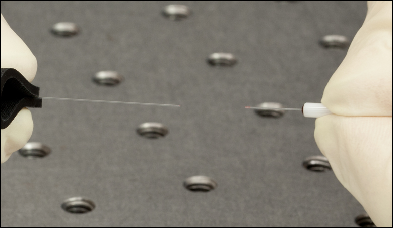
This step is critical in obtaining a good cleave. If the scribe is made too hard, the fiber will break instead of cleaving. If the scribe is too light, the fiber will not cleave. - Hold the cannula in one hand, and grip the fiber end with a bare fiber gripper in the other end as shown in Figure 18B. Pull the fiber straight back until the fiber cleaves as shown in Figure 18C. Dispose of the scrap fiber end in the FTDU or any medical or fiber sharps container.
- If the fiber does not break with a moderate amount of tension, repeat steps 4-5 above applying slightly more pressure when scoring. Inspect the cleave using an eye loupe or microscope.
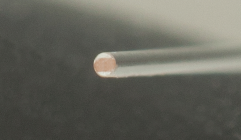
A good cleave will be flat across the fiber and perpendicular to the optic axis. There should be no ‘tag’ (i.e., protrusion) from the edge of the fiber. The region where the initial scribe was made may be visible. It should be less than 5% of the core diameter. Be patient as this process takes a little practice. Please be aware that it will be more difficult to achieve a high-quality cleave in large-core-diameter fibers compared to thinner fibers. A view of a properly cleaved fiber end as seen through a Thorlabs' JEL10 eye loupe is shown in Figure 18D.
Click Here for a PowerPoint Illustrating This Procedure
Thorlabs also offers a full fiber connectorization manual, which covers fiber termination and connectorization, as well as bare fiber cleaving. It can be downloaded for free here, or a paper copy can be purchased here.
| Posted Comments: | |
schlegel
(posted 2013-10-21 17:29:24.423) Are ceramic ferrules available where both ends are polished, i.e. the fiber is L=0mm on the cannula end? pbui
(posted 2013-10-24 10:49:00.0) Response from Phong at Thorlabs: Yes, we should be able to provide a custom polished ferrule as per your request. We will contact you to discuss the details further. tcohen
(posted 2012-11-13 02:35:09.323) Response from Tim at Thorlabs: Thank you for contacting us. We are looking into developing fibers in our drawing towers that have a thicker layer of Tefzel buffer to absorb any light escaping from the cladding. For use in a cannula where the buffer would be stripped we are also looking at designs involving more dopant or increased cladding thicknesses. user
(posted 2012-10-15 09:18:47.19) Do you have a cannula blocking traveling light in clad mode? |
| Quick Links | |||
|---|---|---|---|
| Single-Site Stimulation | |||
| One Light Source to One Cannula Implant | |||
| Multilateral Stimulation | |||
| One Light Source to Two Cannula Implants Using Rotary Joint Splitter | |||
| One or Two Light Sources to Two Cannula Implants | |||
| One Light Source to Seven Cannula Implants | |||
| Two Light Sources into One Dual-Core Cannula Implant | |||
| Illumination | |||
| Fiber-Coupled LEDs and Drivers | |||
Optogenetics Selection Guide
Thorlabs offers a wide range of optogenetics components; the compatibility of these products in select standard configurations is discussed in detail here. Please contact Technical Support for assistance with items outside the scope of this guide, including custom fiber components for optogenetics.
Single-Site Stimulation
One Light Source to One Cannula Implant
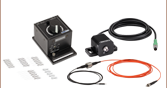
The most straightforward method for in vivo light stimulation of a specimen is to use a single fiber optic with a single LED light source. The single wavelength LED is powered by an LED driver, and then the illumination output is fiber-coupled into a patch cable, which connects to the implanted cannula. See the expandable compatibility tables for the necessary patch cables and cannulae to create this setup. To choose the appropriate LED and driver, see below or the full web presentation.
Click on Each Component for More Information
Click to See Ø1.25 mm (LC) Ferrule Compatible Patch Cables, Cannulae, and Interconnects
Click to See Ø2.5 mm (FC) Ferrule Compatible Patch Cables, Cannulae, and Interconnects
Multilateral Stimulation
The ability to accurately and simultaneously direct light to multiple locations within a specimen is desired for many types of optogenetics experiments. For example, bilateral stimulation techniques typically target neurons in two spatially separated regions in order to induce a desired behavior. In more complex experiments involving the simultaneous inhibition and stimulation of neurons, delivering light of two different monochromatic wavelengths within close proximity enables the user to perform these experiments without implanting multiple cannulae, which can increase stress on the specimen.
Multilateral stimulation can be achieved with several different configurations depending on the application requirements. The sections below illustrate examples of different configurations using Thorlabs' optogenetics products.
Option 1: One Light Source to Two Cannula Implants Using Rotary Joint Splitter
Thorlabs' RJ2 1x2 Rotary Joint Splitter is designed for optogenetics applications and is used to split light from a single input evenly between two outputs. The rotary joint interface allows connected patch cables to freely rotate, reducing the risk of fiber damage caused by a moving specimen. See the expandable compatibility table for the necessary cables and cannulae to create this setup. For LEDs and drivers, see below or the full web presentation.
Click to See Ø1.25 mm (LC) Ferrule Components Recommended for Use with RJ2 Rotary Joint Splitter
Click to See Ø2.5 mm (FC) Ferrule Components Recommended for Use with RJ2 Rotary Joint Splitter
Option 2: One or Two Light Sources to Two Cannula Implants
If the intent is for one LED source to connect to two cannulae for simultaneous light modulation, then a bifurcated fiber bundle can be used to split the light from the LED into each respective cannula. For dual wavelength stimulation (mixing two wavelengths in a single cannula) or a more controlled split ratio between cannula, one can use a multimode coupler to connect one or two LEDs to the cannulae. If one cable end is left unused, the spare coupler cable end may be terminated by a light trap. See the expandable compatibility table for the necessary cables and cannulae to create this setup. For LEDs and drivers, see below or the full web presentation.
Click on Each Component for More Information
Option 3: One Light Sources to Seven Cannula Implants
If the intent is for one LED source to connect to seven cannulae for simultaneous light modulation, then a 1-to-7 fiber bundle can be used to split the light from the LED into each respective cannula. See the expandable compatibility table for the necessary cables and cannulae to create this setup. For LEDs and drivers, see below or the full web presentation.
Click on Each Component for More Information
Two Light Sources into One Dual-Core Cannula Implant
For bilateral stimulation applications where the two cannulas need to be placed in close proximity (within ~1 mm), Thorlabs offers dual-core patch cables and cannulae that are designed for this specific application. Each core is driven by a separate light source, enabling users to stimulate and/or supress nerve cells in the same region of the specimen. See the expandable compatibility table for the necessary cables and cannulae to create this setup. For LEDs and drivers, see below or the full web presentation.
Click on Each Component for More Information
| Part Selection Table (Click Links for Item Description Popup) | |||||||||
|---|---|---|---|---|---|---|---|---|---|
| Common Fiber Properties | |||||||||
| Core Diameter | 200 µm | ||||||||
| Wavelength Range | 400 - 2200 nm | ||||||||
| NA | 0.39 | ||||||||
| Fiber Type | FT200EMT | ||||||||
| Ferrule Stylea | FC (Ø2.5 mm) | ||||||||
| Dual-Core Patch Cable | FC/PC Input | BFY32FL1 | |||||||
| SMA905 Input | BFY32SL1 | ||||||||
| Compatible Mating Sleeve/Interconnect | ADAF1 ADAF2 ADAF4-5 |
||||||||
| Dual-Core Fiber Optic Cannulaec | Stainless Steel | CFM32L10 CFM32L20 |
|||||||
| Table 93A Fiber-Coupled LEDs for Optogenetics | ||||
|---|---|---|---|---|
| LED Item # | Wavelengtha | Typical Opsin | Output Powerb | Color |
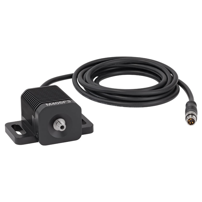
| M405F3c | 405 nm | mmilCFP, hcriGFP | 3.7 mW | UV |
| M430F1 | 430 nm | ChR2 | 7.5 mW | Violet |
| M455F3 | 455 nm | ChIEF, bPAC | 24.5 mW | Royal Blue |
| M470F4 | 470 nm | ChR2, ChR2-SFO | 20 mW | Blue |
| M490F4 | 490 nm | Rh-CT, ChR2 (E123A) | 2.8 mW | Blue |
| M505F3 | 505 nm | ChRGR, Opto-α1AR, Opto-β2AR | 11.7 mW | Cyan |
| M530F3 | 530 nm | C1V1, VChR1 | 9.6 mW | Green |
| M565F3 | 565 nm | Arch, VChR1-SFO | 13.5 mW | Lime |
| M595F2 | 595 nm | ChR2-SFO, eNpHR3.0 | 11.5 mW | Amber |
| M625F2 | 625 nm | ReChR | 17.5 mW | Red |
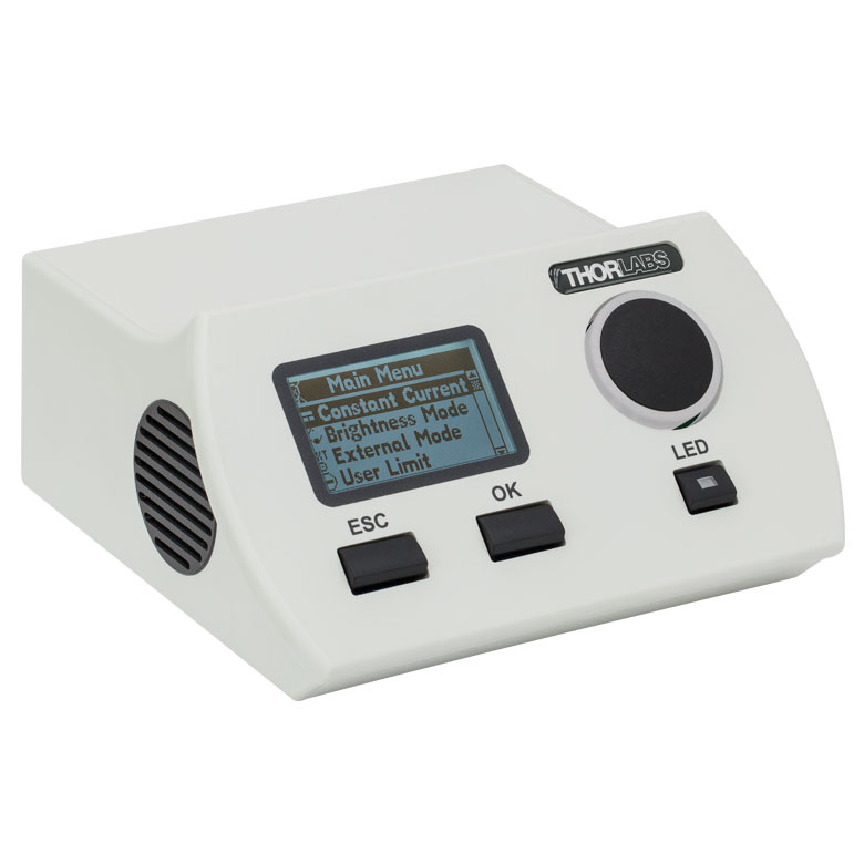
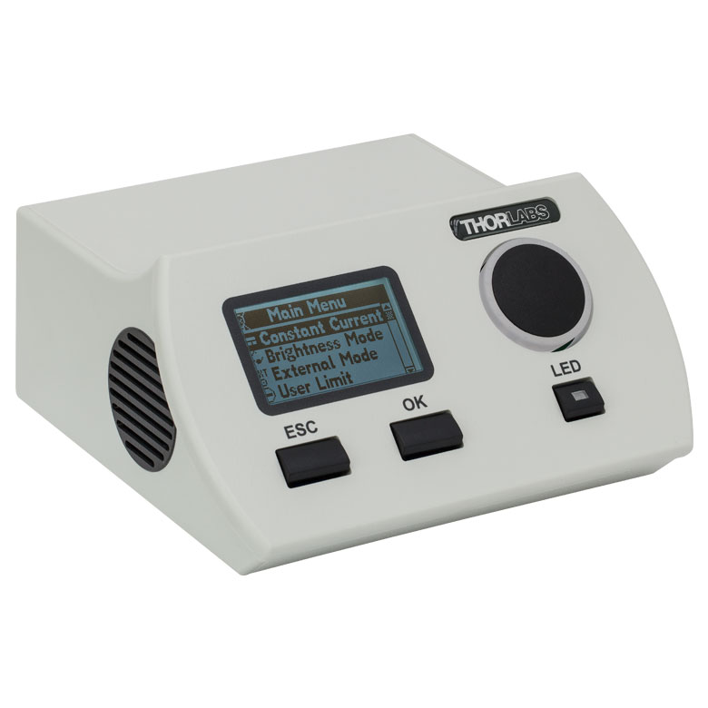
Illumination
Fiber-Coupled LEDs and Drivers
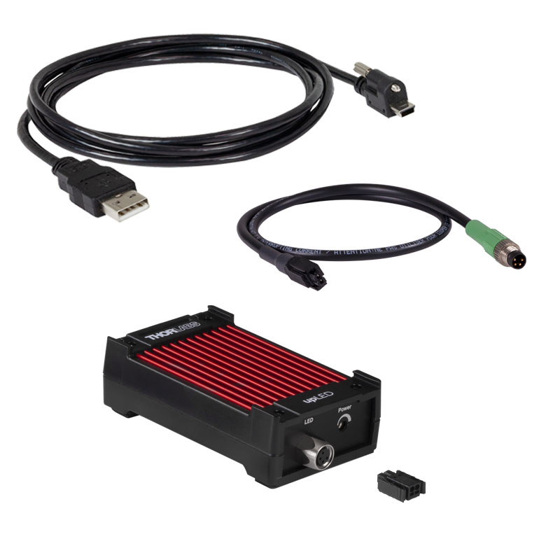
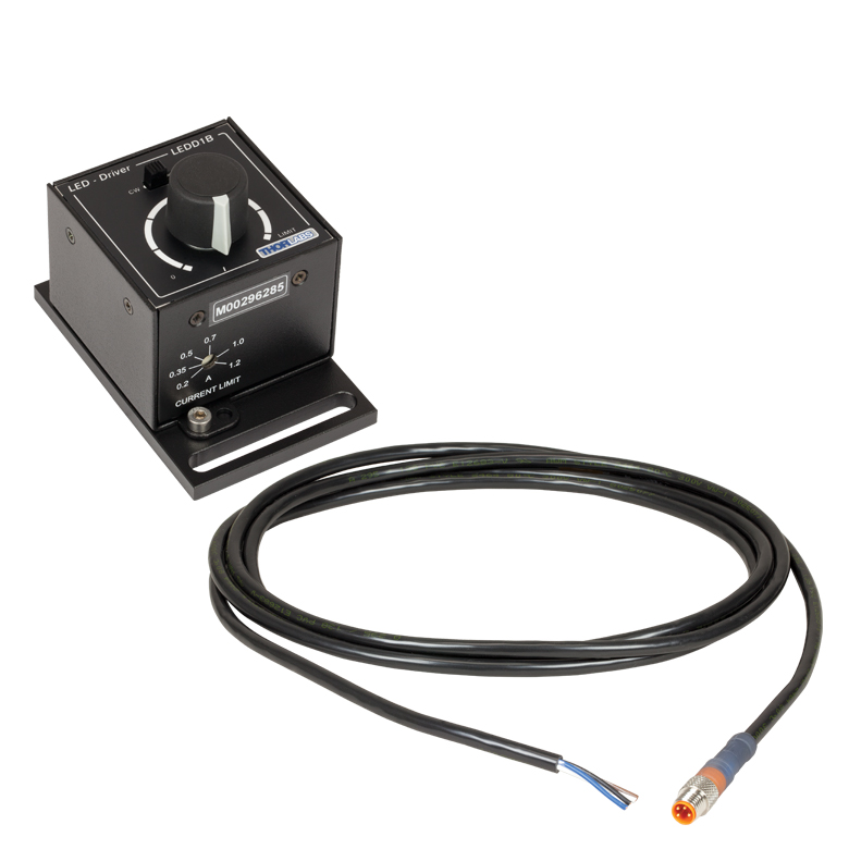
Our fiber-coupled LEDs are ideal light sources for optogenetics applications. They feature a variety of wavelength choices and a convenient interconnection to optogenetics patch cables. Thorlabs offers fiber-coupled LEDs with nominal wavelengths ranging from 280 nm to 1050 nm. See Table 93A for the LEDs with the most popular wavelengths for optogenetics. See the expandable table for a list of compatible LED drivers.

| Item # Prefix |
Image | Ferrule Size | Ferrule Length |
Ferrule Material |
Fiber Length | Fiber Finish | Compatible Interconnect / Sleeve |
Compatible Patch Cables |
Compatible Implant Guidea |
|---|---|---|---|---|---|---|---|---|---|
| CFMLC14 | Ø1.25 mm (LC) | 6.4 mm | Ceramic | 2, 5, 10, or 20 mm | Flat Cleave | ADAL3 Interconnect ADAL1 Mating Sleeve |
Standard: M99 and M98 Rotary Joint: RJPFL4 and PJPSL4 Bifurcated: BFYL4LS01 and BFYL4LF01 |
OGL | |
| CFMLC14U | 50 mm | Scissor Cut |
| Item # Prefix |
Image | Ferrule Size | Ferrule Length |
Ferrule Material |
Fiber Length | Fiber Finish | Compatible Interconnect / Sleeve |
Compatible Patch Cables |
Compatible Implant Guidea |
|---|---|---|---|---|---|---|---|---|---|
| CFML14 | Ø1.25 mm (LC) | 6.4 mm | Stainless Steel | 2, 5, 10, or 20 mm | Flat Cleave | ADAL3 Interconnect ADAL1 Mating Sleeve |
Standard: M99 and M98 Rotary Joint: RJPFL4 and PJPSL4 Bifurcated: BFYL4LS01 and BFYL4LF01 |
OGL | |
| CFML14U | 50 mm | Scissor Cut |
| Item # Prefix |
Image | Ferrule Size | Ferrule Length |
Ferrule Material |
Fiber Length | Fiber Finish | Compatible Interconnect / Sleeve |
Compatible Patch Cables |
Compatible Implant Guidea |
|---|---|---|---|---|---|---|---|---|---|
| CFMC14 | Ø2.5 mm (FC) | 10.5 mm | Ceramic | 2, 5, 10, or 20 mm | Flat Cleave | ADAF2 Interconnect ADAF1 Mating Sleeve |
Standard: M82 and M79 Rotary Joint: RJPFF4 anf RJPSF4 Bifurcated: BFYF4LS01 and BFYF4LF01 |
OGF | |
| CFMC14U | 50 mm | Scissor Cut |
| Item # Prefix |
Image | Ferrule Size | Ferrule Length |
Ferrule Material |
Fiber Length | Fiber Finish | Compatible Interconnect / Sleeve |
Compatible Patch Cables |
Compatible Implant Guidea |
|---|---|---|---|---|---|---|---|---|---|
| CFM14 | Ø2.5 mm (FC) | 12.7 mm | Stainless Steel | 2, 5, 10, or 20 mm | Flat Cleave | ADAF2 Interconnect ADAF1 Mating Sleeve |
Standard: M82 and M79 Rotary Joint: RJPFF4 anf RJPSF4 Bifurcated: BFYF4LS01 and BFYF4LF01 |
OGF | |
| CFM14U | 50 mm | Scissor Cut |

 Zoom
Zoom
Click for Details
Figure 630C Cross Section Drawing of OGL with CFML22L05 Cannula (Not Included)
Click for Details
Figure 630B Implant Guide Assembly
Click for Details
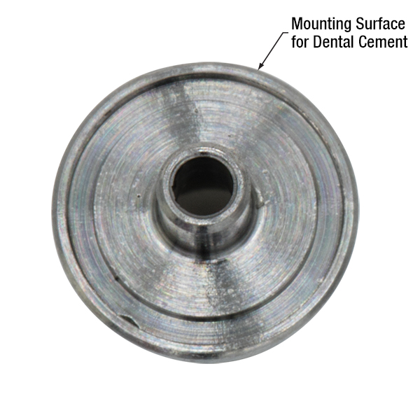
Figure 630A Mounting Surface of OGF Cannula Impant Guide
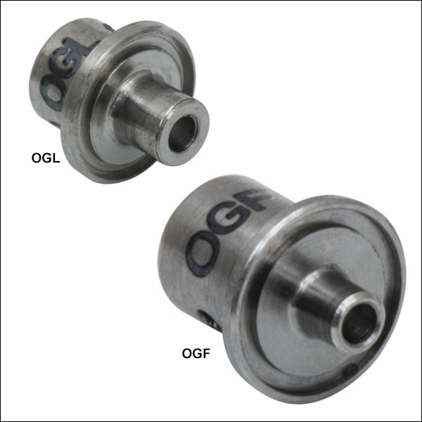
- Improves Adhesion and Stability During Implantation
- Compatible with Ø1.25 mm and Ø2.5 mm Fiber Optic Cannulae with ≥5 mm Length
- Ø3.8 mm (OGL) or Ø5.1 mm (OGF) Mounting Surface with Grooved Ring for Dental Cement
- Lightweight Surgical Titanium Construction (≤0.11 g)
- Weep Holes for Glue and Epoxy to Secure a Cannula
- Compatible with Stereotaxic Cannula Holders
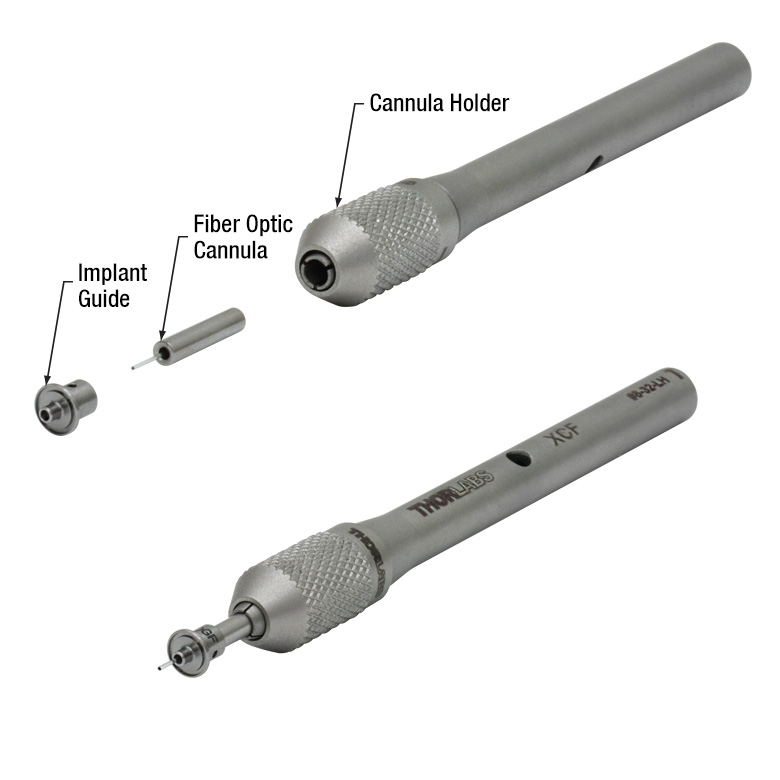
These Cannula Implant Guides are designed to provide guidance and stability for a fiber optic cannula during an implantation procedure. The bottom surface of each implant guide features a roughened surface and circular groove (see Figure 630A) that increases the surface area available to dental cement and improves adhesion to the specimen. A 1.6 mm long protrusion on the implant guide helps stabilize the guide when implanted. Each implant is constructed using lightweight surgical titanium (≤0.11 g) which can be sterilized prior to use. For convenience, the cannula guides are offered below in packs of one or five.
For best results when implanting a cannula, the OGL and OGF should be used with a cannula holder and stereotaxic guidance equipment. To affix the cannula within the implant guide, first insert the cannula into the receptacle of the implant guide (see Figure 630C). Then, add a small amount of cement or epoxy to the cannula via the two Ø0.8 mm weep holes. Finally, attach the cannula ferrule to an XCL (Ø1.25 mm ferrule) or XCF (Ø2.5 mm ferrule) cannula holder.
The OGL implant guide is compatible with our standard Ø1.25 mm cannulae (ceramic and stainless steel) and the OGF implant guide is compatible with our standard Ø2.5 mm cannulae (ceramic and stainless steel). When assembled, the length of the protruding fiber is reduced by 2 mm; therefore, these implant guides cannot be used with our 2 mm long cannulae. Additionally, due to the fiber separation distance, the implant guides cannot be used with our dual-core cannulae.