 Products Home
Fiber Optic Rotary Joint Patch Cables for Optogenetics
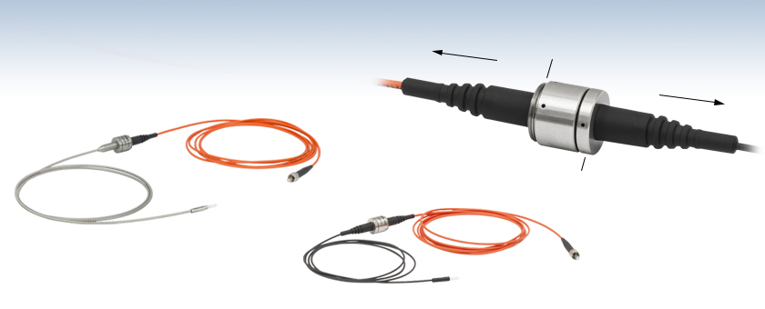
- Prevents Fiber Damage from Specimen Movement
- Ø1.25 mm or Ø2.5 mm Ceramic Ferrule on One End
- Versions for Ø200 µm or Ø400 µm Core Cannulae
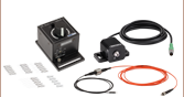
Rotary Joint Detail
SM05 Mounting Threads
To Specimen
To Light Source
Rotating Section
Integrated Rotary Joint
Prevents Fiber Damage
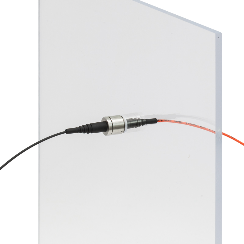
Ø2.5 mm Ferrule End
SMA Connector
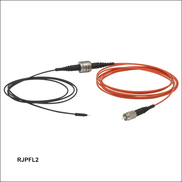
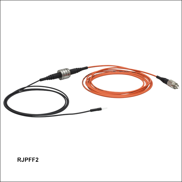
RJPSF2
RJASF2
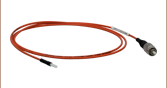
Stainless Steel Tubing and Sleeves Prevent Damage from Specimen
Lightweight Heat-Shrink Tubing Minimizes Pressure on Specimen


Please Wait
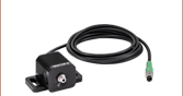
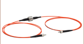
Rotary Joint Patch Cable Features
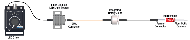
Our articulated patch cables provide a complete fiber optic solution, connecting to the light source on one end and the implanted cannula on the other.
Click to Enlarge
SMA (Shown) or FC/PC Connector Connects to LED (Shown) or Laser Light Sources, Respectively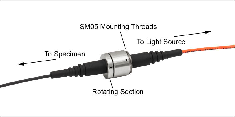
Click for Details
Rotary Joint Prevents Tangling and Damage to Optical Fiber from Specimen Movement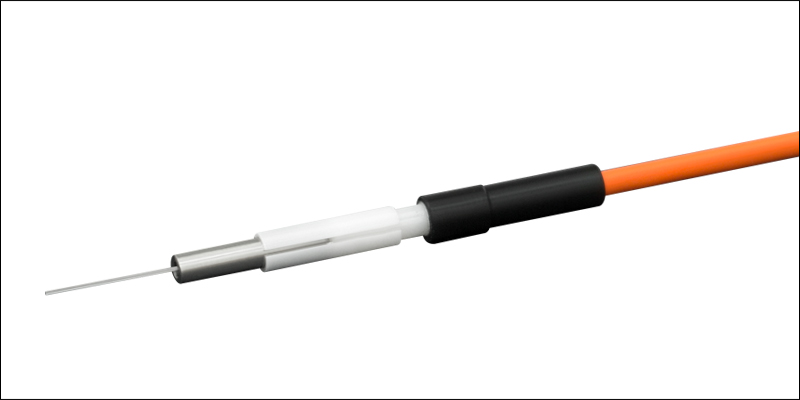
Click to Enlarge
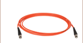
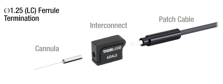
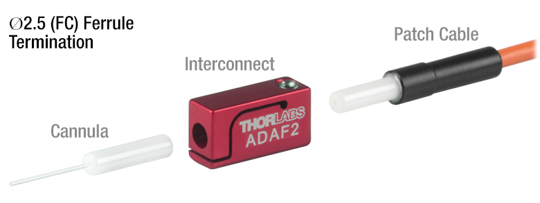
Ø1.25 mm or Ø2.5 mm (Shown) Ferrule End Connects to Implanted Fiber Optic Cannula using a ADAF1 Mating Sleeve
Features
- Articulated Rotary Joint Protects Against Fiber Damage Caused by Moving Specimen
- Integrated 0.39 NA, Ø200 µm or Ø400 µm Core Patch Cables
- Single Cable Connection Between Cannula and Light Source
- Available with FC/PC or SMA Connector and Ø1.25 mm or Ø2.5 mm Ferrule End
- Metal Bearings Provide Extremely Smooth Rotation
- Ø200 µm Core Patch Cables with Ø2.5 mm Ferrule End are Available with Stainless Steel Tubing
- SM05-Threaded Housing for Secure Mounting
Integrated Design
Our articulated rotary joint patch cables, also known as commutators, are a one-piece solution for optogenetics experiments. The built-in rotary joint interface allows the cable to freely rotate, reducing the risk of damage in optogenetics experiments. Rather than using two fiber patch cables with a separate rotary joint interface, the permanently attached fiber optics directly connect to the light source on one end and the specimen implant on the other. The lens-free design allows the rotary joint to operate over a wide wavelength range.
For a rotary joint interface with removable patch cables, Thorlabs offers the RJ1 1x1 Rotary Joint for FC/PC Multimode Patch Cables. This rotary joint operates over a 400 nm to 700 nm wavelength range, and with FC/PC ports, fibers can be selected with specific cores, NAs, and jacketing types to optimize an experiment.
Rotary Joint
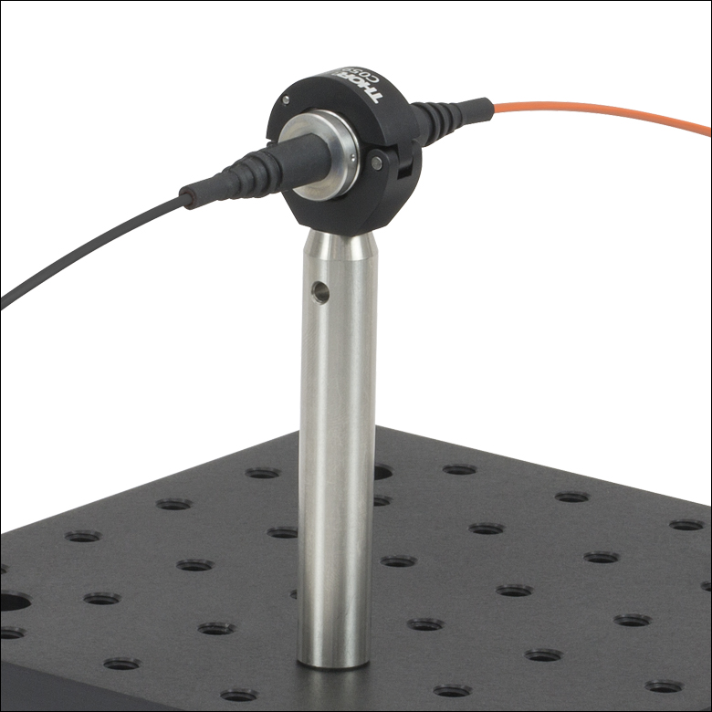
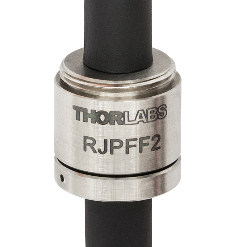
The rotary joint is precision machined and has sealed metal bearings for extremely smooth rotation, long lifetime, and low signal strength variations as the joint rotates. The rotary joint features an external SM05 (0.535"-40) mounting thread for compatibility with our Ø1/2" optic mounts. The Ø0.59" body of the joint can also be quickly mounted using our C059TC clamp, allowing drop-in installation of these cables. See the Mounting Options tab for examples of mounts constructed with Thorlabs' optomechanics equipment.
Fiber Optics
The permanently attached fiber optic leads are designed to provide a complete optogenetics solution for connecting a light source to an implanted fiber optic cannula. They are built with FT200EMT Ø200 µm core or FT400EMT Ø400 µm core, 0.39 NA fiber. 2 m of fiber is on the light source side of the rotary joint, and 1 m is on the specimen side. The fiber on the light source side of the rotary joint includes standard FT020 orange tubing, while the specimen side is protected by either lightweight black tubing, which minimizes cable mass, or stainless steel tubing, which protects the fiber from the specimen. Models are available with Ø1.25 mm or Ø2.5 mm ferrule ends for cannula interconnection. Choose from an FC/PC or SMA connector for compatibility with all of Thorlabs' optogenetics light sources.
Each rotary joint cable includes two protective caps that shield the ferrule ends from dust
and other hazards. Additional CAPF Fiber Caps for FC/PC-terminated and Ø2.5 mm ferrule ends, CAPM Rubber Caps for SMA-terminated ends, and CAPL Fiber Caps for Ø1.25 mm ferrule ends are also sold separately.
Ferrule Size and Fiber Core Size
Our rotary joint patch cables have either a Ø1.25 mm or Ø2.5 mm ceramic ferrule end. Using a lightweight, compact Ø1.25 µm (LC) ferrule minimizes stress on the specimen and offer the ability to implant several cannulae near the same location for applications such as bilateral stimulation. A Ø2.5 mm ferrule end provides easier handling and a more robust connection to the specimen. Smaller fiber core sizes, such as Ø200 µm, are less invasive, making them ideal for smaller specimens. Larger core sizes, such as Ø400 µm, offer a more robust solution for larger specimens, as well as higher power light sources.
Cannula and Component Compatibility
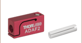
Cannulae and patch cables with different ferrule materials can be mixed and matched without introducing significant additional signal losses. However, fiber core sizes, numerical apertures (NA), and ferrule diameters should match for proper connection and maximum signal strength. Ø1.25 mm ferrules can be connected using an ADAL1 mating sleeve or ADAL3 interconnect, while Ø2.5 mm ferrules use an ADAF1 mating sleeve or ADAF2 interconnect.
Custom Rotary Joint Cables
The fiber leads of these cables are permanently attached to the rotary joint for higher performance and provide a one piece, integrated fiber optic solution. For compatibility with a wide range of cannulae, light sources, and experimental setups, we can produce custom rotary joint cables using fibers with different core sizes and NAs. We can also produce cables with different connectors or any length of fiber on each end of the joint. For best performance, the fiber core size should be 200 µm or greater. We also offer Standard Rotary Joint Cables, with SMA or FC/PC connectors on each end. Contact Tech Support to order a custom rotary joint cable.
Optogenetics Product Family for In Vivo Applications
Thorlabs offers a wide variety of products designed to support in vivo optogenetics applications. Please visit the OG Selection Guide tab above to see a full listing of available products for different applications.
| Specifications | |||||||||||
|---|---|---|---|---|---|---|---|---|---|---|---|
| Item # | RJPFL2 | RJPSL2 | RJPFF2 | RJPSF2 | RJAFF2 | RJASF2 | RJPFL4 | RJPSL4 | RJPFF4 | RJPSF4 | |
| Ferrule End | Ø1.25 mm | Ø2.5 mm | Ø1.25 mm | Ø2.5 mm | |||||||
| Light Source Connector | FC/PC | SMA | FC/PC | SMA | FC/PC | SMA | FC/PC | SMA | FC/PC | SMA | |
| Fiber Type | FT200EMT | FT400EMT | |||||||||
| Fiber Core Size | Ø200 µm | Ø400 µm | |||||||||
| Fiber NA | 0.39 | ||||||||||
| Wavelength Range | 400 - 2200 nm (Click for Plot) | ||||||||||
| Length | 3 m (1 m on Specimen Side of Rotary Joint, 2 m on Light Source Side) | ||||||||||
| Fiber Jacket | Light Source Side | Ø2 mm, Orange PVC (FT020) | |||||||||
| Specimen Side | Ø1/16" (Ø1.6 mm) Black Heat Shrink | Ø2.3 mm (FT023SS) Furcation Tubing |
Ø1/16" (Ø1.6 mm) Black Heat Shrink | ||||||||
| Rotary Joint Specifications | |||||||||||
| Total Transmission Through Rotary Jointa | >63% (Insertion Loss <2.0 dB) | ||||||||||
| Variation in Transmission During Rotationa | ±8% (±0.4 dB) | ||||||||||
| Start-Up Torque | <0.01 N•m <150 µN•m (Typical) |
||||||||||
| Operating Temperature | <50 °C | ||||||||||
Fiber Specs
| Item # Suffix | Fiber Type | NA | Core / Cladding |
Core Diameter |
Cladding Diameter |
Coating Diameter |
Max Core Offset |
Bend Radius (Short Term / Long Term) |
|---|---|---|---|---|---|---|---|---|
| -L2 or -F2 | FT200EMT | 0.39 ± 0.02 | Pure Silica / TECS Hard Cladding | 200 ± 5 μm | 225 ± 5 μm | 500 ± 30 μm | 5 µm | 21 mm / 42 mm |
| -L4 or -F4 | FT400EMT | 400 ± 8 μm | 425 ± 10 μm | 730 ± 30 μm | 7 µm | 43 mm / 86 mm |
Rotary Joint Mounting Options
The rotary joint included in our articulated patch cables features external SM05 (0.535"-40) threading on the non-rotating section. This allows the rotary joint to be mounted into our standard optomechanical hardware and positioned above a specimen enclosure. A selection of example mounts are shown below and to the right, and each can be configured based on enclosure size. Additionally, rotary joints can be custom mounted in enclosure walls or ceilings (bottom right) using either our SM05 tap or by gluing the rotary joint into a ~Ø1/2" hole.
Click to Enlarge
The rotary joint is engraved with the part number and has external SM05 (0.535"-40) threading for convenient mounting.
Clamp to 1/2" Post
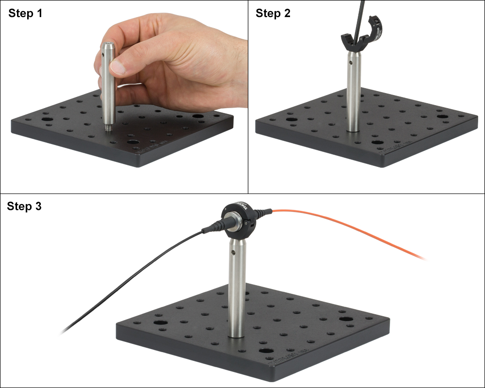
This mounting option utilizes our C059TC Tube Clamp to easily secure the stationary end of our rotary joints. This clamp allows you to swap between cables without disassembling your setup.
To build this mount, first screw a TR3 post to the breadboard using the SS25S050 setscrew. Next, mount the C059TC to the end of the post with an SH8S025 cap screw. Then, simply place the rotary joint and clamp down on the thicker, static section, letting the rotating section move freely. Tighten the captive locking screw on the clamp using a 5/64" hex key.
High Mass Ø1.5" Post Mount
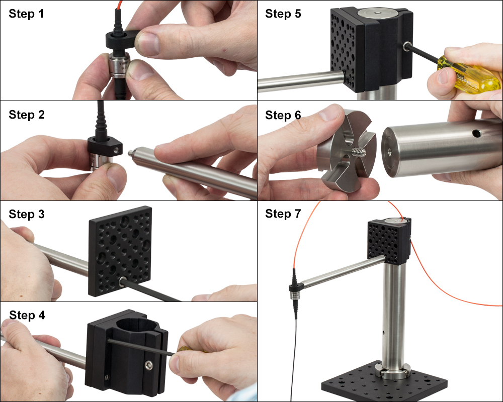
This mounting option uses our Ø1.5" optical post to create a highly stable rotary joint mount. The high mass post and breadboard keep the rotary joint firmly in place. The P10 Ø1.5" post and TR8 Ø1/2" post may be substituted with other posts of different lengths, plus the C1511 post clamp may be positioned anywhere along the Ø1.5" post to accommodate different specimen enclosure sizes.
To build this mount, first mount the rotary joint in the LMR05 mount: Unthread the retaining ring inside the LMR05 mount. Then, pull the orange cable through the LMR05, and thread the rotary joint into the mount. Next, mount the LMR05 to the tapered end of the TR8 post using the included setscrew. Remove the front plate of the C1511 and mount the TR8 to one of the front plate's 1/4" counterbores using one of the SH25S038 cap screws, making sure the rotary joint is oriented correctly while the screw is tightened. Reattach the mounting plate to the C1511 post clamp, and slide it onto the P10 post, tightening the screw to lock its position. Screw the PB2 base onto the end of the P10 post using a SS25S050 setscrew and attach it to the breadboard using four SH25S038 cap screws.
Adjustable Ø1/2" Post Mount
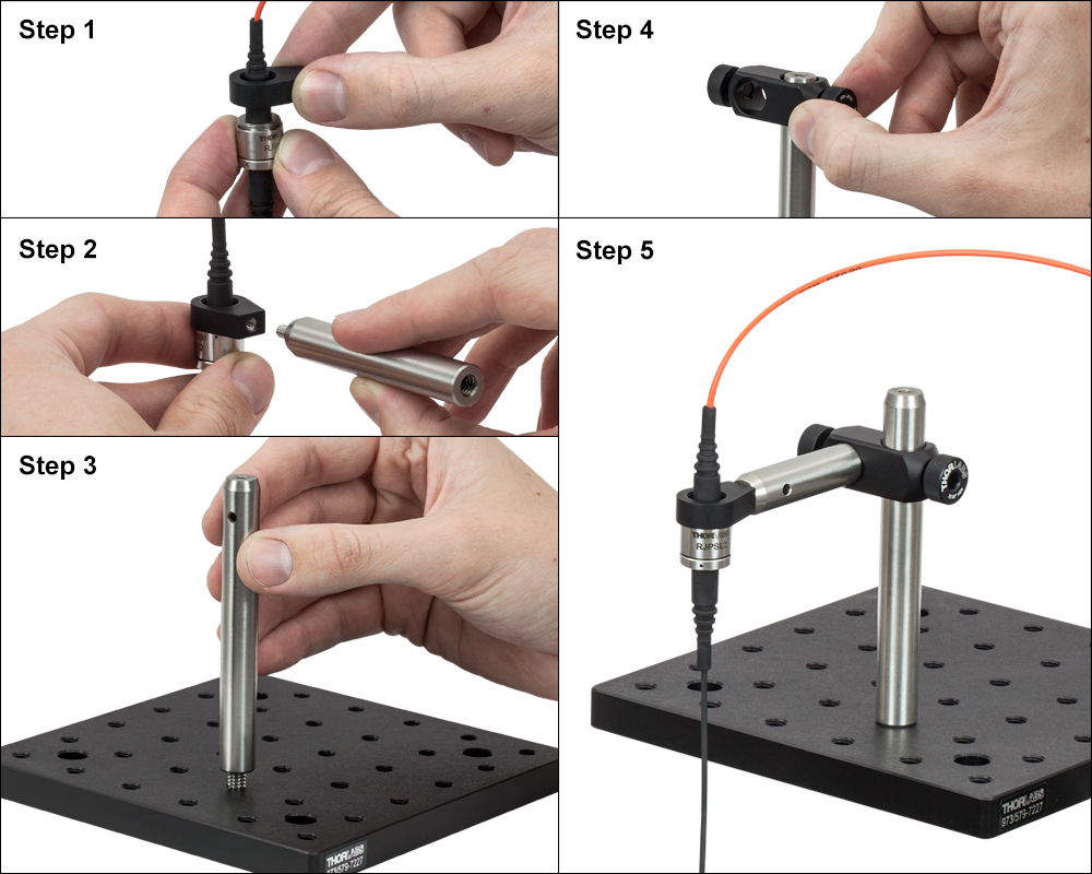
This mounting option uses our Ø1/2" optical posts to create a quickly adjustable rotary joint mount. The breadboard base keeps the rotary joint firmly in place, while the RA90 post clamp allows the position of the rotary joint to be easily adjusted. The TR3 and TR4 Ø1/2" posts may be substituted with other posts of different lengths to accommodate different specimen enclosure sizes.
To build this mount, first mount the rotary joint in the LMR05 mount: Unthread the retaining ring inside the LMR05 mount. Then, pull the orange cable through the LMR05, and thread the rotary joint into the mount. Next, mount the LMR05 to the tapered end of the TR3 post using the included setscrew. Attach the TR4 post to the breadboard using the SS25S050 setscrew, and slide the RA90 onto the top of the post. Slide the TR3 into the other hole of the RA90, and tighten the thumbscrews to lock the position of the rotary joint.
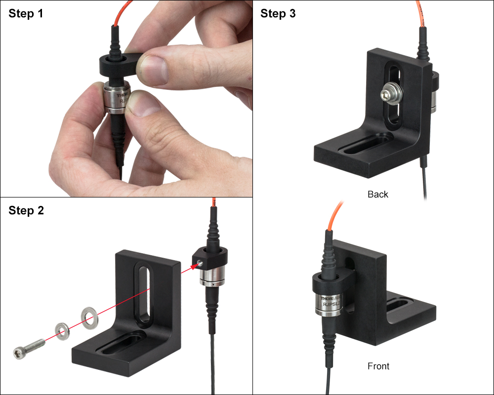
Angle Bracket Mount
This mounting option uses our AB90 angle bracket for a low-profile, low-cost setup. The angle bracket's 1/4" counterbored slot in the base can be used to attach it to any wood, plastic, or metal surface using the appropriate screws.
To build this mount, first mount the rotary joint in the LMR05 mount: Unthread the retaining ring inside the LMR05 mount. Then, pull the orange cable through the LMR05, and screw the rotary joint into the mount. To mount the LMR05 mount to one of the counterbored slots in the AB90, stack the SD1 ring and W25S050 washer onto the SS8S075 screw and thread them through the AB90's counterbored slot (click photo for details).
Custom Enclosure Mount
The rotary joint can be mounted in an acrylic sheet (pictured), wood, plastic, or metal enclosure walls and ceilings that have an SM05-threaded (0.535"-40) hole.
Custom holes can be tapped using our 83373 SM05 tap. First, drill or mill out a Ø0.508" hole where the rotary joint is to be mounted. Next, mount the tap in a drill press and manually turn it into the hole to cut threads into the material. To mount the rotary joint, insert the rotary joint's threads into the enclosure wall from the inside.
Alternatively, a ~Ø1/2" hole can be drilled into the enclosure wall, and the rotary joint can be glued into place. Insert the threaded section into the hole from the inside of the enclosure, and do not allow glue to contact the rotating mechanism. We recommend using our G14250 5-minute epoxy.
| Posted Comments: | |
Marc mieuset
(posted 2020-09-17 18:42:04.357) Hi, The RJPFF2, works with Monomode ? SM28 or else. Thanks.
Marc YLohia
(posted 2020-09-18 09:23:12.0) Hello Marc, thank you for contacting Thorlabs. Yes, the RJPFF2 can be used on the output end of the SMF28 fibers (since the core size and the NA of the FT200EMT fiber used in the RJPFF2 are much larger than that of the SMF28 type fibers). However, please note that the insertion loss will be extremely high if you plug in the SMF28 fiber on the output of the RJPFF2. simon.mcmullan
(posted 2017-06-26 12:10:12.513) Hi
We've suffered a fibre break near to our rotary; is there any way we can fix this? In particular, information on how to remove the ceramic ferrule from a rotary cable would be very useful.
Kind regards
Simon tfrisch
(posted 2017-06-27 03:19:22.0) Hello, thank you for contacting Thorlabs. Unfortunately, the ferrule is glued in place and cannot be removed for repair. I will reach out to you directly. kellyz
(posted 2013-09-17 19:41:20.527) Greetings!
I would love to be able to purchase JUST the rotary joint from you.
I usually work with 300um fiber, and the fiber that connects the rotary joint to the animal needs to be about 0.5m long.
I usually order rotary joints from Doric, but if you guys are able to sell them separately, I'd certainly switch.
Thanks!
Kelly jlow
(posted 2013-09-18 11:41:00.0) Response from Jeremy at Thorlabs: The fiber ends are permanently attached to the rotary joint for better performance and to provide a one piece, integrated fiber optic solution. However, we can quote made-to-order rotary joint cables with any length of fiber on each end of the joint, as well as using fibers with different core sizes and NAs. For best performance, the fiber core size should be 200 µm or greater. I will contact you directly to discuss about this. |
| Quick Links | |||
|---|---|---|---|
| Single-Site Stimulation | |||
| One Light Source to One Cannula Implant | |||
| Multilateral Stimulation | |||
| One Light Source to Two Cannula Implants Using Rotary Joint Splitter | |||
| One or Two Light Sources to Two Cannula Implants | |||
| One Light Source to Seven Cannula Implants | |||
| Two Light Sources into One Dual-Core Cannula Implant | |||
| Illumination | |||
| Fiber-Coupled LEDs and Drivers | |||
Optogenetics Selection Guide
Thorlabs offers a wide range of optogenetics components; the compatibility of these products in select standard configurations is discussed in detail here. Please contact Technical Support for assistance with items outside the scope of this guide, including custom fiber components for optogenetics.
Single-Site Stimulation
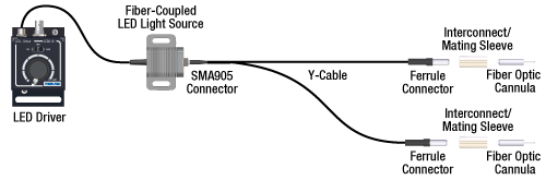
One Light Source to One Cannula Implant
The most straightforward method for in vivo light stimulation of a specimen is to use a single fiber optic with a single LED light source. The single wavelength LED is powered by an LED driver, and then the illumination output is fiber-coupled into a patch cable, which connects to the implanted cannula. See the graphics and expandable compatibility tables below for the necessary patch cables and cannulae to create this setup. To choose the appropriate LED and driver, see below or the full web presentation.
Click on Each Component for More Information
Click to See Ø1.25 mm (LC) Ferrule Compatible Patch Cables, Cannulae, and Interconnects
Click to See Ø2.5 mm (FC) Ferrule Compatible Patch Cables, Cannulae, and Interconnects
Multilateral Stimulation
The ability to accurately and simultaneously direct light to multiple locations within a specimen is desired for many types of optogenetics experiments. For example, bilateral stimulation techniques typically target neurons in two spatially separated regions in order to induce a desired behavior. In more complex experiments involving the simultaneous inhibition and stimulation of neurons, delivering light of two different monochromatic wavelengths within close proximity enables the user to perform these experiments without implanting multiple cannulae, which can increase stress on the specimen.
Multilateral stimulation can be achieved with several different configurations depending on the application requirements. The sections below illustrate examples of different configurations using Thorlabs' optogenetics products.
Option 1: One Light Source to Two Cannula Implants Using Rotary Joint Splitter
Thorlabs' RJ2 1x2 Rotary Joint Splitter is designed for optogenetics applications and is used to split light from a single input evenly between two outputs. The rotary joint interface allows connected patch cables to freely rotate, reducing the risk of fiber damage caused by a moving specimen. See the graphic and compatibility table below for the necessary cables and cannulae to create this setup. For LEDs and drivers, see below or the full web presentation.
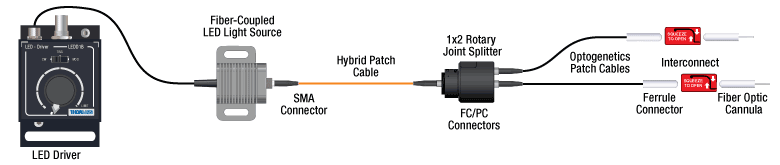
Click to See Ø1.25 mm (LC) Ferrule Components Recommended for Use with RJ2 Rotary Joint Splitter
Click to See Ø2.5 mm (FC) Ferrule Components Recommended for Use with RJ2 Rotary Joint Splitter
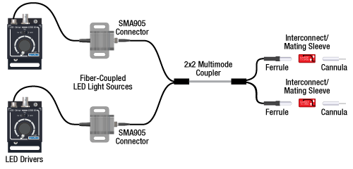
Option 2: One or Two Light Sources to Two Cannula Implants
If the intent is for one LED source to connect to two cannulae for simultaneous light modulation, then a bifurcated fiber bundle can be used to split the light from the LED into each respective cannula. For dual wavelength stimulation (mixing two wavelengths in a single cannula) or a more controlled split ratio between cannula, one can use a multimode coupler to connect one or two LEDs to the cannulae. If one cable end is left unused, the spare coupler cable end may be terminated by a light trap. See the graphic and compatibility table below for the necessary cables and cannulae to create this setup. For LEDs and drivers, see below or the full web presentation.
Click on Each Component Below for More Information
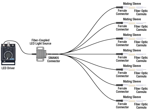
Option 3: One Light Sources to Seven Cannula Implants
If the intent is for one LED source to connect to seven cannulae for simultaneous light modulation, then a 1-to-7 fiber bundle can be used to split the light from the LED into each respective cannula. See the graphic and compatibility table below for the necessary cables and cannulae to create this setup. For LEDs and drivers, see below or the full web presentation.
Click on Each Component Below for More Information
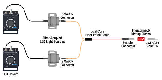
Two Light Sources into One Dual-Core Cannula Implant
For bilateral stimulation applications where the two cannulas need to be placed in close proximity (within ~1 mm), Thorlabs offers dual-core patch cables and cannulae that are designed for this specific application. Each core is driven by a separate light source, enabling users to stimulate and/or supress nerve cells in the same region of the specimen. See the graphic and compatibility table below for the necessary cables and cannulae to create this setup. For LEDs and drivers, see below or the full web presentation.
Click on Each Component for More Information
| Part Selection Table (Click Links for Item Description Popup) | |||||||||
|---|---|---|---|---|---|---|---|---|---|
| Common Fiber Properties | |||||||||
| Core Diameter | 200 µm | ||||||||
| Wavelength Range | 400 - 2200 nm | ||||||||
| NA | 0.39 | ||||||||
| Fiber Type | FT200EMT | ||||||||
| Ferrule Stylea | FC (Ø2.5 mm) | ||||||||
| Dual-Core Patch Cable | FC/PC Input | BFY32FL1 | |||||||
| SMA905 Input | BFY32SL1 | ||||||||
| Compatible Mating Sleeve/Interconnect | ADAF1 ADAF2 ADAF4-5 |
||||||||
| Dual-Core Fiber Optic Cannulaec | Stainless Steel | CFM32L10 CFM32L20 |
|||||||
| LED Item # | Wavelengtha | Typical Opsin | Output Powerb | Color |
|---|---|---|---|---|
| M385F1c | 385 nm | EBFP, moxBFP | 10.7 mW | UV |
| M405F1c | 405 nm | mmilCFP, hcriGFP | 3.7 mW | UV |
| M430F1 | 430 nm | ChR2 | 7.5 mW | Violet |
| M455F3 | 455 nm | ChIEF, bPAC | 24.5 mW | Royal Blue |
| M505F3 | 505 nm | ChRGR, Opto-α1AR, Opto-β2AR | 11.7 mW | Cyan |
| M530F2 | 530 nm | C1V1, VChR1 | 9.6 mW | Green |
| M565F3 | 565 nm | Arch, VChR1-SFO | 13.5 mW | Lime |
| M595F2 | 595 nm | ChR2-SFO, eNpHR3.0 | 11.5 mW | Amber |
| M625F2 | 625 nm | ReChR | 17.5 mW | Red |
Illumination
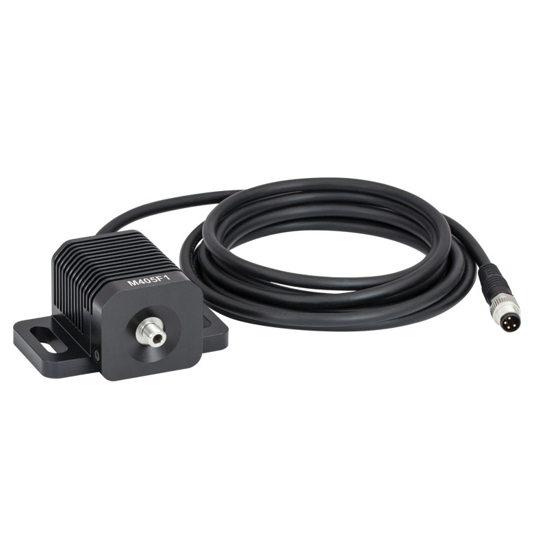
Click to Enlarge
M405F1
Fiber-Coupled LEDs and Drivers
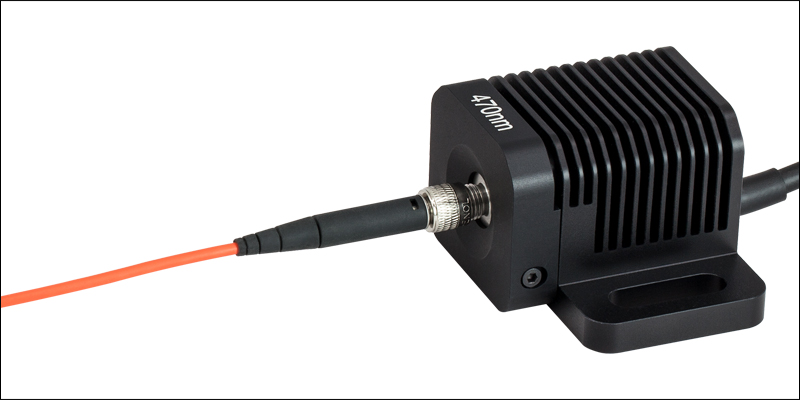
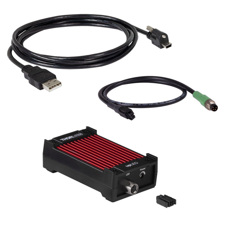
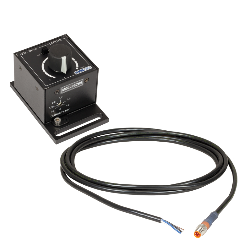
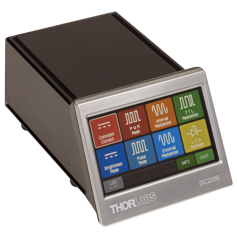
Our fiber-coupled LEDs are ideal light sources for optogenetics applications. They feature a variety of wavelength choices and a convenient interconnection to optogenetics patch cables. Thorlabs offers fiber-coupled LEDs with nominal wavelengths ranging from 280 nm to 1050 nm. See the table to the right for the LEDs with the most popular wavelengths for optogenetics. A table of compatible LED drivers can be viewed by clicking below.


 Zoom
Zoom- Heat-Shrink Tubing (Ø1/16") Minimizes Pressure on the Specimen
- Patch Cable Length: 3 m
- Compatible Cannulae: CFMLC12 Ceramic Cannulae and CFML12 Stainless Steel Cannulae
| Fiber Type |
Wavelength Range (Click for Plot) |
Core Diameter | NA | Transmission through Rotary Jointa |
Cable Mass | Ferrule Diameter |
Ferrule Material |
|---|---|---|---|---|---|---|---|
| FT200EMT | 400 - 2200 nm | 200 µm ± 5 µm | 0.39 | >63% (<2.0 dB); ±8% (±0.4 dB) Variation During Rotation |
365 g | 1.25 mm | Ceramic (Zirconia) |

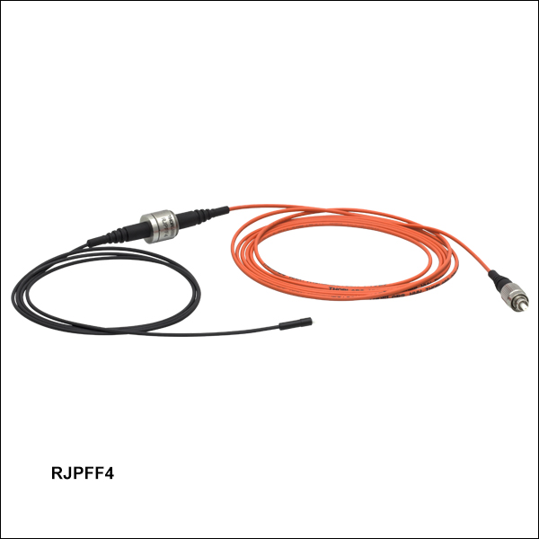
 Zoom
Zoom- Heat-Shrink Tubing (Ø1/16") Minimizes Pressure on the Specimen
- Patch Cable Length: 3 m
- Compatible Cannulae: CFMC12 Ceramic Cannulae and CFM12 Stainless Steel Cannulae
| Fiber Type |
Wavelength Range (Click for Plot) |
Core Diameter | NA | Transmission through Rotary Jointa |
Cable Mass | Ferrule Diameter |
Ferrule Material |
|---|---|---|---|---|---|---|---|
| FT200EMT | 400 - 2200 nm | 200 µm ± 5 µm | 0.39 | >63% (<2.0 dB); ±8% (±0.4 dB) Variation During Rotation |
342 g | 2.5 mm | Ceramic (Zirconia) |

 Zoom
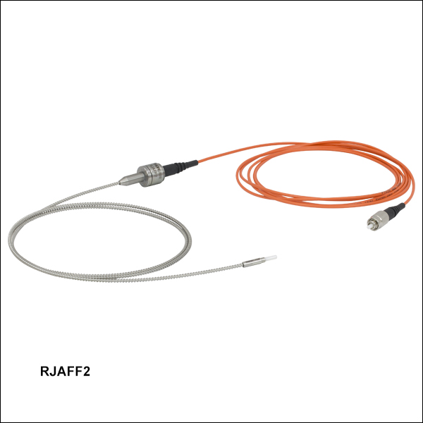
Zoom- Stainless Steel Tubing Ø2.3 mm Provides Maximum Protection from the Specimen
- Patch Cable Length: 3 m
- Compatible Cannulae: CFMC12 Ceramic Cannulae and CFM12 Stainless Steel Cannulae
| Fiber Type |
Wavelength Range (Click for Plot) |
Core Diameter | NA | Transmission through Rotary Jointa |
Cable Mass | Ferrule Diameter |
Ferrule Material |
|---|---|---|---|---|---|---|---|
| FT200EMT | 400 - 2200 nm | 200 µm ± 5 µm | 0.39 | >63% (<2.0 dB); ±8% (±0.4 dB) Variation During Rotation |
365 g | 2.5 mm | Ceramic (Zirconia) |

 Zoom
Zoom- Heat-Shrink Tubing (Ø1/16") Minimizes the Pressure on the Specimen
- Patch Cable Length: 3 m
- Compatible Cannulae: CFMLC14 Ceramic Cannulae and CFML14 Stainless Steel Cannulae
| Fiber Type |
Wavelength Range (Click for Plot) |
Core Diameter | NA | Transmission through Rotary Jointa |
Cable Mass | Ferrule Diameter |
Ferrule Material |
|---|---|---|---|---|---|---|---|
| FT400EMT | 400 - 2200 nm | 400 µm ± 8 µm | 0.39 | >63% (<2.0 dB); ±8% (±0.4 dB) Variation During Rotation |
342 g | 1.25 mm | Ceramic (Zirconia) |

 Zoom
Zoom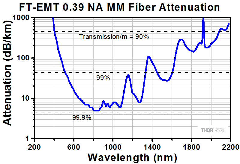
- Heat-Shrink Tubing (Ø1/16") Minimizes the Pressure on the Specimen
- Patch Cable Length: 3 m
- Compatible Cannulae: CFMC14 Ceramic Cannulae and CFM14 Stainless Steel Cannulae
| Fiber Type |
Wavelength Range (Click for Plot) |
Core Diameter | NA | Transmission through Rotary Jointa |
Cable Mass | Ferrule Diameter |
Ferrule Material |
|---|---|---|---|---|---|---|---|
| FT400EMT | 400 - 2200 nm | 400 µm ± 8 µm | 0.39 | >63% (<2.0 dB); ±8% (±0.4 dB) Variation During Rotation |
342 g | 2.5 mm | Ceramic (Zirconia) |