 Products Home / Lasers / Coherent Sources / Femtosecond Lasers / Menlo Femtosecond Fiber Lasers / Asynchronous Optical Sampling (ASOPS) Technique
Asynchronous Optical Sampling (ASOPS) Technique
- Solutions for Pump-Probe and Two-Color Pump-Probe Spectroscopy
- High-Speed Scanning
- No Mechanical
Adjustment Necessary
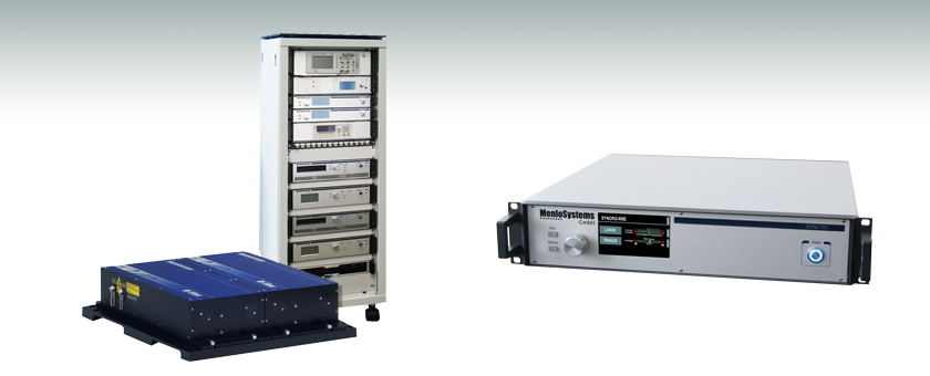
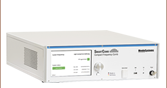
ASOPS-TWIN
Asynchronous Optical Sampling System
RRE-SYNCRO
Repetition Rate Stabilization


Please Wait
 Jason Reeves Menlo Systems |
Feedback? Questions? Need a Quote? Please note that these ASOPS and Repetition Rate Stabilization Systems are available directly from Menlo Systems, Inc. within the United States and from Menlo Systems GmbH outside the United States. |
| United States Phone: +1-303-635-6406 Email: ussales@menlosystems.com |
|
| Outside United States Phone: +49-89-189166-0 Email: sales@menlosystems.com |
|
Applications
ASOPS-TWIN and ASOPS-DUAL-COLOR- Pump-Probe Spectroscopy
- FTIR Spectroscopy
- Time-Domain THz Spectroscopy
- Material Characterization
- Repetition Rate Synchronization
- Precision Timing
Optional Packages
VARIO User-Defined Repetition Rate
Factory-Set Value Selectable in the 50 - 250 MHz Range
MULTIBRANCH Additional Seed Ports
Seeding of Multiple Amplifiers with Optional Subsequent Frequency Conversion to Cover Multiple Wavelengths
ASOPS-TWIN and ASOPS-DUAL-COLOR
Features
- Measurements in a 4 ns or 10 ns Time Window
- Sub-150 fs Pulses
- Fiber-Coupled or Free-Space Design
- ASOPS Control Software
- See Specs Tab for Details
In time-resolved measurements, an ultrafast pulse triggers a reaction, and a second pulse takes a snapshot of the induced change. By shifting the arrival time of the probe pulse with respect to the pump pulse, the stimulated process can be followed in time.
The Asynchronous Optical Sampling (ASOPS) technique allows for high-speed scanning over a few nanoseconds of time delay without a mechanical delay line. The ultrafast lasers delivering the pump and probe pulses are locked together at a tunable repetition rate difference. The lasers can also be locked to the same repetition rate value, and by shifting the relative phase between the laser pulses, the system will allow measurements in a reduced time window of several hundred picoseconds. Switching between the two modes can be done at the touch of a button.
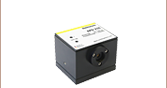
RRE-SYNCRO
Features
- Synchronization to Fixed or Tunable Repetition Rate
- Relative Timing Jitter <200 fs (RMS) (0.1 Hz - 500 kHz)
- Plug-and-Play Use
- Modular Design
- Fully Customizable
- Two-Stage Locking Scheme Possible (Fundamental/Harmonic)
The RRE-SYNCRO, included with the ASOPS-TWIN and ASOPS-DUAL-COLOR, provides state-of-the-art phase lock electronics used to synchronize pulsed laser sources with high accuracy. The main application is the synchronization of a pulsed laser to a radio frequency reference, derived from a radio frequency clock or an optical reference clock. An embedded microcontroller for the stepper motor and piezo control in the laser cavity ensures long-term stability. The complete, user-friendly system allows for plug-and-play use.
| Item # | ASOPS-TWIN | ASOPS-DUAL-COLOR | |
|---|---|---|---|
| Repetition Rate | 250 MHz | 100 MHz | |
| Repetition Rate Offset Tuning Range (Δf) | ±10 kHz, in Steps of 10-5 Hz | ||
| Time Measurement Window | 4 ns | 10 ns | |
| Scan Duration (1/Δf)a | 0.1 ms @ 10 kHz Offset, 1 s @ 1 Hz Offset |
||
| Data Point Incrementb | 160 fs @ 10 kHz, 0.016 fs @ 1 Hz |
1 ps @ 10 kHz, 0.1 fs @ 1 Hz |
|
| Relative Timing Jitter (RMS) (0.1 Hz - 500 kHz) | <150 fs | ||
| Laser Head Specifications | |||
| Wavelength | 1560 nm | 1560 nm | 780 nm |
| Average Output Power | >75 mW (From Each Laser) | >100 mW | |
| Output Port | Fiber Coupled, FC/APC | Free Space | |
| Pulse Length | <150 fsc | <90 fs | <120 fs |
| Piezo Tuning Range | >625 Hz | >100 Hz | |
| Piezo Bandwidth | >30 kHz | >30 kHz | |
| Stepper Motor Tuning Range | >2 MHz | >330 kHz | |
| Trigger Signal | TTL Level at Offset Frequency, <10 ns Rise Time |
||
| Environmental Specifications | |||
| Operating Voltage | 110/115/230 VAC | ||
| Frequency | 50 to 60 Hz | ||
| Cooling Requirements | No Water Cooling Required | ||
| Operating Temperature | 22 ± 5 °C | ||
| Optical Unit Dimensions / Weight | (16.3" x 15.7" x 4.3" / 77 lbs) |
(19.7" x 21.1" x 4.3" / 77 lbs) |
|
| Control Electronics Dimensions / Weight | Mounted in 19" Rack Cabinet 800 mm x 600 mm x 1800 mm / 75 kg (31.5" x 23.6" x 70.9" / 165 lbs) |
||
| Item # | RRE-SYNCRO |
|---|---|
| Relative Timing Jitter (RMS) | <200 fs (0.1 Hz - 500 kHz)a |
| External Reference Input | 10 MHzb, Signal Level +5 dBm to +10 dBm |
| Stepper Motor Signal Output | Stepper Motor Control, Sub-D, 9 Pin |
| Piezo Signal Output | Piezo Control 0 - 150 V, BNO |
| Error Signal Output | Error Signal for Monitoring, BNC |
| Environmental Specifications | |
| Operating Voltage | 110/220 V |
| Storage Temperature | 0 to 40 °C |
| Dimensions / Weight | 449 mm x 148 mm x 317 mm / 7 kg (17.7" x 5.8" x 12.5" / 15.4 lbs) |
| Remote Control | PC Connection via |
Pulsed Laser Emission: Power and Energy Calculations

Determining whether emission from a pulsed laser is compatible with a device or application can require referencing parameters that are not supplied by the laser's manufacturer. When this is the case, the necessary parameters can typically be calculated from the available information. Calculating peak pulse power, average power, pulse energy, and related parameters can be necessary to achieve desired outcomes including:
- Protecting biological samples from harm.
- Measuring the pulsed laser emission without damaging photodetectors and other sensors.
- Exciting fluorescence and non-linear effects in materials.
Pulsed laser radiation parameters are illustrated in Figure 170A and described in Table 170B. For quick reference, a list of equations is provided below. The document available for download provides this information, as well as an introduction to pulsed laser emission, an overview of relationships among the different parameters, and guidance for applying the calculations.
|
Equations: |
||||
 |
and |  |
||
 |
||||
 |
||||
 |
||||
Peak power and average power calculated from each other: |
||||
 |
and |  |
||
| Peak power calculated from average power and duty cycle*: | ||||
 |
*Duty cycle ( ) is the fraction of time during which there is laser pulse emission. ) is the fraction of time during which there is laser pulse emission. |
|||
Click to Enlarge
Figure 170A Parameters used to describe pulsed laser emission are indicated in this plot and described in Table 170B. Pulse energy (E) is the shaded area under the pulse curve. Pulse energy is, equivalently, the area of the diagonally hashed region.
| Table 170B Pulse Parameters | |||||
|---|---|---|---|---|---|
| Parameter | Symbol | Units | Description | ||
| Pulse Energy | E | Joules [J] | A measure of one pulse's total emission, which is the only light emitted by the laser over the entire period. The pulse energy equals the shaded area, which is equivalent to the area covered by diagonal hash marks. | ||
| Period | Δt | Seconds [s] | The amount of time between the start of one pulse and the start of the next. | ||
| Average Power | Pavg | Watts [W] | The height on the optical power axis, if the energy emitted by the pulse were uniformly spread over the entire period. | ||
| Instantaneous Power | P | Watts [W] | The optical power at a single, specific point in time. | ||
| Peak Power | Ppeak | Watts [W] | The maximum instantaneous optical power output by the laser. | ||
| Pulse Width |  |
Seconds [s] | A measure of the time between the beginning and end of the pulse, typically based on the full width half maximum (FWHM) of the pulse shape. Also called pulse duration. | ||
| Repetition Rate | frep | Hertz [Hz] | The frequency with which pulses are emitted. Equal to the reciprocal of the period. | ||
Example Calculation:
Is it safe to use a detector with a specified maximum peak optical input power of 75 mW to measure the following pulsed laser emission?
- Average Power: 1 mW
- Repetition Rate: 85 MHz
- Pulse Width: 10 fs
The energy per pulse:

seems low, but the peak pulse power is:

It is not safe to use the detector to measure this pulsed laser emission, since the peak power of the pulses is >5 orders of magnitude higher than the detector's maximum peak optical input power.
| Posted Comments: | |
| No Comments Posted |