 Products Home
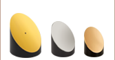
Reflective Beam Expanders: 2X, 4X, and 6X

- Expand or Reduce Polychromatic Beams
- Protected Silver Mirrors for 450 nm to 20 µm
- 2X, 4X, and 6X Magnifications
- Compatible with Cage Systems and Lens Tubes
BE06R
6X Magnification
BE02R
2X Magnification
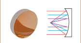
Input Beam is Angled
Relative to Output Beam


Please Wait
Click to Enlarge
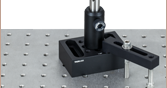
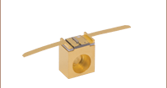
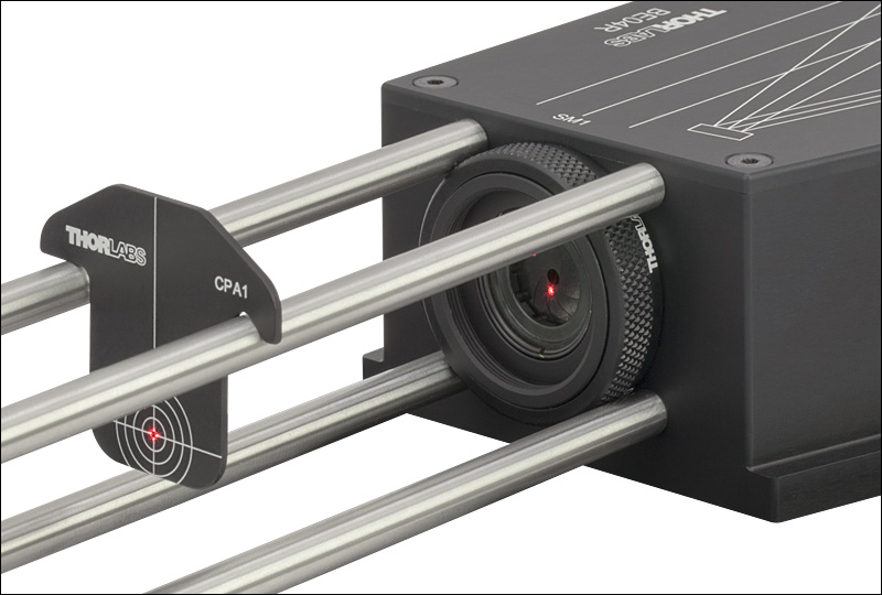
Figure 1.1 Alignment into BE04R Beam Expander using CPA1 Alignment Plate, SM1D12D Ring-Activated Iris, and 30 mm Cage Rods
Features
- Enlarge or Reduce the Diameter of a Collimated Beam by a Fixed Ratio
- 2X, 4X, and 6X Options
- Chromatic Compensation Provided by Spherical Mirrors
- High Transmission from 450 nm to 20 μm
- Max Input Beam Diameter (1/e2) of 3 mm for Diffraction-Limited Performance
Thorlabs' Reflective Beam Expanders use a pair of prealigned protected-silver-coated spherical mirrors to provide 2X, 4X, or 6X beam expansion or reduction. Unlike our transmissive beam expanders, they exhibit virtually zero chromatic aberration, making them especially suitable for broadband sources. The protected silver mirrors provide high reflectance over a broad spectral range (Ravg > 97% from 450 nm - 2 µm and Ravg > 95% from 2 µm - 20 µm), minimize the phase delays and absorption losses introduced by transmissive optics, and offer a low wavefront error of λ/10 (see the Specs tab for details). One particularly useful application of a reflective beam expander is to reduce the diameter of a polychromatic beam and then couple the light into multimode fiber using a reflective collimator.
| Table 1.2 Cage System and Lens Tube Compatibility | ||||
|---|---|---|---|---|
| Item # | BE02R(/M) | BE04R(/M) | BE06R(/M) | |
| Magnification | 2X | 4X | 6X | |
| Input Port | Cage System | 16 mm | 16 mm | 30 mm |
| Lens Tube | SM05 | SM05 | SM05 | |
| Output Port | Cage System | 16 mm | 30 mm | 30 mm |
| Lens Tube | SM05 | SM1 | SM30 | |
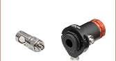
To simplify alignment, the input and output ports of each beam expander feature SM05 (0.535"-40), SM1 (1.035"-40), or SM30 (M30.5 x 0.5) threading for compatibility with our SM-threaded lens tubes, as well as four 4-40 tapped holes for compatibility with our 16 mm and 30 mm cage systems. The SM threading and cage compatibility of each beam expander is detailed in Table 1.2.
To secure the reflective beam expanders to an optical table, use two CL2(/M), CL3(/M), or CL6 Table Clamps to hold the lip of the housing against the table's surface. The BE04R and BE06R beam expanders also feature through holes that accept 1/4"-20 and M6 cap screws, which can be used to mount the beam expander to the table or elevate the beam expander in combination with Ø1" Pedestal Pillar Posts. If vertical mounting is desired, each reflective beam expander includes a mounting plate with four 8-32 (M4) tapped holes at 1" (25 mm) spacings, suitable for connecting the housing to Ø1/2" Posts.
Thorlabs also manufactures many other types of beam expanders, including Galilean beam expanders with variable or fixed zoom ratios. Both sliding and rotating adjustment mechanisms are available. For more information, please visit the Beam Expanders tab.
| Item # | BE02R(/M) | BE04R(/M) | BE06R(/M) | |
|---|---|---|---|---|
| Magnification | 2X | 4X | 6X | |
| Reflectancea (Avg.) | 450 nm - 2 µm: >97% 2 - 20 µm: >95% |
|||
| Max Input Beam Diameterb (1/e2) | 3 mm | |||
| Wavefront Error (RMS) | λ/10 for a Ø1.5 mm Input Beam |
λ/10 for a Ø1.0 mm Input Beam |
λ/10 for a Ø0.5 mm Input Beam |
|
| Angle Between Input and Output Beams |
11° | 14° | 16.4° | |
| Clear Input Aperture | Ø6 mm | |||
| Surface Quality | 40-20 Scratch-Dig | |||
| Damage Threshold | Pulsed | 3 J/cm2 (1064 nm, 10 ns, 10 Hz, Ø1.000 mm) | ||
| CW | 500 W/cm (1.07 µm, Ø0.974 mm) 1500 W/cm (10.6 µm, Ø0.339 mm) |
|||
| Mirror Substrate | N-BK7 | |||
 Click to Enlarge
Excel Spreadsheet with Raw Data for Protected Silver
Figure 2.1 This graph shows the reflectance per surface. The shaded region denotes the range over which we recommend using these beam expanders.
 Click to Enlarge
Excel Spreadsheet with Raw Data for BExxR(/M)
Figure 2.2 This graph shows the simulated peak-to-valley (P-V) reflected wavefront error in units of wavelength for the BE02R(/M), BE04R(/M), and BE06R(/M) reflective beam expanders.
| Table 3.1 Damage Threshold Specifications | |
|---|---|
| Mirror Coating Designation | Damage Threshold |
| -P01 (Pulsed) | 3 J/cm2 (1064 nm, 10 ns, 10 Hz, Ø1.000 mm) |
| -P01 (CWa) | 500 W/cm (1.07 µm, Ø0.974 mm) 1500 W/cm (10.6 µm, Ø0.339 mm) |
Damage Threshold Data for Thorlabs' Protected Silver Mirrors
The specifications in Table 3.1 are measured data for Thorlabs' Protected Silver Mirrors, which are used inside our Reflective Optical Beam Expanders. Damage threshold specifications are constant for a given coating type, regardless of the size of the mirror.
Laser Induced Damage Threshold Tutorial
The following is a general overview of how laser induced damage thresholds are measured and how the values may be utilized in determining the appropriateness of an optic for a given application. When choosing optics, it is important to understand the Laser Induced Damage Threshold (LIDT) of the optics being used. The LIDT for an optic greatly depends on the type of laser you are using. Continuous wave (CW) lasers typically cause damage from thermal effects (absorption either in the coating or in the substrate). Pulsed lasers, on the other hand, often strip electrons from the lattice structure of an optic before causing thermal damage. Note that the guideline presented here assumes room temperature operation and optics in new condition (i.e., within scratch-dig spec, surface free of contamination, etc.). Because dust or other particles on the surface of an optic can cause damage at lower thresholds, we recommend keeping surfaces clean and free of debris. For more information on cleaning optics, please see our Optics Cleaning tutorial.
Testing Method
Thorlabs' LIDT testing is done in compliance with ISO/DIS 11254 and ISO 21254 specifications.
First, a low-power/energy beam is directed to the optic under test. The optic is exposed in 10 locations to this laser beam for 30 seconds (CW) or for a number of pulses (pulse repetition frequency specified). After exposure, the optic is examined by a microscope (~100X magnification) for any visible damage. The number of locations that are damaged at a particular power/energy level is recorded. Next, the power/energy is either increased or decreased and the optic is exposed at 10 new locations. This process is repeated until damage is observed. The damage threshold is then assigned to be the highest power/energy that the optic can withstand without causing damage. A histogram such as that shown in Figure 37B represents the testing of one BB1-E02 mirror.
Figure 37A This photograph shows a protected aluminum-coated mirror after LIDT testing. In this particular test, it handled 0.43 J/cm2 (1064 nm, 10 ns pulse, 10 Hz, Ø1.000 mm) before damage.
Figure 37B Example Exposure Histogram used to Determine the LIDT of
| Table 37C Example Test Data | |||
|---|---|---|---|
| Fluence | # of Tested Locations | Locations with Damage | Locations Without Damage |
| 1.50 J/cm2 | 10 | 0 | 10 |
| 1.75 J/cm2 | 10 | 0 | 10 |
| 2.00 J/cm2 | 10 | 0 | 10 |
| 2.25 J/cm2 | 10 | 1 | 9 |
| 3.00 J/cm2 | 10 | 1 | 9 |
| 5.00 J/cm2 | 10 | 9 | 1 |
According to the test, the damage threshold of the mirror was 2.00 J/cm2 (532 nm, 10 ns pulse, 10 Hz, Ø0.803 mm). Please keep in mind that these tests are performed on clean optics, as dirt and contamination can significantly lower the damage threshold of a component. While the test results are only representative of one coating run, Thorlabs specifies damage threshold values that account for coating variances.
Continuous Wave and Long-Pulse Lasers
When an optic is damaged by a continuous wave (CW) laser, it is usually due to the melting of the surface as a result of absorbing the laser's energy or damage to the optical coating (antireflection) [1]. Pulsed lasers with pulse lengths longer than 1 µs can be treated as CW lasers for LIDT discussions.
When pulse lengths are between 1 ns and 1 µs, laser-induced damage can occur either because of absorption or a dielectric breakdown (therefore, a user must check both CW and pulsed LIDT). Absorption is either due to an intrinsic property of the optic or due to surface irregularities; thus LIDT values are only valid for optics meeting or exceeding the surface quality specifications given by a manufacturer. While many optics can handle high power CW lasers, cemented (e.g., achromatic doublets) or highly absorptive (e.g., ND filters) optics tend to have lower CW damage thresholds. These lower thresholds are due to absorption or scattering in the cement or metal coating.
Figure 37D LIDT in linear power density vs. pulse length and spot size. For long pulses to CW, linear power density becomes a constant with spot size. This graph was obtained from [1].
Figure 37E Intensity Distribution of Uniform and Gaussian Beam Profiles
Pulsed lasers with high pulse repetition frequencies (PRF) may behave similarly to CW beams. Unfortunately, this is highly dependent on factors such as absorption and thermal diffusivity, so there is no reliable method for determining when a high PRF laser will damage an optic due to thermal effects. For beams with a high PRF both the average and peak powers must be compared to the equivalent CW power. Additionally, for highly transparent materials, there is little to no drop in the LIDT with increasing PRF.
In order to use the specified CW damage threshold of an optic, it is necessary to know the following:
- Wavelength of your laser
- Beam diameter of your beam (1/e2)
- Approximate intensity profile of your beam (e.g., Gaussian)
- Linear power density of your beam (total power divided by 1/e2 beam diameter)
Thorlabs expresses LIDT for CW lasers as a linear power density measured in W/cm. In this regime, the LIDT given as a linear power density can be applied to any beam diameter; one does not need to compute an adjusted LIDT to adjust for changes in spot size, as demonstrated in Figure 37D. Average linear power density can be calculated using this equation.

This calculation assumes a uniform beam intensity profile. You must now consider hotspots in the beam or other non-uniform intensity profiles and roughly calculate a maximum power density. For reference, a Gaussian beam typically has a maximum power density that is twice that of the uniform beam (see Figure 37E).
Now compare the maximum power density to that which is specified as the LIDT for the optic. If the optic was tested at a wavelength other than your operating wavelength, the damage threshold must be scaled appropriately. A good rule of thumb is that the damage threshold has a linear relationship with wavelength such that as you move to shorter wavelengths, the damage threshold decreases (i.e., a LIDT of 10 W/cm at 1310 nm scales to 5 W/cm at 655 nm):

While this rule of thumb provides a general trend, it is not a quantitative analysis of LIDT vs wavelength. In CW applications, for instance, damage scales more strongly with absorption in the coating and substrate, which does not necessarily scale well with wavelength. While the above procedure provides a good rule of thumb for LIDT values, please contact Tech Support if your wavelength is different from the specified LIDT wavelength. If your power density is less than the adjusted LIDT of the optic, then the optic should work for your application.
Please note that we have a buffer built in between the specified damage thresholds online and the tests which we have done, which accommodates variation between batches. Upon request, we can provide individual test information and a testing certificate. The damage analysis will be carried out on a similar optic (customer's optic will not be damaged). Testing may result in additional costs or lead times. Contact Tech Support for more information.
Pulsed Lasers
As previously stated, pulsed lasers typically induce a different type of damage to the optic than CW lasers. Pulsed lasers often do not heat the optic enough to damage it; instead, pulsed lasers produce strong electric fields capable of inducing dielectric breakdown in the material. Unfortunately, it can be very difficult to compare the LIDT specification of an optic to your laser. There are multiple regimes in which a pulsed laser can damage an optic and this is based on the laser's pulse length. The highlighted columns in Table 37F outline the relevant pulse lengths for our specified LIDT values.
Pulses shorter than 10-9 s cannot be compared to our specified LIDT values with much reliability. In this ultra-short-pulse regime various mechanics, such as multiphoton-avalanche ionization, take over as the predominate damage mechanism [2]. In contrast, pulses between 10-7 s and 10-4 s may cause damage to an optic either because of dielectric breakdown or thermal effects. This means that both CW and pulsed damage thresholds must be compared to the laser beam to determine whether the optic is suitable for your application.
| Table 37F Laser Induced Damage Regimes | ||||
|---|---|---|---|---|
| Pulse Duration | t < 10-9 s | 10-9 < t < 10-7 s | 10-7 < t < 10-4 s | t > 10-4 s |
| Damage Mechanism | Avalanche Ionization | Dielectric Breakdown | Dielectric Breakdown or Thermal | Thermal |
| Relevant Damage Specification | No Comparison (See Above) | Pulsed | Pulsed and CW | CW |
When comparing an LIDT specified for a pulsed laser to your laser, it is essential to know the following:
Figure 37G LIDT in energy density vs. pulse length and spot size. For short pulses, energy density becomes a constant with spot size. This graph was obtained from [1].
- Wavelength of your laser
- Energy density of your beam (total energy divided by 1/e2 area)
- Pulse length of your laser
- Pulse repetition frequency (prf) of your laser
- Beam diameter of your laser (1/e2 )
- Approximate intensity profile of your beam (e.g., Gaussian)
The energy density of your beam should be calculated in terms of J/cm2. Figure 37G shows why expressing the LIDT as an energy density provides the best metric for short pulse sources. In this regime, the LIDT given as an energy density can be applied to any beam diameter; one does not need to compute an adjusted LIDT to adjust for changes in spot size. This calculation assumes a uniform beam intensity profile. You must now adjust this energy density to account for hotspots or other nonuniform intensity profiles and roughly calculate a maximum energy density. For reference a Gaussian beam typically has a maximum energy density that is twice that of the 1/e2 beam.
Now compare the maximum energy density to that which is specified as the LIDT for the optic. If the optic was tested at a wavelength other than your operating wavelength, the damage threshold must be scaled appropriately [3]. A good rule of thumb is that the damage threshold has an inverse square root relationship with wavelength such that as you move to shorter wavelengths, the damage threshold decreases (i.e., a LIDT of 1 J/cm2 at 1064 nm scales to 0.7 J/cm2 at 532 nm):

You now have a wavelength-adjusted energy density, which you will use in the following step.
Beam diameter is also important to know when comparing damage thresholds. While the LIDT, when expressed in units of J/cm², scales independently of spot size; large beam sizes are more likely to illuminate a larger number of defects which can lead to greater variances in the LIDT [4]. For data presented here, a <1 mm beam size was used to measure the LIDT. For beams sizes greater than 5 mm, the LIDT (J/cm2) will not scale independently of beam diameter due to the larger size beam exposing more defects.
The pulse length must now be compensated for. The longer the pulse duration, the more energy the optic can handle. For pulse widths between 1 - 100 ns, an approximation is as follows:

Use this formula to calculate the Adjusted LIDT for an optic based on your pulse length. If your maximum energy density is less than this adjusted LIDT maximum energy density, then the optic should be suitable for your application. Keep in mind that this calculation is only used for pulses between 10-9 s and 10-7 s. For pulses between 10-7 s and 10-4 s, the CW LIDT must also be checked before deeming the optic appropriate for your application.
Please note that we have a buffer built in between the specified damage thresholds online and the tests which we have done, which accommodates variation between batches. Upon request, we can provide individual test information and a testing certificate. Contact Tech Support for more information.
[1] R. M. Wood, Optics and Laser Tech. 29, 517 (1998).
[2] Roger M. Wood, Laser-Induced Damage of Optical Materials (Institute of Physics Publishing, Philadelphia, PA, 2003).
[3] C. W. Carr et al., Phys. Rev. Lett. 91, 127402 (2003).
[4] N. Bloembergen, Appl. Opt. 12, 661 (1973).

In order to illustrate the process of determining whether a given laser system will damage an optic, a number of example calculations of laser induced damage threshold are given below. For assistance with performing similar calculations, we provide a spreadsheet calculator that can be downloaded by clicking the LIDT Calculator button. To use the calculator, enter the specified LIDT value of the optic under consideration and the relevant parameters of your laser system in the green boxes. The spreadsheet will then calculate a linear power density for CW and pulsed systems, as well as an energy density value for pulsed systems. These values are used to calculate adjusted, scaled LIDT values for the optics based on accepted scaling laws. This calculator assumes a Gaussian beam profile, so a correction factor must be introduced for other beam shapes (uniform, etc.). The LIDT scaling laws are determined from empirical relationships; their accuracy is not guaranteed. Remember that absorption by optics or coatings can significantly reduce LIDT in some spectral regions. These LIDT values are not valid for ultrashort pulses less than one nanosecond in duration.
Figure 71A A Gaussian beam profile has about twice the maximum intensity of a uniform beam profile.
CW Laser Example
Suppose that a CW laser system at 1319 nm produces a 0.5 W Gaussian beam that has a 1/e2 diameter of 10 mm. A naive calculation of the average linear power density of this beam would yield a value of 0.5 W/cm, given by the total power divided by the beam diameter:
However, the maximum power density of a Gaussian beam is about twice the maximum power density of a uniform beam, as shown in Figure 71A. Therefore, a more accurate determination of the maximum linear power density of the system is 1 W/cm.
An AC127-030-C achromatic doublet lens has a specified CW LIDT of 350 W/cm, as tested at 1550 nm. CW damage threshold values typically scale directly with the wavelength of the laser source, so this yields an adjusted LIDT value:
The adjusted LIDT value of 350 W/cm x (1319 nm / 1550 nm) = 298 W/cm is significantly higher than the calculated maximum linear power density of the laser system, so it would be safe to use this doublet lens for this application.
Pulsed Nanosecond Laser Example: Scaling for Different Pulse Durations
Suppose that a pulsed Nd:YAG laser system is frequency tripled to produce a 10 Hz output, consisting of 2 ns output pulses at 355 nm, each with 1 J of energy, in a Gaussian beam with a 1.9 cm beam diameter (1/e2). The average energy density of each pulse is found by dividing the pulse energy by the beam area:
As described above, the maximum energy density of a Gaussian beam is about twice the average energy density. So, the maximum energy density of this beam is ~0.7 J/cm2.
The energy density of the beam can be compared to the LIDT values of 1 J/cm2 and 3.5 J/cm2 for a BB1-E01 broadband dielectric mirror and an NB1-K08 Nd:YAG laser line mirror, respectively. Both of these LIDT values, while measured at 355 nm, were determined with a 10 ns pulsed laser at 10 Hz. Therefore, an adjustment must be applied for the shorter pulse duration of the system under consideration. As described on the previous tab, LIDT values in the nanosecond pulse regime scale with the square root of the laser pulse duration:
This adjustment factor results in LIDT values of 0.45 J/cm2 for the BB1-E01 broadband mirror and 1.6 J/cm2 for the Nd:YAG laser line mirror, which are to be compared with the 0.7 J/cm2 maximum energy density of the beam. While the broadband mirror would likely be damaged by the laser, the more specialized laser line mirror is appropriate for use with this system.
Pulsed Nanosecond Laser Example: Scaling for Different Wavelengths
Suppose that a pulsed laser system emits 10 ns pulses at 2.5 Hz, each with 100 mJ of energy at 1064 nm in a 16 mm diameter beam (1/e2) that must be attenuated with a neutral density filter. For a Gaussian output, these specifications result in a maximum energy density of 0.1 J/cm2. The damage threshold of an NDUV10A Ø25 mm, OD 1.0, reflective neutral density filter is 0.05 J/cm2 for 10 ns pulses at 355 nm, while the damage threshold of the similar NE10A absorptive filter is 10 J/cm2 for 10 ns pulses at 532 nm. As described on the previous tab, the LIDT value of an optic scales with the square root of the wavelength in the nanosecond pulse regime:
This scaling gives adjusted LIDT values of 0.08 J/cm2 for the reflective filter and 14 J/cm2 for the absorptive filter. In this case, the absorptive filter is the best choice in order to avoid optical damage.
Pulsed Microsecond Laser Example
Consider a laser system that produces 1 µs pulses, each containing 150 µJ of energy at a repetition rate of 50 kHz, resulting in a relatively high duty cycle of 5%. This system falls somewhere between the regimes of CW and pulsed laser induced damage, and could potentially damage an optic by mechanisms associated with either regime. As a result, both CW and pulsed LIDT values must be compared to the properties of the laser system to ensure safe operation.
If this relatively long-pulse laser emits a Gaussian 12.7 mm diameter beam (1/e2) at 980 nm, then the resulting output has a linear power density of 5.9 W/cm and an energy density of 1.2 x 10⁻⁴ J/cm2 per pulse. This can be compared to the LIDT values for a WPQ10E-980 polymer zero-order quarter-wave plate, which are 5 W/cm for CW radiation at 810 nm and 5 J/cm2 for a 10 ns pulse at 810 nm. As before, the CW LIDT of the optic scales linearly with the laser wavelength, resulting in an adjusted CW value of 6 W/cm at 980 nm. On the other hand, the pulsed LIDT scales with the square root of the laser wavelength and the square root of the pulse duration, resulting in an adjusted value of 55 J/cm2 for a 1 µs pulse at 980 nm. The pulsed LIDT of the optic is significantly greater than the energy density of the laser pulse, so individual pulses will not damage the wave plate. However, the large average linear power density of the laser system may cause thermal damage to the optic, much like a high-power CW beam.
| Posted Comments: | |
Jiahui Huang
(posted 2024-11-06 07:34:49.783) Hello,
Our laser beam has a diameter of around 1 inch and we would like to reduce it by 4 times. Can we use BE04R for our application?
Thanks, eeklund
(posted 2024-11-13 10:11:47.0) Thank you for your question! The BE04R allows for a maximum beam diameter of 24 mm. So you can use your laser to reduce the beam size four times. However, please note that the beam is slightly too big for the aperture on the BE04R and that you will have remaining aberrations with such a big beam diameter. We have reached out to you directly to discuss your application. selene flemming
(posted 2023-09-15 11:53:58.143) I am curious why the output and input beams are not parallel which would simplify layout on a breadboard. It seems there would be plenty of room to accomplish this which makes me think the design angles were chosen to reduce certain aberrations. mkarlsson
(posted 2023-09-25 03:35:16.0) Thank you for your question! Having the input and output with an angle made it straightforward for us to design a beam expander where we could keep the aberrations to a minimum without making the final product too expensive. However, we do understand that this can make it a bit inconvenient in the lab. We are very grateful for feedback like this from our customers. Stéphane Chevalier
(posted 2023-03-02 11:16:53.753) Hi,
I would to to know if your beam expander can be used as a beam compressor? I have an infrared source from a globar (SLS303B) that I would like to colimate and compress. Do you think that such beam expender can help? Do you have also some recomendations for colimating the globar output?
Thanks in advance for your advise. fnero
(posted 2023-03-06 06:33:15.0) Thank you for your question. In general, the reflective beam expanders can be used to reduce the beam size of a collimated beam. The SLS303B is a very broadband source, which will always have some divergence. We have reached out to you to discuss your application in directly. D. W.
(posted 2023-01-10 13:48:04.177) Like Gregory Futia, my BE06R is not properly aligned internally. Careful alignment of the input beam using 6" cage rods and pin holes does not yield a centered output! fnero
(posted 2023-01-25 09:40:15.0) Thank you for your feedback. We have contacted you directly to discuss your application in detail. nabi azar
(posted 2022-02-11 19:19:41.153) Hi, I am an optic student and I want to ask, Can I have the patent of this reflective beam expander? cdolbashian
(posted 2022-02-24 04:12:22.0) Thank you for reaching out to us with this inquiry. These beam expander designs are not proprietary, and simply follow a Cassegrain beam expander design. Implemented within these expanders are a pair of spherical mirrors: one concave and one convex, used to diverge the beam for expansion and subsequently collimate them at a larger diameter. nabi azar
(posted 2022-02-11 19:17:28.797) Hi, I am an optic student and I want to ask, can I have the patent of this reflective beam expander? cdolbashian
(posted 2022-03-08 10:49:10.0) Thank you for reaching out to us with this inquiry. Fortunately we do not hold a patent on the design of the expander, as this is a standard Cassegrain reflective beam expander design. user
(posted 2022-01-25 05:18:17.717) Is it possible to make 6x Reflective Beam Expander or even 10x Reflective Beam Expander with UV-enhanced aluminum coating. I need it for my OPA amplifier working from 190-16000nm with beam diameter at entrance from 0.5mm to 10mm cdolbashian
(posted 2022-02-04 04:06:15.0) Thank you for reaching out to us with your inquiry Pawel! At the moment, this type of custom is not easily done here, though I have contacted you directly to help you select optics to design your own reflective beam expander using standard beam expander theory and guidelines. Clayton Bargsten
(posted 2021-06-12 20:55:34.547) I see others asked about astig and wavefront errors introduced by using spheres off-axis years ago. This vital information really should be displayed by now. Can you please post plots of the distortions across the entire rated aperture (not just some tiny fraction of it that is below L/10)? I'd appreciate receiving this information quickly (esp for the 6x model) as I assume adding the info to the website will take time. Thank you.
As a suggestion: An asphere version would be a great addition to this product line to avoid aberrations - even if it is harder to align. cdolbashian
(posted 2021-06-25 08:53:57.0) Thank you for reaching out to us at Thorlabs! I have contacted you directly regarding the design considerations, from financial to practical, taken when considering an aspheric reflective beam expander. Moreover, I have provided you with some blackbox files, usable for calculating the wavefront error over the full aperture size. Thank you for the feedback, and the suggestion for a future product! Comments like this are exactly how we expand the offerings in our catalogue. user
(posted 2021-05-05 10:13:13.45) The mounting plate on the side of this part is listed as being 5mm thick but in the latest batch we received, it is 7mm thick. It seems your 3D model and drawings are now incorrect. YLohia
(posted 2021-05-05 02:26:08.0) Thank you for noticing this. The product has been updated and the mounting plate is now 7mm thick, and unfortunately the drawings on the web has not been updated to reflect this change. We will update the drawings shortly. Gregory Futia
(posted 2020-08-13 14:25:23.293) Are the threaded input and output ports guaranteed to be squared and centered on optimal alignment?
I have screwed irises ,SM1D12SZ at input and SM1D25 at output. After aligning the Airy patterns such that they close down at the same position the center of the expanded beam does not appear centered to the SM1D25 but slightly off. nbayconich
(posted 2020-08-24 03:04:08.0) Thank you for your feedback. I will reach out to you directly to discuss your setup. Carlos Tapia Ayuga
(posted 2019-06-06 05:46:28.313) Good morning,
In my laboratory we need a beam expander of 6x.
The laser that we use works on 10.6 um and with picosecond frequency. Is a 1-5kW laser.
We will use only with 2 or 3 fires.
The beam diameter is 1 mm, and the expander will be mounted at the exit of the laser.
What expander can you recommend us?
Thanks,
Carlos mdiekmann
(posted 2019-06-19 09:40:08.0) Thank you for your feedback! We do not have data for ps pulses but we may be able to provide an estimation. The coating is our standard -P01-coating, so if you have used this laser with other mirrors with this coating, it should be suitable. You requested not to be emailed, so we kindly ask you to reach out to us at europe@thorlabs.com with the full laser parameters, and we will be happy to assist. user
(posted 2019-03-20 12:15:00.81) Hi!
The smallest mirror in our expander (BE04R) seems to be damaged. Is there any possibility to purchase this mirror (i.e. the same model) to replace the damaged one? YLohia
(posted 2019-04-08 11:03:07.0) Hello, we are sorry to hear about the damaged mirror. We have been in touch with you via email to gather the details of the damage and create an RMA case. Van Rudd
(posted 2019-03-12 20:01:03.863) Do the protected silver mirrors in the beam expanders have the same CW damage level (500 W/cm^2) as your plano protected silver mirrors? mmcclure
(posted 2019-03-14 08:03:19.0) Hello, thank you for contacting us. Yes, our reflective beam expanders use a pair of protected-silver-coated (-P01) mirrors, which have a CW damage threshold of 500 W/cm (1070 nm, Ø0.974 mm). We will add damage threshold values to the webpage. devans
(posted 2017-06-12 13:36:06.313) Would it be possible to know the focus lengths of the mirrors? We are trying to model a system which incorporates the device we have bought. tfrisch
(posted 2017-06-26 11:39:52.0) Hello, thank you for contacting Thorlabs. While the exact design of these beam expanders are proprietary, I can reach out to you with advice on how to best model it. Peh
(posted 2017-06-01 23:08:26.17) Is it possible to buy the beam expander with uv enhanced Al coating? nbayconich
(posted 2017-06-14 08:04:02.0) Thank you for contacting Thorlabs. We can provide these beam expanders with uv-enhanced aluminum coating. I will contact you directly with more information. nd
(posted 2016-02-24 09:57:36.44) PLease inform me if your product Reflective Optical Beam Expanders: 2X, 4X, and 6X is suitable for CO2 laser system, or not. besembeson
(posted 2016-03-08 02:05:30.0) Response from Bweh at Thorlabs USA: The laser wavelength will be suitable. I will contact you regarding the power levels for your CO2 laser. The pulse damage threshold guide is 3.0 J/cm^2 at 1064nm, 10ns, 10Hz, Ø1.000 mm. cmrogers
(posted 2015-10-07 17:53:19.923) Do you have information on the astigmatism introduced by using the spherical mirrors at non-normal incidence? besembeson
(posted 2015-10-14 08:56:39.0) Response from Bweh at Thorlabs USA: At normal incidence, there is only some spherical while at non-normal incidence, distortion is dominant followed by astigmatism. It is highly recommended to align input beam properly. Beam will become truncated even for small non-normal incidence angles. I will share Seidel diagrams for the BE04R via email at normal and 5deg incidence angles for comparison. tdzamba
(posted 2015-08-26 16:05:27.637) Could you tell me the focal length of the two mirrors used? I am trying to understand the relationship between the angle of the incident and exit beams, if they are no exactly along boresight. Assume we are operating the beam expander in reverse (acting to reduce beam diameter). besembeson
(posted 2015-09-25 04:09:38.0) Response from Bweh at Thorlabs USA: I will follow-up by email with this information. dmkim
(posted 2015-08-26 09:43:57.32) If the input beam is not perfectly collimated, can the mirrors be adjusted to compensate for this? besembeson
(posted 2015-09-25 03:49:47.0) Response from Bweh at Thorlabs USA: Adjusting the mirrors to compensate for "not perfectly collimated" beam is not possible. borondics.accounts
(posted 2015-03-14 21:59:07.76) Hi,
I was wondering why you don't go through a focus? Just to save space or there is an optics reason for that too?
Are these spherical mirrors or parabolic?
Thanks! besembeson
(posted 2015-04-21 06:56:56.0) Response from Bweh at Thorlabs USA: These utilize spherical mirrors, concave and convex combinations. With high power beams, going through the focus can lead to air ionization at the focus as the air super heats. bolek.zapiec
(posted 2014-07-17 19:09:07.087) HI, Could you please verify that the BE02R/M is able to contract a beam ~5.5mm in diameter down to ~2.75mm in diffraction limited performance? Thanks besembeson
(posted 2014-08-07 03:34:54.0) Response from Bweh E at Thorlabs. These expanders can be used to reduce beam diameters but one should always keep in mind that also the divergence will be increased (2X in your case) while doing this. The magnification factor of a beam expander is also the factor by which the beam is getting more divergent when used in reverse for beam reduction.
So depending on your input beam divergence the output beam will not stay 2.75mm for long time but will expand again and in worst case might be clipped at the housing. There is a certain distance between the mirrors and the housing edge.
In addition, there will be a very strong dependence on angle when running the beam expander in reverse. Therefore you should be able to XY-align the input beam while monitoring the output. This is also recommended when using the beamexpander to increase the beam diameter, but even more important in reverse.
If you are still interested I suggest that you order one and that you simply try it out and let me know how this works out for your application. user
(posted 2014-02-05 07:25:08.387) Hi,I would like to know wether the beam expander is able to reduce the diameter of a 30 femtosecond laser beam without damage of the mirrors, if the pulse energy is 4 mJ, or the laser power is 4 W which consists of 1 KHz series of such pulses. Thank you. besembeson
(posted 2014-02-07 04:04:31.0) Response from Bweh E at Thorlabs: We have not tested this with such high peak powers yet. What we specify as the damage threshold is 3.0 J/cm2 at 1064 nm, 10 ns, 10 Hz, Ø1.000 mm. Could you provide me the wavelength of your laser so i can look into this further? I didn't see am email contact for you. ferchu
(posted 2014-01-30 14:41:59.067) Hi, I would like to know if the beam expander consist of two concave mirrors, or if it consist of 1 concave mirror and 1 convex mirror.
thank you for the prompt response. jlow
(posted 2014-01-30 10:33:48.0) Response from Jeremy at Thorlabs: These are made with 1 convex and 1 concave mirror. |
Thorlabs offers fixed magnification beam expanders, as well as zoom beam expanders that do not need to be refocused when the magnification is adjusted since the collimation remains constant. The tables on this tab provide a direct comparison of the options we offer. Please contact Tech Support if you would like help choosing the best beam expander for your specific application.
| Beam Expander Description |
Fixed Magnification UVFS Laser Line, Sliding Lens |
Fixed Magnification Achromatic, Sliding Lens |
Fixed Magnification Mid-Infrared, Sliding Lens |
|---|---|---|---|
| Expansions Available | 2X, 3X, 5X, 10X, 20Xa | 2X, 3X, 5X, 10X, 15X, 20X |
2X, 5X, 10X |
| AR Coating Range(s) (Item # Suffix) |
240 - 360 nm (-UVB) 248 - 287 nm (-266) 325 - 380 nm (-355) 488 - 580 nm (-532) 960 - 1064 nm (-1064) |
400 - 650 nm (-A) 650 - 1050 nm (-B) 1050 - 1650 nm (-C) |
7 - 12 μm (-E3) |
| Mirror Coating (Range) | N/A | ||
| Reflectance (per Surface) | Rmax < 1.5% (-UVB) Ravg < 0.2% (All Others) |
Rmax < 0.5% | Ravg < 1.0% |
| Max Input Beam Diameter | 2X: 8.5 mm 3X: 9.0 mm 5X: 4.3 mm 10X: 2.8 mm 20X: 2.0 mm |
2X: 8.5 mm 3X: 9.0 mm 5X: 5.0 mm 10X: 3.0 mm 15X: 2.5 mm 20X: 2.0 mm |
2X: 9.5 mm 5X: 6.7 mm 10X: 3.5 mm |
| Wavefront Error | <λ/4 (Peak to Valley) | ||
| Surface Quality | 10-5 Scratch-Dig | 20-10 Scratch-Dig | 80-50 Scratch-Dig |
| Beam Expander Description |
Zoom UVFS, Sliding Lens |
Zoom Achromatic, Sliding Lens |
Reflective Beam Expander Fixed Magnification |
|---|---|---|---|
| Expansions Available | 0.5X - 2.5X, 1X - 4X, 2X - 8X, 4X - 16X |
0.5X - 2.5X, 1X - 4X, 2X - 8X, 4X - 16X |
2X, 4X, 6X |
| AR Coating Range(s) (Item # Suffix) |
240 - 360 nm (UVB) 330 - 370 nm (3) 495 - 570 nm (2) 980 - 1130 nm (1) |
400 - 650 nm (A) 650 - 1050 nm (B) 1050 - 1650 nm (C) |
N/A |
| Mirror Coating (Range) | N/A | Protected Silver (450 nm - 20 μm) |
|
| Rmax < 1.5% for (UVB) Ravg < 0.2% (All Others) |
Rmax < 0.5% | Ravg > 95% | |
| Max Input Beam Diameter | 0.5X - 2.5X: 10.9 to 8.0 mm 1X - 4X: 10.9 to 8.8 mm 2X - 8X: 6.0 to 4.4 mm 4X - 16X: 6.0 to 2.7 mm |
0.5X - 2.5X: 10.9 to 8.0 mm 1X - 4X: 10.9 to 8.8 mm 2X - 8X: 6.0 to 4.4 mm 4X - 16X: 6.0 to 2.7 mm |
3 mm |
| Wavefront Error | <λ/4 (Peak to Valley) | <λ/10a (RMS) | |
| Surface Quality | 10-5 Scratch-Dig | 20-10 Scratch-Dig | 40-20 Scratch-Dig |