 Products Home
Fixed Magnification Beam Expanders: Mid-Infrared
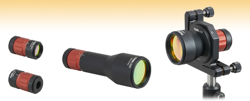
- 2X, 5X, or 10X Beam Expansion
- Sliding Lens Design for Collimation Adjustment
- ZnSe Optics Ideal for CO2 and QCL Laser Applications
- AR Coated for 7 - 12 μm
Output
Input
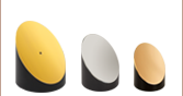
GBE02-E3
2X Magnification
GBE10-E3
10X Magnification
Application Idea
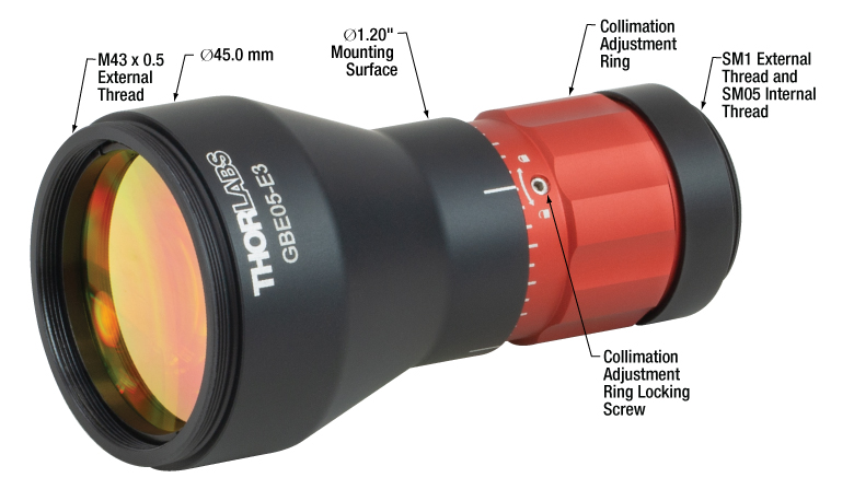
The GBE05-E3 Mounted in a KM200 Kinematic Mount using the SM2A21 Adapter


Please Wait

Click for Details
The 5X magnfication beam expander has an M43 x 0.5-threaded output.
Click for Details
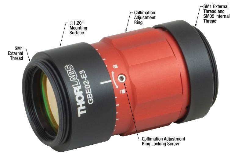
The 2X magnfication beam expander has an SM1-threaded output.
Click for Details
The 10X magnfication beam expander has an M43 x 0.5-threaded output.
Features
- 2X, 5X, or 10X Beam Expansion
- Optics Made from ZnSe Substrate
- Broadband AR Coated for Wavelengths from 7 - 12 μm
- Sliding Lens Collimation Adjustment Minimizes Beam Walk Off
- Housing with Fixed Mechanical Length and Non-Rotating Ends
- Lockable Collimation Adjustment Ring
- Threaded Apertures for Easy Integration into Optical Systems
- Custom Broadband and V Coatings Available (Contact Tech Support)
Thorlabs' Mid-Infrared Beam Expanders can expand or reduce the diameter of a collimated beam by a factor of 2, 5, or 10. These Galilean beam expanders use a low-aberration, air-spaced design optimized to provide a wavefront error of less than λ/4 (i.e., diffraction-limited performance) and minimize the impact on the M2 value of the expanded beam. An expanded beam can be focused to a narrow diffraction-limited waist, allowing an optical system to achieve a higher power density at its focal point.
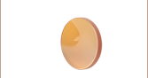
The beam expanders feature lenses with a broadband AR coating optimized for the 7 - 12 μm spectral range to minimize reflections at the air-to-glass interfaces. The optics themselves are made from ZnSe, which is an optical substrate that has a wide transmission band extending from the red portion of the visible spectrum to the mid-IR. As a result, these beam expanders are suitable for applications requiring CO2 lasers, which operate at 10.6 μm, or other infrared sources, like our quantum cascade lasers. See the Specs and AR Coatings tabs for more information on the coating performance. Contact tech support if you require a quote for a custom broadband or V coating to optimize performance in a particular wavelength region.
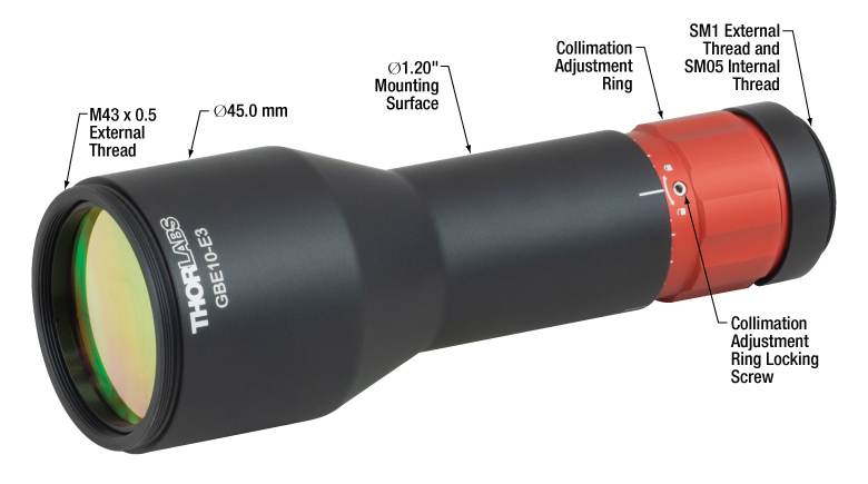
The sliding lens design allows for the collimation to be adjusted while minimizing the beam walk-off effect that is inherent to lens adjustments. The red ring, shown in the photos to the right, adjusts the output beam collimation; once the desired collimation is obtained, the ring can be locked by tightening the locking screw using a 0.05" (1.3 mm) ball driver or hex key (not inlcuded).
Mounting Options
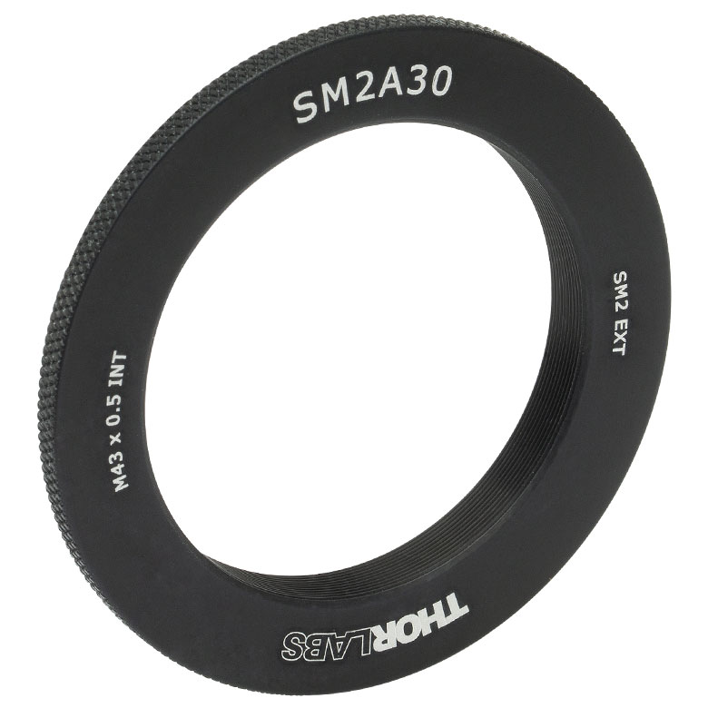
These Galilean beam expanders have threaded input and output apertures, which allow additional lenses and filters to be installed easily along the optical axis of the beam expander. The input of each beam expander has internal SM05 (0.535"-40) and external SM1 (1.035"-40) threads for ease of use with Thorlabs' lens tubes and other optical components. The output of the 2X beam expanders is externally SM1 threaded as well. The beam expanders with 5X or 10X expansion have an externally M43 x 0.5-threaded output, which can be integrated with SM2 (2.035"-40) threaded components by using the SM2A30 adapter. All housings are designed so that the mounting surface and threaded ends do not rotate when turning the collimation adjustment ring, allowing the user to adjust the divergence without disturbing any attached optics and maintain pointing stability.
The Ø1.2" section of the barrel on the 2X, 5X, and 10X beam expanders provides a smooth mounting surface with the same diameter as our Ø1" lens tubes. Below we provide a variety of adapters that allow users to mount these expanders on an optical post, in a cage system, or in a kinematic mount. We also offer the SM1A52 adapter, which allows the input to be mated with components using the M30 x 1.0 thread standard.
Thorlabs offers other fixed magnification beam expanders with UV fused silica optical elements for narrowband applications, achromatic designs for broadband applications, or reflective designs that use mirrors for cases where chromatic aberration is a concern. Variable magnification beam expanders, including our UV fused silica or achromatic zoom beam expanders, are also available. For more information on our extensive line of beam expanders, please see the Beam Expanders tab.
Handling ZnSe Optics
The optics inside the beam expander are made from ZnSe, a hazardous material. For your safety, please follow all proper safety precautions should you need to handle these lenses, including wearing gloves and thoroughly washing your hands afterward. Click here to download a pdf of the MSDS for ZnSe.
Thorlabs will accept all ZnSe lenses back for proper disposal. Please contact Tech Support to make arrangements for this service.
| Item # Prefix | GBE02 | GBE05 | GBE10 | ||
|---|---|---|---|---|---|
| Expansion | 2X | 5X | 10X | ||
| Max Input Beam Diametera | 9.5 mm | 6.7 mm | 3.5 mm | ||
| Diffraction-Limited Input Beam Diametera,b | 9.5 mm | 5.0 mm | 3.5 mm | ||
| Input Thread | Internal: SM05 (0.535"-40) External: SM1 (1.035"-40) |
||||
| Output Thread | External SM1 (1.035"-40) | External M43 x 0.5c | |||
| Typical Total Transmission | 94% | ||||
| Surface Quality | 80-50 Scratch-Dig | ||||
| Housing Dimensions | |||||
| Input Housing Diameter | 30.5 mm (1.20")d | ||||
| Output Housing Diameter | 30.5 mm (1.20")d | 45.0 mm (1.77") | |||
| Housing Length | 52.0 mm (2.05") | 85.5 mm (3.37") | 135.0 mm (5.31") | ||
| Mounting Optionse | SM1RC(/M), SM1TC, CP36, SM2A21 | SM1RC(/M), SM1TC, CP36, SM2A21, SM2A30 | |||
| AR Coating Specifications | |
|---|---|
| Item # Suffix | -E3 |
| AR Coating Range | 7 - 12 μm |
| Average Reflectance per Surfacea | Ravg < 1.0% |
| Absolute Reflectance per Surfacea | Rabs < 2.0% |
| Damage Thresholdb | 5 J/cm2 (10.6 µm, 100 ns, 1 Hz, Ø0.478 mm) |
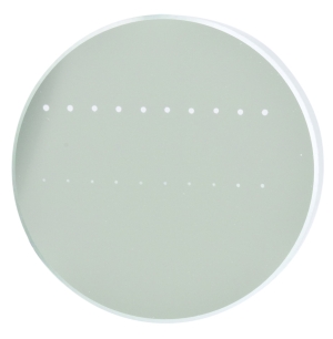
The graph below shows the reflectance per surface with respect to wavelength of the AR coating deposited on both sides of each lens incorporated in our Mid-IR Galilean beam expanders. Each beam expander has two optical elements coated on each side, totaling four coated surfaces. The blue shaded region indicates the wavelength range specified for the -E3 coating. The table below provides the coating specifications.
Click to Enlarge
Click Here for Raw Data
The blue shaded region indicates the specified operating wavlength range for the coating. Performance outside of this region is not guaranteed.
| Antireflection Coating | ||
|---|---|---|
| Item # Suffix | Wavelength Range | Reflectance per Surface |
| -E3 | 7 - 12 μm | Ravg < 1.0% Rabs < 2.0% |
Prolonged use of beam expanders with high-power beams can cause the housing of the beam expander to become hot. The measured temperature rise of our GBE02-E3 and GBE10-E3 mid-infrared beam expanders during use with high-power CW beams is shown in the graphs below. A CW CO2 laser operating at 10.6 µm with powers of 80 W and 200 W was applied for separate trials of 40 minutes each. The input beam had a diameter of 9.5 mm for the trials with the GBE02-E3 and a diameter of 3.5 mm for the trials with the GBE10-E3. Thermocouples were attached at both the input and output sides of the beam expanders while a third thermocouple was placed in air to record the ambient room temperature.
After 40 minutes of use with an 80 W beam, the temperature of the GBE02-E3 housing reached a temperature of ~36 °C, while the GBE10-E3 housing reached a temperature of ~34 °C. With a 200 W beam, the GBE02-E3 housing reached a temperature of ~55 °C and the GBE10-E3 housing reached a temperature of 63 °C. For reference, the average internal body temperature is 37 °C. Care should thus be exercised if using the beam expanders for long periods of time with very high-power beams.
The raw data for these measurements is available by clicking here.
 Click to Enlarge
 Click to Enlarge
 Click to Enlarge
 Click to Enlarge
| Damage Threshold Specifications | |
|---|---|
| Item # Suffix | Damage Threshold |
| -E3 | 5 J/cm2 (10.6 µm, 100 ns, 1 Hz, Ø0.478 mm) |
Damage Threshold Data for Thorlabs' Mid-IR Galilean Beam Expanders
The specifications to the right are measured data for Thorlabs' Mid-IR Galilean Beam Expanders. This is the damage threshold of the AR coating, which limits the power that the beam expander can accept. Note that if these items are being used to reduce the size of a beam, the power at the exit aperture must not exceed this damage threshold.
Laser Induced Damage Threshold Tutorial
The following is a general overview of how laser induced damage thresholds are measured and how the values may be utilized in determining the appropriateness of an optic for a given application. When choosing optics, it is important to understand the Laser Induced Damage Threshold (LIDT) of the optics being used. The LIDT for an optic greatly depends on the type of laser you are using. Continuous wave (CW) lasers typically cause damage from thermal effects (absorption either in the coating or in the substrate). Pulsed lasers, on the other hand, often strip electrons from the lattice structure of an optic before causing thermal damage. Note that the guideline presented here assumes room temperature operation and optics in new condition (i.e., within scratch-dig spec, surface free of contamination, etc.). Because dust or other particles on the surface of an optic can cause damage at lower thresholds, we recommend keeping surfaces clean and free of debris. For more information on cleaning optics, please see our Optics Cleaning tutorial.
Testing Method
Thorlabs' LIDT testing is done in compliance with ISO/DIS 11254 and ISO 21254 specifications.
First, a low-power/energy beam is directed to the optic under test. The optic is exposed in 10 locations to this laser beam for 30 seconds (CW) or for a number of pulses (pulse repetition frequency specified). After exposure, the optic is examined by a microscope (~100X magnification) for any visible damage. The number of locations that are damaged at a particular power/energy level is recorded. Next, the power/energy is either increased or decreased and the optic is exposed at 10 new locations. This process is repeated until damage is observed. The damage threshold is then assigned to be the highest power/energy that the optic can withstand without causing damage. A histogram such as that below represents the testing of one BB1-E02 mirror.
The photograph above is a protected aluminum-coated mirror after LIDT testing. In this particular test, it handled 0.43 J/cm2 (1064 nm, 10 ns pulse, 10 Hz, Ø1.000 mm) before damage.
| Example Test Data | |||
|---|---|---|---|
| Fluence | # of Tested Locations | Locations with Damage | Locations Without Damage |
| 1.50 J/cm2 | 10 | 0 | 10 |
| 1.75 J/cm2 | 10 | 0 | 10 |
| 2.00 J/cm2 | 10 | 0 | 10 |
| 2.25 J/cm2 | 10 | 1 | 9 |
| 3.00 J/cm2 | 10 | 1 | 9 |
| 5.00 J/cm2 | 10 | 9 | 1 |
According to the test, the damage threshold of the mirror was 2.00 J/cm2 (532 nm, 10 ns pulse, 10 Hz, Ø0.803 mm). Please keep in mind that these tests are performed on clean optics, as dirt and contamination can significantly lower the damage threshold of a component. While the test results are only representative of one coating run, Thorlabs specifies damage threshold values that account for coating variances.
Continuous Wave and Long-Pulse Lasers
When an optic is damaged by a continuous wave (CW) laser, it is usually due to the melting of the surface as a result of absorbing the laser's energy or damage to the optical coating (antireflection) [1]. Pulsed lasers with pulse lengths longer than 1 µs can be treated as CW lasers for LIDT discussions.
When pulse lengths are between 1 ns and 1 µs, laser-induced damage can occur either because of absorption or a dielectric breakdown (therefore, a user must check both CW and pulsed LIDT). Absorption is either due to an intrinsic property of the optic or due to surface irregularities; thus LIDT values are only valid for optics meeting or exceeding the surface quality specifications given by a manufacturer. While many optics can handle high power CW lasers, cemented (e.g., achromatic doublets) or highly absorptive (e.g., ND filters) optics tend to have lower CW damage thresholds. These lower thresholds are due to absorption or scattering in the cement or metal coating.
LIDT in linear power density vs. pulse length and spot size. For long pulses to CW, linear power density becomes a constant with spot size. This graph was obtained from [1].
Pulsed lasers with high pulse repetition frequencies (PRF) may behave similarly to CW beams. Unfortunately, this is highly dependent on factors such as absorption and thermal diffusivity, so there is no reliable method for determining when a high PRF laser will damage an optic due to thermal effects. For beams with a high PRF both the average and peak powers must be compared to the equivalent CW power. Additionally, for highly transparent materials, there is little to no drop in the LIDT with increasing PRF.
In order to use the specified CW damage threshold of an optic, it is necessary to know the following:
- Wavelength of your laser
- Beam diameter of your beam (1/e2)
- Approximate intensity profile of your beam (e.g., Gaussian)
- Linear power density of your beam (total power divided by 1/e2 beam diameter)
Thorlabs expresses LIDT for CW lasers as a linear power density measured in W/cm. In this regime, the LIDT given as a linear power density can be applied to any beam diameter; one does not need to compute an adjusted LIDT to adjust for changes in spot size, as demonstrated by the graph to the right. Average linear power density can be calculated using the equation below.

The calculation above assumes a uniform beam intensity profile. You must now consider hotspots in the beam or other non-uniform intensity profiles and roughly calculate a maximum power density. For reference, a Gaussian beam typically has a maximum power density that is twice that of the uniform beam (see lower right).
Now compare the maximum power density to that which is specified as the LIDT for the optic. If the optic was tested at a wavelength other than your operating wavelength, the damage threshold must be scaled appropriately. A good rule of thumb is that the damage threshold has a linear relationship with wavelength such that as you move to shorter wavelengths, the damage threshold decreases (i.e., a LIDT of 10 W/cm at 1310 nm scales to 5 W/cm at 655 nm):

While this rule of thumb provides a general trend, it is not a quantitative analysis of LIDT vs wavelength. In CW applications, for instance, damage scales more strongly with absorption in the coating and substrate, which does not necessarily scale well with wavelength. While the above procedure provides a good rule of thumb for LIDT values, please contact Tech Support if your wavelength is different from the specified LIDT wavelength. If your power density is less than the adjusted LIDT of the optic, then the optic should work for your application.
Please note that we have a buffer built in between the specified damage thresholds online and the tests which we have done, which accommodates variation between batches. Upon request, we can provide individual test information and a testing certificate. The damage analysis will be carried out on a similar optic (customer's optic will not be damaged). Testing may result in additional costs or lead times. Contact Tech Support for more information.
Pulsed Lasers
As previously stated, pulsed lasers typically induce a different type of damage to the optic than CW lasers. Pulsed lasers often do not heat the optic enough to damage it; instead, pulsed lasers produce strong electric fields capable of inducing dielectric breakdown in the material. Unfortunately, it can be very difficult to compare the LIDT specification of an optic to your laser. There are multiple regimes in which a pulsed laser can damage an optic and this is based on the laser's pulse length. The highlighted columns in the table below outline the relevant pulse lengths for our specified LIDT values.
Pulses shorter than 10-9 s cannot be compared to our specified LIDT values with much reliability. In this ultra-short-pulse regime various mechanics, such as multiphoton-avalanche ionization, take over as the predominate damage mechanism [2]. In contrast, pulses between 10-7 s and 10-4 s may cause damage to an optic either because of dielectric breakdown or thermal effects. This means that both CW and pulsed damage thresholds must be compared to the laser beam to determine whether the optic is suitable for your application.
| Pulse Duration | t < 10-9 s | 10-9 < t < 10-7 s | 10-7 < t < 10-4 s | t > 10-4 s |
|---|---|---|---|---|
| Damage Mechanism | Avalanche Ionization | Dielectric Breakdown | Dielectric Breakdown or Thermal | Thermal |
| Relevant Damage Specification | No Comparison (See Above) | Pulsed | Pulsed and CW | CW |
When comparing an LIDT specified for a pulsed laser to your laser, it is essential to know the following:
LIDT in energy density vs. pulse length and spot size. For short pulses, energy density becomes a constant with spot size. This graph was obtained from [1].
- Wavelength of your laser
- Energy density of your beam (total energy divided by 1/e2 area)
- Pulse length of your laser
- Pulse repetition frequency (prf) of your laser
- Beam diameter of your laser (1/e2 )
- Approximate intensity profile of your beam (e.g., Gaussian)
The energy density of your beam should be calculated in terms of J/cm2. The graph to the right shows why expressing the LIDT as an energy density provides the best metric for short pulse sources. In this regime, the LIDT given as an energy density can be applied to any beam diameter; one does not need to compute an adjusted LIDT to adjust for changes in spot size. This calculation assumes a uniform beam intensity profile. You must now adjust this energy density to account for hotspots or other nonuniform intensity profiles and roughly calculate a maximum energy density. For reference a Gaussian beam typically has a maximum energy density that is twice that of the 1/e2 beam.
Now compare the maximum energy density to that which is specified as the LIDT for the optic. If the optic was tested at a wavelength other than your operating wavelength, the damage threshold must be scaled appropriately [3]. A good rule of thumb is that the damage threshold has an inverse square root relationship with wavelength such that as you move to shorter wavelengths, the damage threshold decreases (i.e., a LIDT of 1 J/cm2 at 1064 nm scales to 0.7 J/cm2 at 532 nm):

You now have a wavelength-adjusted energy density, which you will use in the following step.
Beam diameter is also important to know when comparing damage thresholds. While the LIDT, when expressed in units of J/cm², scales independently of spot size; large beam sizes are more likely to illuminate a larger number of defects which can lead to greater variances in the LIDT [4]. For data presented here, a <1 mm beam size was used to measure the LIDT. For beams sizes greater than 5 mm, the LIDT (J/cm2) will not scale independently of beam diameter due to the larger size beam exposing more defects.
The pulse length must now be compensated for. The longer the pulse duration, the more energy the optic can handle. For pulse widths between 1 - 100 ns, an approximation is as follows:

Use this formula to calculate the Adjusted LIDT for an optic based on your pulse length. If your maximum energy density is less than this adjusted LIDT maximum energy density, then the optic should be suitable for your application. Keep in mind that this calculation is only used for pulses between 10-9 s and 10-7 s. For pulses between 10-7 s and 10-4 s, the CW LIDT must also be checked before deeming the optic appropriate for your application.
Please note that we have a buffer built in between the specified damage thresholds online and the tests which we have done, which accommodates variation between batches. Upon request, we can provide individual test information and a testing certificate. Contact Tech Support for more information.
[1] R. M. Wood, Optics and Laser Tech. 29, 517 (1998).
[2] Roger M. Wood, Laser-Induced Damage of Optical Materials (Institute of Physics Publishing, Philadelphia, PA, 2003).
[3] C. W. Carr et al., Phys. Rev. Lett. 91, 127402 (2003).
[4] N. Bloembergen, Appl. Opt. 12, 661 (1973).

In order to illustrate the process of determining whether a given laser system will damage an optic, a number of example calculations of laser induced damage threshold are given below. For assistance with performing similar calculations, we provide a spreadsheet calculator that can be downloaded by clicking the LIDT Calculator button. To use the calculator, enter the specified LIDT value of the optic under consideration and the relevant parameters of your laser system in the green boxes. The spreadsheet will then calculate a linear power density for CW and pulsed systems, as well as an energy density value for pulsed systems. These values are used to calculate adjusted, scaled LIDT values for the optics based on accepted scaling laws. This calculator assumes a Gaussian beam profile, so a correction factor must be introduced for other beam shapes (uniform, etc.). The LIDT scaling laws are determined from empirical relationships; their accuracy is not guaranteed. Remember that absorption by optics or coatings can significantly reduce LIDT in some spectral regions. These LIDT values are not valid for ultrashort pulses less than one nanosecond in duration.
Figure 71A A Gaussian beam profile has about twice the maximum intensity of a uniform beam profile.
CW Laser Example
Suppose that a CW laser system at 1319 nm produces a 0.5 W Gaussian beam that has a 1/e2 diameter of 10 mm. A naive calculation of the average linear power density of this beam would yield a value of 0.5 W/cm, given by the total power divided by the beam diameter:
However, the maximum power density of a Gaussian beam is about twice the maximum power density of a uniform beam, as shown in Figure 71A. Therefore, a more accurate determination of the maximum linear power density of the system is 1 W/cm.
An AC127-030-C achromatic doublet lens has a specified CW LIDT of 350 W/cm, as tested at 1550 nm. CW damage threshold values typically scale directly with the wavelength of the laser source, so this yields an adjusted LIDT value:
The adjusted LIDT value of 350 W/cm x (1319 nm / 1550 nm) = 298 W/cm is significantly higher than the calculated maximum linear power density of the laser system, so it would be safe to use this doublet lens for this application.
Pulsed Nanosecond Laser Example: Scaling for Different Pulse Durations
Suppose that a pulsed Nd:YAG laser system is frequency tripled to produce a 10 Hz output, consisting of 2 ns output pulses at 355 nm, each with 1 J of energy, in a Gaussian beam with a 1.9 cm beam diameter (1/e2). The average energy density of each pulse is found by dividing the pulse energy by the beam area:
As described above, the maximum energy density of a Gaussian beam is about twice the average energy density. So, the maximum energy density of this beam is ~0.7 J/cm2.
The energy density of the beam can be compared to the LIDT values of 1 J/cm2 and 3.5 J/cm2 for a BB1-E01 broadband dielectric mirror and an NB1-K08 Nd:YAG laser line mirror, respectively. Both of these LIDT values, while measured at 355 nm, were determined with a 10 ns pulsed laser at 10 Hz. Therefore, an adjustment must be applied for the shorter pulse duration of the system under consideration. As described on the previous tab, LIDT values in the nanosecond pulse regime scale with the square root of the laser pulse duration:
This adjustment factor results in LIDT values of 0.45 J/cm2 for the BB1-E01 broadband mirror and 1.6 J/cm2 for the Nd:YAG laser line mirror, which are to be compared with the 0.7 J/cm2 maximum energy density of the beam. While the broadband mirror would likely be damaged by the laser, the more specialized laser line mirror is appropriate for use with this system.
Pulsed Nanosecond Laser Example: Scaling for Different Wavelengths
Suppose that a pulsed laser system emits 10 ns pulses at 2.5 Hz, each with 100 mJ of energy at 1064 nm in a 16 mm diameter beam (1/e2) that must be attenuated with a neutral density filter. For a Gaussian output, these specifications result in a maximum energy density of 0.1 J/cm2. The damage threshold of an NDUV10A Ø25 mm, OD 1.0, reflective neutral density filter is 0.05 J/cm2 for 10 ns pulses at 355 nm, while the damage threshold of the similar NE10A absorptive filter is 10 J/cm2 for 10 ns pulses at 532 nm. As described on the previous tab, the LIDT value of an optic scales with the square root of the wavelength in the nanosecond pulse regime:
This scaling gives adjusted LIDT values of 0.08 J/cm2 for the reflective filter and 14 J/cm2 for the absorptive filter. In this case, the absorptive filter is the best choice in order to avoid optical damage.
Pulsed Microsecond Laser Example
Consider a laser system that produces 1 µs pulses, each containing 150 µJ of energy at a repetition rate of 50 kHz, resulting in a relatively high duty cycle of 5%. This system falls somewhere between the regimes of CW and pulsed laser induced damage, and could potentially damage an optic by mechanisms associated with either regime. As a result, both CW and pulsed LIDT values must be compared to the properties of the laser system to ensure safe operation.
If this relatively long-pulse laser emits a Gaussian 12.7 mm diameter beam (1/e2) at 980 nm, then the resulting output has a linear power density of 5.9 W/cm and an energy density of 1.2 x 10⁻⁴ J/cm2 per pulse. This can be compared to the LIDT values for a WPQ10E-980 polymer zero-order quarter-wave plate, which are 5 W/cm for CW radiation at 810 nm and 5 J/cm2 for a 10 ns pulse at 810 nm. As before, the CW LIDT of the optic scales linearly with the laser wavelength, resulting in an adjusted CW value of 6 W/cm at 980 nm. On the other hand, the pulsed LIDT scales with the square root of the laser wavelength and the square root of the pulse duration, resulting in an adjusted value of 55 J/cm2 for a 1 µs pulse at 980 nm. The pulsed LIDT of the optic is significantly greater than the energy density of the laser pulse, so individual pulses will not damage the wave plate. However, the large average linear power density of the laser system may cause thermal damage to the optic, much like a high-power CW beam.
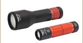
Click to Enlarge
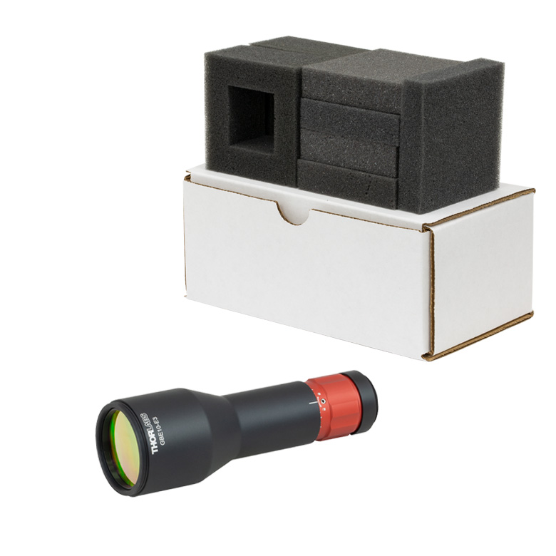
Old Beam Expander Packaging
Click to Enlarge
New Beam Expander Packaging
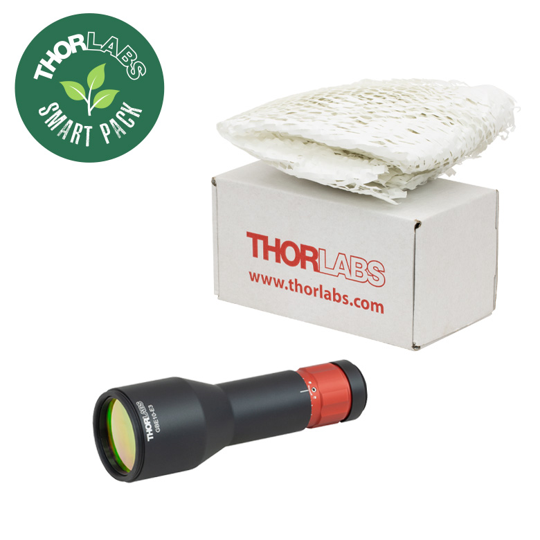
Smart Pack Goals
- Reduce Weight of Packaging
- Increase Usage of Recyclable Materials
- Improve Packing Integrity
- Decrease Shipping Costs
Thorlabs' Smart Pack Initiative is aimed at minimizing waste while providing adequate protection for our products. By eliminating any unnecessary packaging, implementing design changes, and utilizing eco-friendly materials, this initiative seeks to reduce the environmental impact of our product packaging.
The new fixed magnification beam expanders packaging is made from over 60% recycled paper products and weighs
25.44 g less than the old packaging. The transition from foam and non-recycled paper to recycled paper products results in a 68.05% reduction in the amount of CO2 produced per kg of packing materials. All products on this page have transitioned, or are in the process of transitioning to recycled paper.
As we move through our product line, we will indicate re-engineered, eco-friendly packaging with our Smart Pack logo, which can be seen in the image to the right.
| Posted Comments: | |
Nate Hough
(posted 2023-12-01 09:40:31.133) Could these beam expanders be made with Si or BaF2 optics and optimized for the 2-5um band? Looks like these are labeled mid-IR but the 7-12um band is usually referred to as long wave-IR. fnero
(posted 2023-12-04 04:15:40.0) Thank you for your feedback. At the moment, the only beam expanders we have for the the wavelength range 2-5um, are the reflective beam expanders, available here, https://www.thorlabs.com/newgrouppage9.cfm?objectgroup_id=4089. We have reached out to you to further discuss your application. Jungwook Kim
(posted 2022-09-30 14:01:37.697) Can you provide the LIDT for CW? We are using 9.6 um CO2 laser. jgreschler
(posted 2022-10-17 03:30:11.0) Thank you for reaching out to Thorlabs. We do not currently have LIDT data for this product at 9.6um. Additional specs and data can be requested by emailing techsupport@thorlabs.com. I have reached out to you directly to discuss this further. |
Thorlabs offers fixed magnification beam expanders, as well as zoom beam expanders that do not need to be refocused when the magnification is adjusted since the collimation remains constant. The tables on this tab provide a direct comparison of the options we offer. Please contact Tech Support if you would like help choosing the best beam expander for your specific application.
| Beam Expander Description |
Fixed Magnification UVFS Laser Line, Sliding Lens |
Fixed Magnification Achromatic, Sliding Lens |
Fixed Magnification Mid-Infrared, Sliding Lens |
|---|---|---|---|
| Expansions Available | 2X, 3X, 5X, 10X, 20Xa | 2X, 3X, 5X, 10X, 15X, 20X |
2X, 5X, 10X |
| AR Coating Range(s) (Item # Suffix) |
240 - 360 nm (-UVB) 248 - 287 nm (-266) 325 - 380 nm (-355) 488 - 580 nm (-532) 960 - 1064 nm (-1064) |
400 - 650 nm (-A) 650 - 1050 nm (-B) 1050 - 1650 nm (-C) |
7 - 12 μm (-E3) |
| Mirror Coating (Range) | N/A | ||
| Reflectance (per Surface) | Rmax < 1.5% (-UVB) Ravg < 0.2% (All Others) |
Rmax < 0.5% | Ravg < 1.0% |
| Max Input Beam Diameter | 2X: 8.5 mm 3X: 9.0 mm 5X: 4.3 mm 10X: 2.8 mm 20X: 2.0 mm |
2X: 8.5 mm 3X: 9.0 mm 5X: 5.0 mm 10X: 3.0 mm 15X: 2.5 mm 20X: 2.0 mm |
2X: 9.5 mm 5X: 6.7 mm 10X: 3.5 mm |
| Wavefront Error | <λ/4 (Peak to Valley) | ||
| Surface Quality | 10-5 Scratch-Dig | 20-10 Scratch-Dig | 80-50 Scratch-Dig |
| Beam Expander Description |
Zoom UVFS, Sliding Lens |
Zoom Achromatic, Sliding Lens |
Reflective Beam Expander Fixed Magnification |
|---|---|---|---|
| Expansions Available | 0.5X - 2.5X, 1X - 4X, 2X - 8X, 4X - 16X |
0.5X - 2.5X, 1X - 4X, 2X - 8X, 4X - 16X |
2X, 4X, 6X |
| AR Coating Range(s) (Item # Suffix) |
240 - 360 nm (UVB) 330 - 370 nm (3) 495 - 570 nm (2) 980 - 1130 nm (1) |
400 - 650 nm (A) 650 - 1050 nm (B) 1050 - 1650 nm (C) |
N/A |
| Mirror Coating (Range) | N/A | Protected Silver (450 nm - 20 μm) |
|
| Rmax < 1.5% for (UVB) Ravg < 0.2% (All Others) |
Rmax < 0.5% | Ravg > 95% | |
| Max Input Beam Diameter | 0.5X - 2.5X: 10.9 to 8.0 mm 1X - 4X: 10.9 to 8.8 mm 2X - 8X: 6.0 to 4.4 mm 4X - 16X: 6.0 to 2.7 mm |
0.5X - 2.5X: 10.9 to 8.0 mm 1X - 4X: 10.9 to 8.8 mm 2X - 8X: 6.0 to 4.4 mm 4X - 16X: 6.0 to 2.7 mm |
3 mm |
| Wavefront Error | <λ/4 (Peak to Valley) | <λ/10a (RMS) | |
| Surface Quality | 10-5 Scratch-Dig | 20-10 Scratch-Dig | 40-20 Scratch-Dig |
| Item # | Expansion | Max Input Beam Diameter |
Diffraction-Limited Input Beam Diametera |
Input Thread | Output Thread (External) |
AR Coating Reflectance |
Typical Transmission |
Damage Thresholdb |
|---|---|---|---|---|---|---|---|---|
| GBE02-E3 | 2X | 9.5 mm | 9.5 mm | Internal: SM05 External: SM1 |
SM1 | Ravg < 1.0% Rabs < 2.0% for 7 - 12 μm |
94% | 5 J/cm2 (10.6 µm, 100 ns, 1 Hz, Ø0.478 mm) |
| GBE05-E3 | 5X | 6.7 mm | 5.0 mm | M43 x 0.5c | ||||
| GBE10-E3 | 10X | 3.5 mm | 3.5 mm |
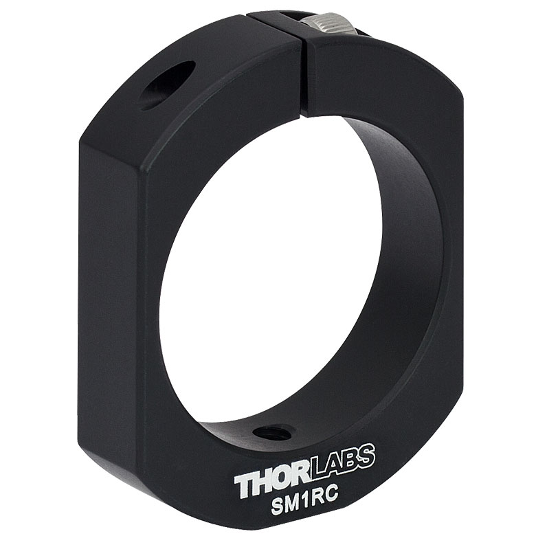
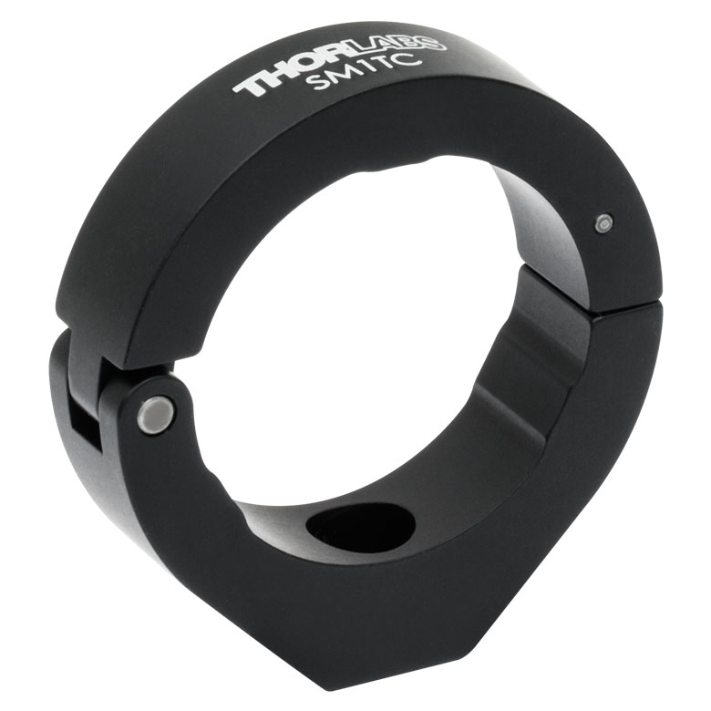
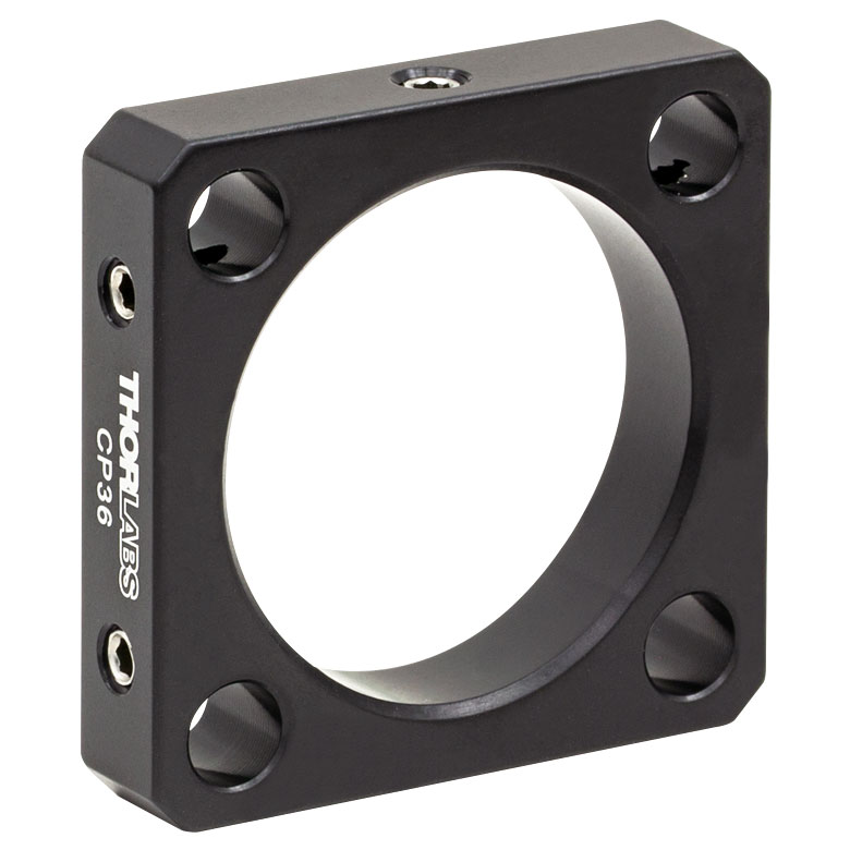
Several mounting options for the Mid-IR Beam Expanders are provided in the table below. For our complete selection of thread adapters, see our Optical Component Thread Adapters selection guide.
| Item # | SM1RC(/M) | SM1TC | CP36 | SM2A21 | SM2A30 |
|---|---|---|---|---|---|
| Photo (Click to Enlarge) |
 |
 |
 |
 |
 |
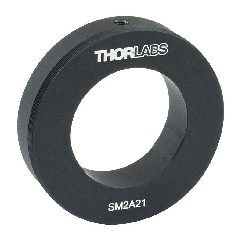
| Application | Slip Ring for Post Mounting | Clamp for Post Mounting | 30 mm Cage Mount for Ø1.2" Housing | Mount Beam Expander in Ø2" or SM2-Threaded Optic Mounts |
Integrate Beam Expander with SM2-Threaded Components |
| Compatible MidIR Beam Expanders (Item # Prefix) | GBE02 GBE05 GBE10 |
GBE02 GBE05 GBE10 |
GBE02 GBE05a GBE10a |
GBE02 GBE05 GBE10 |
GBE05 GBE10 |
| Internal Bore / Threads |
Ø1.2" Bore | Ø1.2" Bore | Ø1.2" Bore | Ø1.2" Bore | M43 x 0.5 Threads |
| - | - | - | SM2 Threads and Ø2" Smooth Surface |
SM2 Threads | |
| Mounting Holes | 8-32 (M4) Tap | #8 (M4) Counterbore | Compatible with 30 mm Cage Systems |
- | - |