 Products Home / Fiber Components / Fiber Polarization Management / In-Line Fiber Optic Polarization Controllers
In-Line Fiber Optic Polarization Controllers
- Converts an Arbitrary Input Polarization State to Any Desired Output Polarization State
- Insensitive to Wavelength Variations, Vibrations, and Fiber Variations
- Versions for Ø250 µm Bare Fiber or Ø900 μm Tight-Buffer Fiber
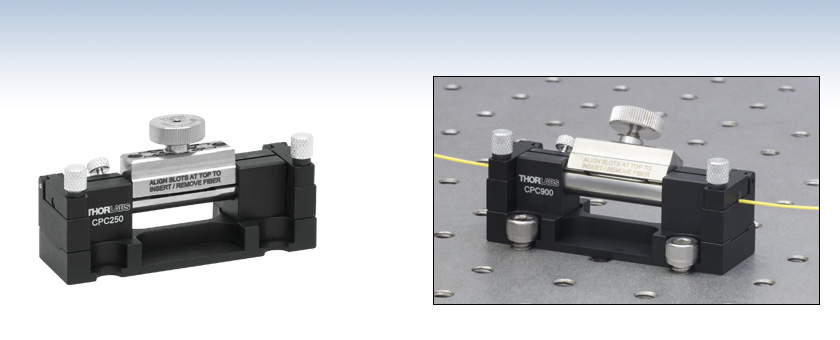
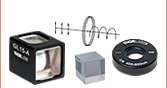
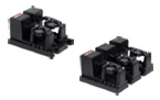
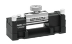
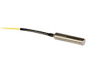
CPC250
Polarization Controller for Ø250 µm Bare Fiber
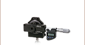
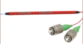
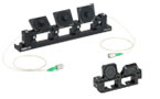
CPC900 with Ø900 µm Tight-Buffer Fiber Mounted on an Optical Table


Please Wait

Features
- Fiber Squeezer Design Creates an In-Fiber Variable Wave Plate
- Compact Footprint: 0.98" x 2.95"
- OCT-Proven Design
- Versions for Ø250 µm Bare Fiber or Ø900 µm Tight-Buffer Jacketed Fiber
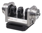
We offer compact, in-line polarization controllers for Ø250 µm bare fiber or Ø900 µm tight-buffer fiber. Each device consists of a rotatable fiber squeezer and two fiber holding clamps. They create stress-induced birefringence within SM fiber by mechanically compressing the fiber. This acts like a variable, rotatable wave plate. Both the angle and retardance of the wave plate can be continuously, independently adjusted, which allows any arbitrary input polarization state to be converted to any desired output polarization state. See the Operation tab for details.
The all-fiber design produces low intrinsic loss and back reflections, making these controllers a good alternative to traditional free-space polarization controllers, which consist of two quarter-wave plates and one half-wave plate. Fiber can be dropped into the devices without disconnecting either end from a setup, and the units can be operated without the use of any tools. The polarization controllers have a compact, 0.98" x 2.95" (24.9 mm x 74.9 mm) footprint with four 1/4" (M6) clearance slots for securing to an optical table with imperial or metric hole spacing. Please note that these controllers are not intended for use with loose-tube furcation tubing.
Thorlabs offers single mode fiber and fiber patch cables with a Ø900 µm jacket for use with these controllers.
| Fiber Polarization Control Selection Guide | ||||||
|---|---|---|---|---|---|---|
| Polarization Controllers | Linear Polarizers | |||||
 |
 |
 |
 |
 |
 |
 |
| Motorized Fiber Polarization Controllers | Manual Paddle Fiber Polarization Controllers | In-Line Manual Fiber Polarization Controller | Free-Space FiberBench | Faraday Mirrors | In-Line Fiber Polarizers | Polarizing Fiber |
Click to Enlarge
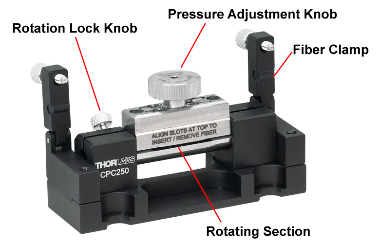
Figure 2.1 Features of the In-Line Fiber Polarization Controller
Figure 2.2 f and s correspond to the fast and slow axes, respectively, of the fiber wave plate. They define a coordinate system used in the calculations below. (a) The squeezing force on the fiber creates stress-induced birefringence, creating a wave plate. (b) The fiber can be twisted to rotate the fast and slow axes of the wave plate.
Recommended Adjustment Procedure
Each Fiber Polarization Controller consists of two fiber holding clamps with a rotatable fiber squeezer mounted between them. The procedure below details how to convert an unknown, arbitrary elliptical input polarization state (common in single mode fiber) to a linear output polarization state, to be input into a polarization-sensitive optical device.
To insert the fiber into a polarization controller, open the two fiber holding clamps by unscrewing the locking screws and raising the clamp arms. Rotate the center section to align the slots along the top of the device. Close the fiber clamps and tighten the screws to secure the fiber in place. Rotate the center section until the thumbscrew (pressure adjustment knob) is upright before tightening the thumbscrew.
Monitor the output polarization state with a polarizer and a power meter, or with a polarimeter.
Tighten the pressure adjustment knob to apply pressure to the center portion of the fiber. If this causes a significant increase in the monitored optical power, then continue to increase pressure until the optical power starts to decrease. If applying pressure initially causes the monitored optical power to decrease or remain the same, loosen the pressure adjustment knob and rotate the center section in order to compress the fiber in a different direction. For increased control over the amount of pressure applied, the pressure adjustment knob includes a slot for use with the included 5/64" (2.0 mm) hex key.
Rotate the fiber squeezer while maintaining the pressure to fine tune the output polarization. Adjust the pressure and orientation of the rotatable fiber squeezer iteratively until a maximum optical power is obtained. This indicates that the desired polarization is achieved.
Fiber Polarization Control
The pressure applied by the fiber squeezer produces a linear birefringence in a short section of the fiber, which creates a fiber wave plate. The amount of birefringence per unit length, δ, is proportional to the applied pressure and is given by
where F is the applied force in newtons, λ is the wavelength of light in meters, and d is the diameter of the fiber in meters.1, 2
The fiber's core acts as a birefringent wave plate with a slow axis that is defined by the direction of the applied pressure, as shown in Figure 2.2 (a). By changing the applied pressure, the retardation of the fiber wave plate can be continuously varied between 0 and 2π.
Rotating the fiber squeezer while applying pressure causes the birefringent portion of the fiber to rotate. This also causes the fiber at the left and right sides of the birefringent section to twist. This twisted fiber rotates the incident polarization in the direction of the twist by an angle given by

where θ is the physical rotation angle shown in Figure 2.2 (b) and η is a coefficient of twist-induced optical activity. For single mode fibers, η is on the order of 0.083, 4, 5. For a physical rotation of θ degrees, the net change of the incident angle between the slow axis of the fiber wave plate and the input polarization, in degrees, is

For coarse angular adjustments, the fiber squeezer should be rotated without twisting the fiber. This can be accomplished by releasing the pressure from the fiber squeezer before rotating it. Once the desired rotation is achieved, pressure can be reapplied by the fiber squeezer. Thus, for a physical rotation of θ degrees, the net change of the incident angle between the slow axis of the fiber wave plate and the input polarization is also θ degrees.
We recommend this procedure for the coarse adjustment of the output polarization state. When the output polarization is close to that desired, the fiber squeezer can be rotated slightly while applying pressure in order to fine tune the output polarization angle.
Achieving the Desired Output Polarization State
The rotatable fiber squeezer allows the optical fiber to act as a wave plate of variable retardation and rotatable birefringent axes. This is equivalent to a Soleil-Babinet compensator6. Using the slow and fast axes of fiber wave plate as a coordinate system, as shown in Figure 2.2, the Jones matrix describing the birefringence of the fiber wave plate can be written as
where  is the phase retardation of the fiber. In this expression, l is the length of the birefringent fiber and Δn is the index of refraction difference between the slow and fast axes. In the same coordinate system, the Jones vector of an arbitrary input polarization is
where Es and Ef are the amplitudes of the light field projected on the slow and fast axes, respectively, φ is the phase retardation between Es and Ef, , and
, and  .
.
After propagation through the squeezed fiber, the Jones vector of the output polarization state is
where  . The birefringent axis of the fiber can be rotated, and thus α can be continuously varied from 0 to π/2. Similarly, the phase retardation, Γ, can be continuously varied from 0 to 2π by changing the pressure on the fiber. Thus, χ can take any value on the complex plane Re(χ) vs. Im(χ). Because each point of the complex plane is associated with a polarization state7, the rotatable fiber squeezer is capable of generating any output polarization from any arbitrary input polarization.
References
- A. M. Smith, "Single-mode fiber pressure sensitivity," Electronics Letters, Vol. 16, No 20, pp 773-774 (1980).
- J. Sakai and T. Kimura, "Birefringence and Polarization Characteristics of Single-Mode Optical Fibers under Elastic Deformations," IEEE Journal of Quantum Electronics, Vol. QE-17, No. 6, pp 1041-1051 (1981).
- R. Ulrich and A. Simon, "Polarization optics of twisted single-mode fibers," Applied Optics, Vol. 18, No. 13, pp 2241-2251 (1979).
- A. Smith, "Birefringence induced by bends and twists in single-mode optical fiber," Applied Optics, Vol. 19, No. 15, pp 2060-2611 (1980).
- M. Monerie and L. Jeunhomme, "Polarization mode coupling in long single-mode fibers," Optical and Quantum Electronics, Vol. 12, pp 449-461 (1980).
- M. Born and E. Wolf, Principles of Optics, New York: Pergamon Press, Sixth edition, 1980, pp. 693-694.
- A. Yariv and P. Yeh, Optical Waves in Crystals, New York: John Wiley & Sons, 1984, pp. 61-62.
Click to Enlarge
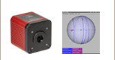
Figure 3.2 Poincaré sphere showing the polarization rotation from the polarization controller.
Click to Enlarge
Figure 3.1 Forces produced by the polarization controller.
Thorlabs Lab Fact: Using the In-Line Fiber Optic Polarization Controller
We present laboratory measurements of the influence on the output polarization state from a fiber due to rotational and compression forces from the former generation PLC-900 polarization controller. The CPC900 performs in the same way as the PLC-900. The CPC250 performs similarly as well, but it accepts Ø250 µm bare fiber. The controller utilizes the effects of stress-induced birefringence to create changes in the polarization of light traveling through a fiber under stress. The stress can be caused either through compression [1] or rotation [2], as shown in Figure 3.1. It was found that the stress-induced birefringence can be adjusted continuously, thus allowing any arbitrary input polarization state to be rotated into any desired output polarization state. We detail the procedures necessary to achieve a desired output polarization, and plot the change in the polarization on a Poincaré sphere to illustrate the steps necessary in reaching a desired polarization state.
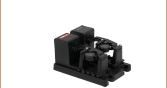
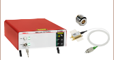
For our experiment, we used the previous-generation S1FC1310 Fabry-Perot Benchtop Laser (1310 nm) as the light source and coupled it into a Ø900 µm tight-buffer fiber. The fiber is mounted through the PLC-900, and the output was collimated into a free-space beam with a fiber collimator. From here the beam was measured, either directly by a polarimeter or through an analyzer assembly consisting of a λ/4 wave plate, a linear polarizer, and a power meter.

Figure 3.2 summarizes the measured results for manipulating the polarization of light in a fiber as a function of rotational and compression forces and is shown on the Poincaré sphere. The blue lines represent compression and the red lines represent rotation of the PLC-900 (see Figure 3.1); the numbers indicate the step. As shown in Figure 3.2, starting at any arbitrary polarization state, it is possible to achieve any desired polarization state through a series of rotations and compressions. This manipulation of the polarization by the PLC-900 does not produce intrinsic loss nor back reflections; instead stress-induced birefringence is utilized as a mechanism for rotating the polarization of light in fiber. Data is presented for both compression and rotation forces, and the polarization changes due to these are mapped out on Poincaré spheres. For details on the experimental setup employed and the results obtained, please click here.
[1] A.M. Smith, “Single-mode fibre pressure sensitivity,” Electron Lett. 16, 773-774 (1980).
[2] R. Ulrich, A. Simon, “Polarization optics of twisted single-mode fibers” Appl Opt 18, 2241-2251 (1979).

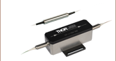
Click to Enlarge
Figure 4.1 CPC250 Packaging

| Item # | % Weight Reduction |
CO2-Equivalent Reductiona |
|---|---|---|
| CPC250 CPC900 |
44.94% | 10.92 kg |
Smart Pack
- Reduce Weight of Packaging Materials
- Increase Usage of Recyclable Packing Materials
- Improve Packing Integrity
- Decrease Shipping Costs
Thorlabs' Smart Pack Initiative is aimed at waste minimization while still maintaining adequate protection for our products. By eliminating any unnecessary packaging, implementing packaging design changes, and utilizing eco-friendly packaging materials for our customers when possible, this initiative seeks to improve the environmental impact of our product packaging. Products listed here are now shipped in re-engineered packaging that minimizes the weight and the use of non-recyclable materials.b As we move through our product line, we will indicate re-engineered packages with our Smart Pack logo.
| Posted Comments: | |
圆 向
(posted 2025-06-25 21:14:49.44) What are the differences between the compact polarizer(CPC250) and the three-piece polarizing element(FPC030)? Also, is the compact type one required to fuse the FC/APC optical fiber heads by oneself? It seems that the description on it doesn't mention the presence of connectors. EGies
(posted 2025-06-26 01:33:41.0) Thank you for contacting Thorlabs. Both use mechanical stress to induce birefringence and alter the output polarization state of light launched into the fiber. While each paddle in a fiber paddle controller can be configured as an independent “waveplate” based on the number of loops and loop size, the in-line controller acts like a singular retarder. Neither the CPC250 nor the FPC030 have fiber pre-loaded. You will need to provide and load your own fiber/fiber patch cables for these controllers. I have reached out to you directly regarding this. user
(posted 2022-10-28 10:19:55.797) I am having an issue with several CPC900's where the pressure adjustment knob becomes very hard to turn or even gets stuck.
The pressure adjustment knob is not at either end of its range of motion and there is currently no fiber in the polarization controller, but I still cannot turn the knob.
Is there a way to fix this issue? Amit Pascal
(posted 2022-03-31 16:38:51.457) using in line polarizer controller.
We are using the in line polarizer controller for a some time, and just now noticed that we are using 900um loose tube and not tight tube. Even though we see that the results are satisfactory.
Can you explain , your recommendation not using loose tube.
Are there any long term effects on the polarization stability when using loose tube instead of tight tube. jgreschler
(posted 2022-04-06 10:42:04.0) Thank you for reaching out to Thorlabs. While your application may functionally work it is not recommended. The length of fiber being compressed is quite small and in order to guarantee good contact of the controller over that length it is recommended you use a tight tube fiber optic cable. Using a loose tube fiber optic cable with this controller we cannot guarantee the contact, therefore the stress values/ performance, of the device. mshishkins
(posted 2018-05-03 14:30:44.92) What is the optical fiber compatible with this component for 405nm? Could you give me a product number for such fiber YLohia
(posted 2018-05-03 09:41:21.0) Hello, the CPC900 is compatible with any fiber that has a Ø900 µm tight-buffer fiber. Unfortunately, the only items we stock that meet this requirement are our SMF-28 type fibers, which are not suited for the visible wavelength range. Please consider using the CPC250 with a bare S405-XP fiber or one of our paddle polarization controllers. skocaman
(posted 2017-09-11 18:57:46.183) Do you have a FC/PC fiber connected version? tfrisch
(posted 2017-09-20 04:58:09.0) Hello, thank you for contacting Thorlabs. While PLC-900 does not come with a fiber, it can be used with FC/PC connectorized fiber. We also offer polarizers integrated with a fiber and connectors here. https://www.thorlabs.com/NewGroupPage9.cfm?ObjectGroup_ID=5922
I will reach out to you to discuss these products. flint
(posted 2014-01-07 18:10:31.647) Could you send me a copy of the Manual for the PLC-900. I would like to understand how it works before I buy it. Thanks! jlow
(posted 2014-01-08 08:11:28.0) Response from Jeremy at Thorlabs: We will send you the documentation and we will work on putting it on the webpage for other customers as well. kornel.jahn
(posted 2013-10-04 07:56:24.39) Dear Sir/Madam,
is there any short guide on how to use the PLC-900 polarization controller? My question is on how to operate it after having inserted the fiber.
Should I first rotate the central part and then squeeze the fiber with the metal screw? Or should I first squeeze the fiber with the metal screw and rotate it afterwards? Thank you in advance.
Best regards,
Kornel Jahn jlow
(posted 2013-10-04 10:14:00.0) Response from Jeremy at Thorlabs: We will send you an application note for operating the PLC-900. bdada
(posted 2012-02-08 18:44:00.0) Response from Buki at Thorlabs to mohamed.esmail:
Thank you for your interest in Thorlabs products. We have contacted you to provide more information. mohamed.esmail
(posted 2012-02-08 08:24:42.0) we have private college of engineering.
Please advise us of what you will quote to make our mind for what you will note quote.
The due date within one week.
Please be informed that it is educational sector which it is supposed to get special discount.
Waiting urgently for your feedback.
Best Regards
Mohamed Esmail
Giza Systems &Services| Education Sector Sales Manager.
Plot #176, Second Sector, City Center, New Cairo 11835,egypt
Phone: +20 2 2614 6000 Phone +(202) 37608801/2 | EXT 3134
Fax: +20 2 2614 6001, +(202) 37603247 : +20 2 37615085
Mobile: +20 10 jjurado
(posted 2011-07-14 09:50:00.0) Response from Javier at Thorlabs to avle: Thank you for contacting us. We will upload the SolidWorks model for this polarization controller to the web shortly. In the meantime, I will send you this file directly. avle
(posted 2011-07-12 18:15:50.0) is a solidworks model avaliable for this? Thanks! |
| Item # | Compatible Fiber Jacket | Controller-Induced Insertion Loss | Controller-Induced Return Loss | Opearating Temperature | Storage Temperature |
|---|---|---|---|---|---|
| CPC250 | Ø250 µm Bare Fibera | <0.05 dBb | >65 dBb | −40 to 85 °C | −40 to 85 °C |
| CPC900 | Ø900 µm Tight-Buffer Jacketc | <0.05 dBd | >65 dBd |