 Products Home / Optical Fiber & Fiber Patch Cables / Active Rare-Earth Doped Optical Fiber / Ytterbium-Doped PM Optical Fiber
Ytterbium-Doped PM Optical Fiber

- Ytterbium-Doped Polarization-Maintaining Fiber for Fiber Lasers and Amplifiers
- 920 nm Absorption and 1000 - 1100 nm Emission Wavelength Range
- Cladding- or Core-Pumped Single- or Large-Mode-Area
- Matched Passive Fibers Available
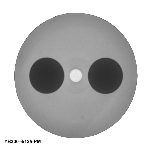
YB1200-10/125DC-PM
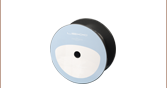
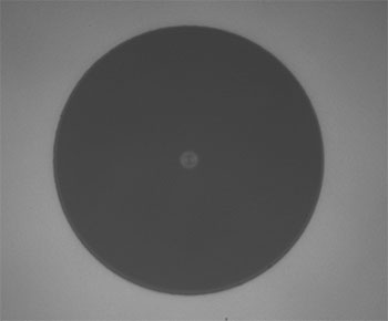
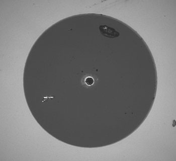
Image of Fiber End Face of an Yb-Doped Active Fiber
Slope Efficiency Plot for a Ytterbium-Doped, Double-Clad Polarization-Maintaining (PM) Fiber


Please Wait
| Item # | Type | Cladding Type |
Absorption @ 920 nm |
Pump Type |
Core Diameter | MFDa | Cladding Diameter |
|---|---|---|---|---|---|---|---|
| YB300-6/125-PM | SMb | Single | 75 ± 10 dB/mc,d | Core | 5.5 µmd | 7.0 ± 0.5 µm | 125 ± 2 µm |
| YB1200-6/125DC-PM | Double | 0.55 ± 0.1 dB/m | Cladding | - | 7.0 ± 0.5 μm | 125 ± 1 μm | |
| YB1200-10/125DC-PM | LMAe | 1.7 ± 0.3 dB/m | 10.0 ± 1.0 μm | - | |||
| YB800-20/125DC-PM | 5.1 ± 0.75 dB/m | 20.0 ± 1.5 µm | 15.0 ± 1.0 µm | 125 ± 1.0 µm | |||
| YB1200-25/250DC-PM | 2.3 ± 0.3 dB/m | 25.0 ± 1.5 μm | - | 250 ± 6 μm |
Features
- Ytterbium-Doped Silica Fiber for ~1000 nm to 1100 nm Fiber Lasers and Amplifiers
- Single Mode and Large Mode Area Options Available
- Cladding-Pumped Designs for 1 mW to >20 W Output Power in Pulsed Operation
- Core-Pumped Single Clad Designs with High Core Pump Absorption
- Matched SM or LMA Passive Fiber Sold Below
- Industry-Standard Active Fiber Geometries with Ø125 or Ø250 µm Cladding
- PANDA Stress Rods for Polarization-Maintaining Operation
Thorlabs offers state-of-the-art, polarization-maintaining, ytterbium-doped optical fibers for optical amplifiers, ASE light sources, and high-power pulsed and CW fiber laser applications operating with powers in the milliwatt to >20 W range and emitting in the 1000 - 1100 nm wavelength region. These fibers, manufactured by nLight, Inc. in Finland, are fabricated using the latest doped fiber production technology: Liekki Direct Nanoparticle Deposition (DND). Liekki DND technology is designed to fulfill the requirements of advanced fiber applications, including short fiber lengths, flat refractive index profiles without core burnout, and large cladding-to-core ratio (large-mode-area double-clad fibers). These fibers use a PANDA stress rod design for polarization-maintaining operation. Also available are passive fibers with a matched core, cladding, and NA to the active fibers sold on this page. They are used to deliver light to and from the active fiber.
Click for Details
Figure 1.1 Double-Clad Fiber Working Principle
Our PM Yb-doped fibers are available with a core-pumped, single-clad design or cladding-pumped, double-clad design. Core-pumped fibers are excellent for lower power applications and have good spliceability to other single-mode fibers. Cladding-pumped, double-clad fibers allow for higher efficiencies and higher output powers compared to their core-pumped active fiber counterparts. Cladding-pumped fibers are double-clad, meaning that the fiber's coating acts as a second cladding, allowing the first cladding to function as a waveguide. Double-clad fibers typically have a low-NA single mode (SM) or large-mode-area (LMA) core for the emitted light and a high-NA, multimode first cladding for the pump light.
We also offer non-PM Standard Yb-Doped Fibers in core-pumped and cladding-pumped configuations.

Click for Details
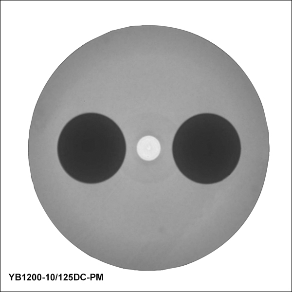
Figure 1.2 Yb-Doped PM Cladding-Pumped Fiber Cross Section
| Active Fibers Selection Guide | |||
|---|---|---|---|
| Ytterbium-Doped SM and LMA | Ytterbium-Doped PM | Erbium-Doped SM and LMA | Erbium-Doped PM |
Core-Pumped, Single-Clad SM PM Fiber
| Item # | YB300-6/125-PM |
|---|---|
| Cladding Geometry | Round, PANDA |
| Mode Field Diameter (MFD)a | 7.0 ± 0.5 µm |
| Peak Core Absorption @ 976 nmb | 300 dB/m |
| Core Diameterb | 5.5 µm |
| Cladding Diameter | 125 ± 2 µm |
| Coating Diameter | 245 ± 15 µm |
| Core Numerical Aperture (NA) | 0.12b |
| Core Backgroud Loss @ 1200 nm | ≤25 dB/km |
| Coating Material | Dual-Coated High-Index Acrylate |
| Cut-Off Wavelengthb | 860 ± 70 nm |
| Core Concentricity Error | ≤1.0 µm |
| Proof Test | ≥100 kpsi |
| Birefringence | ≥2.0 x 10⁻⁴ |
| Core Index | Proprietaryc |
| Cladding Index | Proprietaryc |
Cladding-Pumped, Double-Clad SM and LMA PM Fibers
| Item # | YB1200-6/125DC-PM | YB1200-10/125DC-PM | YB800-20/125DC-PM | YB1200-25/250DC-PM |
|---|---|---|---|---|
| Cladding Geometry | Round, PANDA | |||
| Mode Field Diameter (MFD) | 7.0 ± 0.5 μma | - | 15.0 ± 1.0 μma | - |
| Peak Cladding Absorption @ 976 nmb |
2.4 dB/m | 7.4 dB/m | 21.9 dB/m | 9.9 dB/m |
| Cladding Absorption @ 920 nm | 0.55 ± 0.1 dB/m | 1.7 ± 0.3 dB/m | 5.1 ± 0.75 dB/m | 2.3 ± 0.3 dB/m |
| Core Diameter | - | 10.0 ± 1.0 µm | 20.0 ± 1.5 µm | 25.0 ± 1.5 µm |
| Cladding Diameter | 125 ± 1 μm | 125 ± 1 μm | 125 ± 1.0 µm | 250 ± 6 μm |
| Coating (Second Cladding) Diameter | 245 ± 15 μm | 245 ± 15 μm | 245 ± 15 µm | 350 ± 15 μm |
| Core Numerical Aperture (NA) | 0.12b | 0.080 ± 0.005 | 0.065 ± 0.004 | 0.062 ± 0.005 |
| Cladding NA | - | ≥0.48 | ≥0.48 | ≥0.48 |
| Core Background Loss @ 1200 nm | ≤25 dB/km | |||
| Coating Material | Dual-Coated Low-Index Acrylate | |||
| Core Concentricity Error | ≤1.0 μm | |||
| Proof Test | ≥100 kpsi | |||
| Birefringence | ≥2.0 x 10⁻⁴ | ≥1.4 x 10⁻⁴ | ≥0.8 x 10⁻⁴ | ≥1.6 x 10⁻⁴ |
| Core Index | Proprietaryc | |||
| Cladding Index | Proprietaryc | |||
Matched Passive SM and LMA Fibers
| Item # | P-6/125DC-PM | P-10/125DC-PM | P-20/125DC-PM | P-25/250DC-PM |
|---|---|---|---|---|
| Matching Active Fiber | YB1200-6/125DC-PM | YB1200-10/125DC-PM | YB800-20/125DC-PM | YB1200-25/250DC-PM |
| Cladding Geometry | Round, Panda | |||
| Mode Field Diameter (MFD) | 7.0 ± 0.5 µma | - | 15.0 ± 1.0 µm | - |
| Core Diameter | - | 10.0 ± 1 µm | - | 25.0 ± 1.5 µm |
| Cladding Diameter | 125 ± 2 μm | 125.0 ± 1 μm | 125.0 ± 1 µm | 250 ± 3 µm |
| Coating (Second Cladding) Diameter | 245 ± 15 μm | 245 ± 15 μm | 245 ± 1 µm | 350 ± 15 µm |
| Core Numerical Aperture (NA) | 0.12b | 0.08 ± 0.005 | - | 0.070 ± 0.005 |
| Cladding NA | ≥0.48 | |||
| Core Background Loss @ 1200 nm | ≤5.0 dB/km | ≤15 dB/km | ≤5.0 dB/km | |
| Coating Material | Dual-Coated Low-Index Acrylate | |||
| Core Concentricity Error | ≤1.0 μm | |||
| Proof Test | ≥100 kpsi | |||
| Birefringence | ≥2.0 x 10⁻⁴ | ≥1.4 x 10⁻⁴ | ≥0.8 x 10⁻⁴ | ≥1.6 x 10⁻⁴ |
| Core Index | Proprietaryc | |||
| Cladding Index | Proprietaryc | |||
Active Optical Fiber Publications and Further Reading
As an emerging field of research, many advancements in doped fiber laser and amplifier construction are being made. The following publications contain information that may be helpful in the construction of fiber lasers and amplifiers.
2022
D. Stachowiak, M. Marzejon, J. Boguslawski, Z. Laszczych, K. Komar, M. Wojtkowski, and G. Sobon, "Femtosecond Er-doped fiber laser source tunable from 872 to 1075 nm for two-photon vision studies in humans," Biomed. Opt. Express 13, 1899-1911 (2022)
H. Ahmad, N.H. Mansor, S.A. Reduan, and R. Ramli, "Generation of mode-locked pulses based on D-shaped fiber with CdTe as a saturable absorber in the C-band region," RSC Adv. 12 (14), 8637-8646 (2022)
2021
Z. Laszczych and G. Sobon, "Dispersion management of a nonlinear amplifying loop mirror-based erbium-doped fiber laser," Opt. Express 29, 2690-2702 (2021)
G. Xie, Y. Liu, L. Zhou, Z. Zhu, Z. Deng, D. Luo, C. Gu, and W. Li, "Self-referenced frequency comb from a polarization-maintaining Er: Fiber laser based nonlinear polarization evolution," Results Phys. 22, 103886 (2021)
J. Zheng, S. Yang, X. Nie, and L. Li, "All-Polarization-Maintaining Passively Mode-Locked Erbium-Doped Fiber Laser Based on a WDM-Isolator-Tap Hybrid Device," J. Russ. Laser Res. 42, 82-86 (2021)
E.K. Ng, K.Y. Lau, H.K. Lee, N. Mohd Yusoff, A.R. Sarmani, M.F. Omar, and M.A. Mahdi, "L-band femtosecond fiber laser based on a reduced graphene oxide polymer composite saturable absorber," Opt. Mater. Express 11, 59-72 (2021)
2019
S. Li, Y. Yin, G. Ran, Q. Ouyang, Y. Chen, M. Tokurakawa, E. Lewis, S.W. Harun, and P. Wang, "Dual-wavelength mode-locked erbium-doped fiber laser based on tin disulfide thin film as saturable absorber," J. Appl. Phys. 125, 243104 (2019)
2018
M. Chernysheva, M.A. Araimi, G.A. Rance, N.J. Weston, B. Shi, S. Saied, J.L. Sullivan, N. Marsh, and A. Rozhin, "Revealing the nature of morphological changes in carbon nanotube-polymer saturable absorber under high-power laser irradiation," Sci. Rep. 8, 7491 (2018)
L.G. Holmen, G. Rustad, and M.W. Haakestad, "Eye-safe fiber laser for long-range 3D imaging applications," Appl. Opt. 57, 6760-6767 (2018)
2016
R. Sun, D. Jin, F. Tan, S. Wei, C. Hong, J. Xu, J. Liu, and P. Wang, "High-power all-fiber femtosecond chirped pulse amplification based on dispersive wave and chirped-volume Bragg grating," Opt. Express 24, 22806-22812 (2016)
2015
L.C. Sinclair, J.-D. Deschênes, L. Sonderhouse, W.C. Swann, I.H. Khader, E. Baumann, N.R. Newbury, and I. Coddington, "Invited Article: A compact optically coherent fiber frequency comb," Rev. Sci. Instrum. 86, 081301 (2015)
C. Kim, D. Kim, Y. Cheong, D. Kwon, S.Y. Choi, H. Jeong, S.J. Cha, J.-W. Lee, D.-I. Yeom, F. Rotermund, and J. Kim, "300-MHz-repetition-rate, all-fiber, femtosecond laser mode-locked by planar lightwave circuit-based saturable absorber," Opt. Express 23, 26234-26242 (2015)
2014
H. Kawagoe, S. Ishida, M. Aramaki, Y. Sakakibara, E. Omoda, H. Kataura, and N. Nishizawa, "Development of a high power supercontinuum source in the 1.7 μm wavelength region for highly penetrative ultrahigh-resolution optical coherence tomography," Biomed. Opt. Express 5, 932-943 (2014)
X. Li, W. Zou, and J. Chen, "41.9 fs hybridly mode-locked Er-doped fiber laser at 212 MHz repetition rate," Opt. Lett. 39, 1553-1556 (2014)
2013
N.A. Koliada, B.N. Nyushkov, A.V. Ivanenko, S.M. Kobtsev, P. Harper, S.K. Turitsyn, V.I. Denisov, and V.S. Pivtsov, "Generation of dissipative solitons in an actively mode-locked ultralong fibre laser," Quantum Electron. 43, 95 (2013)
2012
B. Samson, G. Oulundsen, A. Carter, and S. R. Bowman, "OPTICAL FIBER FABRICATION: Holmium-doped silica fiber designs extend fiber lasers beyond 2 µm," Laser Focus World, August 1, 2012
2011
J. Ding, B. Samson, A. Carter, C. Wang, and K. Tankala, "A Monolithic Thulium Doped Single Mode Fiber Laser with 1.5ns Pulsewidth and 8kW Peak Power," Proc. SPIE 7914, Fiber Lasers VIII: Technology, Systems, and Applications, 79140X (2011); doi:10.1117/12.876867
2010
T.S. McComb, P. Kadwani, R.A. Sims, L. Shah, C.C.C. Willis, G. Frith, V. Sudesh, B. Samson, and M. Richardson, "Amplification of Picosecond Pulses Generated in a Carbon Nanotube Modelocked Thulium Fiber Laser," in Lasers, Sources and Related Photonic Devices, OSA Technical Digest Series (CD) (Optical Society of America, 2010), paper AMB10; doi:10.1364/ASSP.2010.AMB10
G. Frith, A. Carter, B. Samson, J. Faroni, K. Farley, K. Tankala, and G.E. Town, "Mitigation of photodegradation in 790nm-pumped Tm-doped fibers," Proc. SPIE 7580, Fiber Lasers VII: Technology, Systems, and Applications, 75800A (2010); doi:10.1117/12.846230
2009
G. Frith, A. Carter, B. Samson, and G. Town, "Design considerations for short-wavelength operation of 790-nm-pumped Tm-doped fibers," Appl. Opt. 48, 5072-5075 (2009); doi:10.1364/AO.48.005072
S.D. Jackson, "The spectroscopic and energy transfer characteristics of the rare earth ions used fr silicate glass fibre lasers operating in the shortwave infrared," Laser Photonics Rev., 3, 466–482 (2009)
P. F. Moulton, G. A. Rines, E. V. Slobodtchikov, K. F. Wall, G. Frith, B. Samson, and A. L.G. Carter, "Tm-Doped Fiber Lasers: Fundamentals and Power Scaling," IEEE J. Sel. Top. Quantum Electron., 15, 85-92 (2009)
2006
A. Hemming, S. Bennetts, N. Simakov , J. Haub, and A. Carter, "Development of resonantly cladding-pumped holmium-doped fibre lasers," Proc. SPIE 8237, Fiber Lasers IX: Technology, Systems, and Applications, 82371J (2012); doi:10.1117/12.909458
W. Torruellas, Y. Chen, B. McIntosh, J. Farroni, K. Tankala, S. Webster, D. Hagan, M. J. Soileau, M. Messerly, and J. Dawson, "High peak power Ytterbium doped fiber amplifiers," Proc. SPIE 6102, Fiber Lasers III: Technology, Systems, and Applications, 61020N (2006); doi:10.1117/12.646571
| Quick Links |
|---|
| Damage at the Air / Glass Interface |
| Intrinsic Damage Threshold |
| Preparation and Handling of Optical Fibers |
Laser-Induced Damage in Silica Optical Fibers
The following tutorial details damage mechanisms relevant to unterminated (bare) fiber, terminated optical fiber, and other fiber components from laser light sources. These mechanisms include damage that occurs at the air / glass interface (when free-space coupling or when using connectors) and in the optical fiber itself. A fiber component, such as a bare fiber, patch cable, or fused coupler, may have multiple potential avenues for damage (e.g., connectors, fiber end faces, and the device itself). The maximum power that a fiber can handle will always be limited by the lowest limit of any of these damage mechanisms.
While the damage threshold can be estimated using scaling relations and general rules, absolute damage thresholds in optical fibers are very application dependent and user specific. Users can use this guide to estimate a safe power level that minimizes the risk of damage. Following all appropriate preparation and handling guidelines, users should be able to operate a fiber component up to the specified maximum power level; if no maximum is specified for a component, users should abide by the "practical safe level" described below for safe operation of the component. Factors that can reduce power handling and cause damage to a fiber component include, but are not limited to, misalignment during fiber coupling, contamination of the fiber end face, or imperfections in the fiber itself. For further discussion about an optical fiber’s power handling abilities for a specific application, please contact Thorlabs’ Tech Support.
Damage at the Air / Glass Interface
There are several potential damage mechanisms that can occur at the air / glass interface. Light is incident on this interface when free-space coupling or when two fibers are mated using optical connectors. High-intensity light can damage the end face leading to reduced power handling and permanent damage to the fiber. For fibers terminated with optical connectors where the connectors are fixed to the fiber ends using epoxy, the heat generated by high-intensity light can burn the epoxy and leave residues on the fiber facet directly in the beam path.
| Table 36C Estimated Optical Power Densities on Air / Glass Interfacea | ||
|---|---|---|
| Type | Theoretical Damage Thresholdb | Practical Safe Levelc |
| CW (Average Power) |
~1 MW/cm2 | ~250 kW/cm2 |
| 10 ns Pulsed (Peak Power) |
~5 GW/cm2 | ~1 GW/cm2 |
Damage Mechanisms on the Bare Fiber End Face
Damage mechanisms on a fiber end face can be modeled similarly to bulk optics, and industry-standard damage thresholds for UV Fused Silica substrates can be applied to silica-based fiber. However, unlike bulk optics, the relevant surface areas and beam diameters involved at the air / glass interface of an optical fiber are very small, particularly for coupling into single mode (SM) fiber. therefore, for a given power density, the power incident on the fiber needs to be lower for a smaller beam diameter.
Table 36C lists two thresholds for optical power densities: a theoretical damage threshold and a "practical safe level". In general, the theoretical damage threshold represents the estimated maximum power density that can be incident on the fiber end face without risking damage with very good fiber end face and coupling conditions. The "practical safe level" power density represents minimal risk of fiber damage. Operating a fiber or component beyond the practical safe level is possible, but users must follow the appropriate handling instructions and verify performance at low powers prior to use.
Calculating the Effective Area for Single Mode Fibers
The effective area for single mode (SM) fiber is defined by the mode field diameter (MFD), which is the cross-sectional area through which light propagates in the fiber; this area includes the fiber core and also a portion of the cladding. To achieve good efficiency when coupling into a single mode fiber, the diameter of the input beam must match the MFD of the fiber.
As an example, SM400 single mode fiber has a mode field diameter (MFD) of ~Ø3 µm operating at 400 nm, while the MFD for SMF-28 Ultra single mode fiber operating at 1550 nm is Ø10.5 µm. The effective area for these fibers can be calculated as follows:
SM400 Fiber: Area = Pi x (MFD/2)2 = Pi x (1.5 µm)2 = 7.07 µm2 = 7.07 x 10⁻⁸ cm2
SMF-28 Ultra Fiber: Area = Pi x (MFD/2)2 = Pi x (5.25 µm)2 = 86.6 µm2 = 8.66 x 10⁻⁷ cm2
To estimate the power level that a fiber facet can handle, the power density is multiplied by the effective area. Please note that this calculation assumes a uniform intensity profile, but most laser beams exhibit a Gaussian-like shape within single mode fiber, resulting in a higher power density at the center of the beam compared to the edges. Therefore, these calculations will slightly overestimate the power corresponding to the damage threshold or the practical safe level. Using the estimated power densities assuming a CW light source, we can determine the corresponding power levels as:
SM400 Fiber: 7.07 x 10⁻⁸ cm2 x 1 MW/cm2 = 7.1 x 10⁻⁸ MW = 71 mW (Theoretical Damage Threshold)
7.07 x 10⁻⁸ cm2 x 250 kW/cm2 = 1.8 x 10⁻⁵ kW = 18 mW (Practical Safe Level)
SMF-28 Ultra Fiber: 8.66 x 10⁻⁷ cm2 x 1 MW/cm2 = 8.7 x 10⁻⁷ MW = 870 mW (Theoretical Damage Threshold)
8.66 x 10⁻⁷ cm2 x 250 kW/cm2 = 2.1 x 10⁻⁴ kW = 210 mW (Practical Safe Level)
Effective Area of Multimode Fibers
The effective area of a multimode (MM) fiber is defined by the core diameter, which is typically far larger than the MFD of an SM fiber. For optimal coupling, Thorlabs recommends focusing a beam to a spot roughly 70 - 80% of the core diameter. The larger effective area of MM fibers lowers the power density on the fiber end face, allowing higher optical powers (typically on the order of kilowatts) to be coupled into multimode fiber without damage.
Damage Mechanisms Related to Ferrule / Connector Termination
 Click to Enlarge
Figure 36D Plot showing approximate input power that can be incident on a single mode silica optical fiber with a termination. Each line shows the estimated power level due to a specific damage mechanism. The maximum power handling is limited by the lowest power level from all relevant damage mechanisms (indicated by a solid line).
Fibers terminated with optical connectors have additional power handling considerations. Fiber is typically terminated using epoxy to bond the fiber to a ceramic or steel ferrule. When light is coupled into the fiber through a connector, light that does not enter the core and propagate down the fiber is scattered into the outer layers of the fiber, into the ferrule, and the epoxy used to hold the fiber in the ferrule. If the light is intense enough, it can burn the epoxy, causing it to vaporize and deposit a residue on the face of the connector. This results in localized absorption sites on the fiber end face that reduce coupling efficiency and increase scattering, causing further damage.
For several reasons, epoxy-related damage is dependent on the wavelength. In general, light scatters more strongly at short wavelengths than at longer wavelengths. Misalignment when coupling is also more likely due to the small MFD of short-wavelength SM fiber that also produces more scattered light.
To minimize the risk of burning the epoxy, fiber connectors can be constructed to have an epoxy-free air gap between the optical fiber and ferrule near the fiber end face. Our high-power multimode fiber patch cables use connectors with this design feature.
Determining Power Handling with Multiple Damage Mechanisms
When fiber cables or components have multiple avenues for damage (e.g., fiber patch cables), the maximum power handling is always limited by the lowest damage threshold that is relevant to the fiber component. In general, this represents the highest input power that can be incident on the patch cable end face and not the coupled output power.
As an illustrative example, Figure 36D shows an estimate of the power handling limitations of a single mode fiber patch cable due to damage to the fiber end face and damage via an optical connector. The total input power handling of a terminated fiber at a given wavelength is limited by the lower of the two limitations at any given wavelength (indicated by the solid lines). A single mode fiber operating at around 488 nm is primarily limited by damage to the fiber end face (blue solid line), but fibers operating at 1550 nm are limited by damage to the optical connector (red solid line).
In the case of a multimode fiber, the effective mode area is defined by the core diameter, which is larger than the effective mode area for SM fiber. This results in a lower power density on the fiber end face and allows higher optical powers (on the order of kilowatts) to be coupled into the fiber without damage (not shown in graph). However, the damage limit of the ferrule / connector termination remains unchanged and as a result, the maximum power handling for a multimode fiber is limited by the ferrule and connector termination.
Please note that these are rough estimates of power levels where damage is very unlikely with proper handling and alignment procedures. It is worth noting that optical fibers are frequently used at power levels above those described here. However, these applications typically require expert users and testing at lower powers first to minimize risk of damage. Even still, optical fiber components should be considered a consumable lab supply if used at high power levels.
Intrinsic Damage Threshold
In addition to damage mechanisms at the air / glass interface, optical fibers also display power handling limitations due to damage mechanisms within the optical fiber itself. These limitations will affect all fiber components as they are intrinsic to the fiber itself. Two categories of damage within the fiber are damage from bend losses and damage from photodarkening.
Bend Losses
Bend losses occur when a fiber is bent to a point where light traveling in the core is incident on the core/cladding interface at an angle higher than the critical angle, making total internal reflection impossible. Under these circumstances, light escapes the fiber, often in a localized area. The light escaping the fiber typically has a high power density, which burns the fiber coating as well as any surrounding furcation tubing.
A special category of optical fiber, called double-clad fiber, can reduce the risk of bend-loss damage by allowing the fiber’s cladding (2nd layer) to also function as a waveguide in addition to the core. By making the critical angle of the cladding/coating interface higher than the critical angle of the core/clad interface, light that escapes the core is loosely confined within the cladding. It will then leak out over a distance of centimeters or meters instead of at one localized spot within the fiber, minimizing the risk of damage. Thorlabs manufactures and sells 0.22 NA double-clad multimode fiber, which boasts very high, megawatt range power handling.
Photodarkening
A second damage mechanism, called photodarkening or solarization, can occur in fibers used with ultraviolet or short-wavelength visible light, particularly those with germanium-doped cores. Fibers used at these wavelengths will experience increased attenuation over time. The mechanism that causes photodarkening is largely unknown, but several fiber designs have been developed to mitigate it. For example, fibers with a very low hydroxyl ion (OH) content have been found to resist photodarkening and using other dopants, such as fluorine, can also reduce photodarkening.
Even with the above strategies in place, all fibers eventually experience photodarkening when used with UV or short-wavelength light, and thus, fibers used at these wavelengths should be considered consumables.
Preparation and Handling of Optical Fibers
General Cleaning and Operation Guidelines
These general cleaning and operation guidelines are recommended for all fiber optic products. Users should still follow specific guidelines for an individual product as outlined in the support documentation or manual. Damage threshold calculations only apply when all appropriate cleaning and handling procedures are followed.
-
All light sources should be turned off prior to installing or integrating optical fibers (terminated or bare). This ensures that focused beams of light are not incident on fragile parts of the connector or fiber, which can possibly cause damage.
-
The power-handling capability of an optical fiber is directly linked to the quality of the fiber/connector end face. Always inspect the fiber end prior to connecting the fiber to an optical system. The fiber end face should be clean and clear of dirt and other contaminants that can cause scattering of coupled light. Bare fiber should be cleaved prior to use and users should inspect the fiber end to ensure a good quality cleave is achieved.
-
If an optical fiber is to be spliced into the optical system, users should first verify that the splice is of good quality at a low optical power prior to high-power use. Poor splice quality may increase light scattering at the splice interface, which can be a source of fiber damage.
-
Users should use low power when aligning the system and optimizing coupling; this minimizes exposure of other parts of the fiber (other than the core) to light. Damage from scattered light can occur if a high power beam is focused on the cladding, coating, or connector.
Tips for Using Fiber at Higher Optical Power
Optical fibers and fiber components should generally be operated within safe power level limits, but under ideal conditions (very good optical alignment and very clean optical end faces), the power handling of a fiber component may be increased. Users must verify the performance and stability of a fiber component within their system prior to increasing input or output power and follow all necessary safety and operation instructions. The tips below are useful suggestions when considering increasing optical power in an optical fiber or component.
-
Splicing a fiber component into a system using a fiber splicer can increase power handling as it minimizes possibility of air/fiber interface damage. Users should follow all appropriate guidelines to prepare and make a high-quality fiber splice. Poor splices can lead to scattering or regions of highly localized heat at the splice interface that can damage the fiber.
-
After connecting the fiber or component, the system should be tested and aligned using a light source at low power. The system power can be ramped up slowly to the desired output power while periodically verifying all components are properly aligned and that coupling efficiency is not changing with respect to optical launch power.
-
Bend losses that result from sharply bending a fiber can cause light to leak from the fiber in the stressed area. When operating at high power, the localized heating that can occur when a large amount of light escapes a small localized area (the stressed region) can damage the fiber. Avoid disturbing or accidently bending fibers during operation to minimize bend losses.
-
Users should always choose the appropriate optical fiber for a given application. For example, large-mode-area fibers are a good alternative to standard single mode fibers in high-power applications as they provide good beam quality with a larger MFD, decreasing the power density on the air/fiber interface.
-
Step-index silica single mode fibers are normally not used for ultraviolet light or high-peak-power pulsed applications due to the high spatial power densities associated with these applications.
| Posted Comments: | |
龙威 王
(posted 2025-07-13 20:41:55.573) 我想要这个光纤横截面发射谱和吸收谱的数据用于画图 EGies
(posted 2025-11-04 12:42:22.0) Thank you for contacting Thorlabs regarding the emission and absorption spectrum data for the YB300-6/125-PM fiber. We have a graph of the Ytterbium-Doped fiber absorption and emission cross sections available here: https://www.thorlabs.com/images/TabImages/Yb_fiber_cross_sections_800.gif jlow
(posted 2014-08-28 03:32:46.0) Response from Jeremy at Thorlabs: We typically only sell this by the meter. We might have some smaller pieces available though. I will check on this and contact you directly. Buki at Thorlabs
(posted 2011-01-27 02:38:16.0) Thank you for your feedback, Robin. There may have been a delay between when you clicked on the tab and when it loaded. The Documents and drawings tab worked fine when we tested it on both the .com and .hk sites. Please try again and contact TechSupport@thorlabs.com if youre still having problems accessing the files. rw
(posted 2011-01-26 12:05:35.0) Hi,
From this page:
http://www.thorlabs.hk/newgrouppage9.cfm?objectgroup_id=1785
there is a link to Documents and Drawings:
http://www.thorlabs.hk/1785Documents%20&%20Drawings
but your server reports there is no such page.
Cheers
- Robin |

 Zoom
Zoom- High Core Pump Absorption: 75 ± 10 dB/m @ 920 nm
- Good Spliceability to Standard Single Mode Fibers
- Extremely High Photodarkening Resistivity
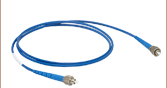
The Liekki YB300-6/125-PM ytterbium-doped single mode, single-clad fiber is ideal for low average power fiber laser and amplifier applications. This fiber offers high core pump absorption, extremely high photodarkening resistivity, and good spliceability to standard single mode fibers such as Thorlabs' PM980-XP or SM980-5.8-125 fibers. This ytterbium-doped fiber can be used as a core pumped pre-amplifier for a fiber amplifier chain or in infrared (IR) sources for frequency doubling. Matching passive fiber is sold below.
| Item #a | Cladding Geometry | Absorption @ 920 nm |
Core Diameter | MFDb | Cladding Diameter | Coating Diameter | Core NAc |
|---|---|---|---|---|---|---|---|
| YB300-6/125-PM | Round, PANDA | 75 ± 10 dB/m | 5.5 ± 1.0 µm | 7.0 ± 0.5 µm | 125 ± 2 µm | 245 ± 15 µm | 0.12 |

 Zoom
Zoom
Click to Enlarge
Figure G2.1 See Table G2.2 for Slope Efficiency Graphs for Other Fibers
Applications
- Low-Cost Marking Lasers
- High Average Power Pulsed Amplifiers
- Medium- and High-Power Pulsed and CW Lasers
- Materials Processing
- Laser Range Finding (LIDAR)
Features
- Cladding-Pumped Design
- Single Mode (SM) or Large-Mode-Area (LMA) Operation
- High Pump Absorption with Low Photodarkening
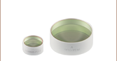
These Yb-doped double-clad fibers are ideal for medium- and high-power applications up to 20 W including fiber power amplifiers in pulsed operation. Matching passive fibers are sold below.
| Key Features | |
|---|---|
| YB1200-6/125DC-PM | Telecom-like geometry for compatibility with standard components such as gratings and combiners. |
| YB1200-10/125DC-PM | High cladding absorption and a single mode core are ideal for fiber-based power amplifiers. |
| YB800-20/125DC-PM | High cladding absorption is ideal for short-pulse applications requiring a large core-cladding ratio. |
| YB1200-25/250DC-PM | High cladding absorption and high efficiency for high average power pulsed fiber amplifiers. |
| Table G2.2 Specifications | |||||||||
|---|---|---|---|---|---|---|---|---|---|
| Item #a | Cladding Geometry |
Absorption @ 920 nm |
Core Diameter | MFD | Cladding Diameter |
Coating (Second Cladding) Diameter |
Core NA |
Cladding NA |
Slope Efficiency Plot |
| YB1200-6/125DC-PM | Round, PANDA | 0.55 ± 0.1 dB/m | - | 7.0 ± 0.5 µmb | 125 ± 1 µm | 245 ± 15 µm | 0.12c | - |  |
| YB1200-10/125DC-PM | 1.7 ± 0.3 dB/m | 10.0 ± 1.0 µm | - | 0.080 ± 0.005 | ≥0.48 |  |
|||
| YB800-20/125DC-PM | 5.1 ± 0.75 dB/m | 20.0 ± 1.5 µm | 15.0 ± 1.0 µmb | 125 ± 1.0 µm | 0.065 ± 0.004 | - | |||
| YB1200-25/250DC-PM | 2.3 ± 0.3 dB/m | 25.0 ± 1.5 µm | - | 250 ± 6 µm | 350 ± 15 µm | 0.062 ± 0.005 | |
||

 Zoom
Zoom- Optimized for Coupling to Active Doped Fibers
- Single Mode and Large Mode Area (LMA) Options
- Industry-Standard Geometries for Easy Handling
- Polarization Maintaining
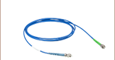
These passive PM fibers are mode-matched with the YB300-6/125-PM single-clad active fiber and the YB1200-6/125DC-PM, YB1200-10/125DC-PM, YB800-20/125DC-PM, and YB1200-25/250DC-PM double-clad active fibers sold above (see Table G3.1). The core diameter and numerical aperture of each fiber is chosen to match that of its active counterpart to maintain excellent beam quality throughout fiber laser or amplifier systems.
These passive fibers are coated with low-index acrylate for pumping active fibers. High-index acrylate-coated fibers are available by special request; please contact Tech Support for details.
| Table G3.1 Specifications | |||||||||
|---|---|---|---|---|---|---|---|---|---|
| Item #a | Compatible Active Fiber |
Cladding Geometry |
Core Diameter |
MFD | Cladding Diameter |
Coating (Second Cladding) Diameter |
Core NA |
Cladding NA | Proof Test |
| P-6/125DC-PM | YB300-6/125-PM YB1200-6/125DC-PM |
Round, Panda |
- | 7.0 ± 0.5 µmb | 125 ± 2 µm | 245 ± 15 µm | 0.12 (Nominal) |
≥0.48 | ≥100 kpsi |
| P-10/125DC-PM | YB1200-10/125DC-PM | 10.0 ± 1 µm | - | 125.0 ± 1 µm | 0.08 ± 0.005 | ||||
| P-20/125DC-PM | YB800-20/125DC-PM | - | 15.0 ± 1.0 µmb | 125.0 ± 1 µm | - | ||||
| P-25/250DC-PM | YB1200-25/250DC-PM | 25.0 ± 1.5 µm | - | 250 ± 3 µm | 350 ± 15 µm | 0.070 ± 0.005 | |||