 Products Home / Optomechanical Components / Optical Post Assemblies / Mini-Series Optical Post Assemblies / Mini-Series Slotted Bases
Mini-Series Slotted Bases
- Compatible with Mini-Series Posts
- Available with Imperial or Metric Footprint
- Bottom Relief Cuts Ensure Stable Mounting
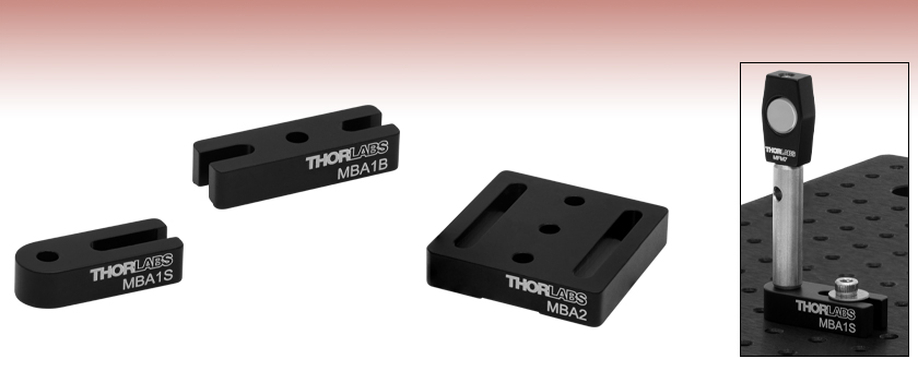
MBA1S
Mini-Series Mounting Base,
0.39" x 1.00" x 0.25"
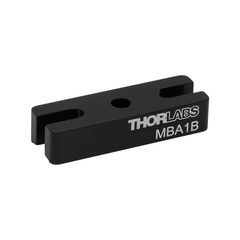
MBA1B
Mini-Series Mounting Base,
0.39" x 1.18" x 0.25"
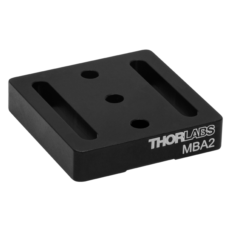
MBA2
Mini-Series Mounting Base,
1.18" x 1.18" x 0.25"
Application Image
Mini-Series Assembly Mounted on a MBY6 Breadboard


Please Wait
Features
- Compatible with Mini-Series Imperial and Metric Breadboards and Posts
- Attach to Posts via Bottom-Located #4 (M3) Counterbored Mounting Hole(s)
- Mount on Breadboard or Optical Table via Clearance Slot(s) for #4 (M3) Cap Screws
- Fabricated from Black Anodized Aluminum with Bottom Relief Cuts for Stable Mounting
Thorlabs offers a variety of Mini-Series anodized aluminum bases to mount Mini-Series components in a compact assembly. For close positioning of components, our MBA1S(/M) base features the smallest footprint of 0.39" x 1.00" x 0.25" (9.5 mm x 25.0 mm x 6.0 mm). For increased stability while maintaining a small footprint of 0.39" x 1.18" x 0.25" (9.5 mm x 29.5 mm x 6.0 mm), the two-slotted MBA1B(/M) is a good option. For the greatest stability, consider our MBA2(/M) base, which offers the largest contact area of 1.18" x 1.18" x 0.25" (29.5 mm x 29.5 mm x 6.0 mm), and features two straight slots.
Please note that a 0.25" long, 4-40 (6 mm long, M3) cap screw (Item #s SH4S050 and SH3M12, respectively) is recommended for attaching Mini-Series posts to these mounting bases.
| Item # | MBA1S(/M) | MBA1B(/M) | MBA2(/M) |
|---|---|---|---|
| Click Image to Enlarge | 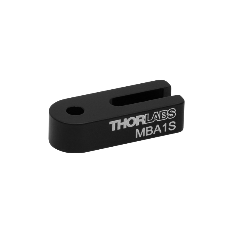 |
 |
 |
| Slots | 1 | 2 | 2 |
| Slot Type | Straight | Straight | Straighta |
| Slot Length | 0.47" (12.0 mm) | 0.25" (6.5 mm) | 0.80" (20.0 mm) |
| Mounting Holes | 1 | 1 | 3 |
| Dimensions (W x L x H) |
0.39" x 1.00" x 0.25" (9.5 mm x 25.0 mm x 6.0 mm) |
0.39" x 1.18" x 0.25" (9.5 mm x 29.5 mm x 6.0 mm) |
1.18" x 1.18" x 0.25" (29.5 mm x 29.5 mm x 6.0 mm) |
| Image (Click to Enlarge) |
Description |
|---|---|
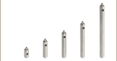
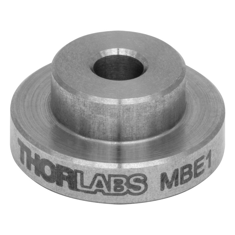 MBE1 |
Base Adapter for Mini-Series Posts The MBE1 Pedestal Base Adapter features a #4 (M3) counterbore for compatibility with the bottom of our Mini-Series posts to convert them into pedestal-style mounts. Made from solid 303 stainless steel with a 0.56" (14.2 mm) outer diameter, this adapter allows these posts to be used with our MSC1, MSC3, and MSC2 clamping forks. |
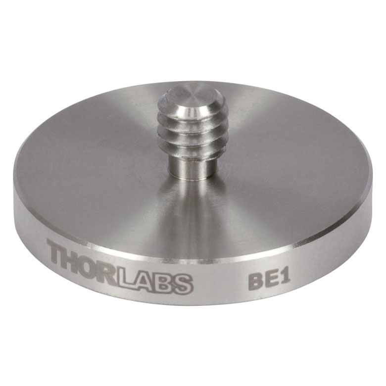 BE1 |
Base Adapter for Ø1/2" Post Holders and Ø1" Posts The BE1 Pedestal Base Adapter features a 1/4"-20 (M6)-threaded stud which fits into the bottom of our standard Ø1/2" post holders or Ø1" post extensions to convert them into pedestal-style mounts. Made from solid 303 stainless steel with a 1.25" (31.8 mm) outer diameter, this adapter allows these posts to be used with our CF125 and CF175 clamping forks. |
 RS05PC |
Ø1" Ceramic Pedestal Pillar Post The RS05PC Ceramic Pedestal Post is designed to provide high levels of thermal and electrical isolation. It is ideal for mounting components that may be sensitive to heat or sources of electrical noise. This adapter is compatible with our CF125 and CF175 clamping forks. |
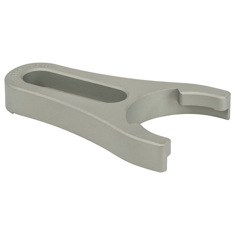
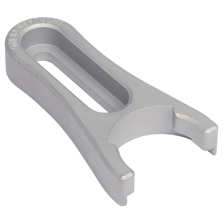 CF125 |
Small Clamping Fork The CF125 Clamping Fork was designed with positional flexibility in mind. This clamping fork is directly compatible with our Pedestal Style Post Holders and RSP-Series Ø1" Pedestal Pillar Posts. The solid steel construction, complete with carefully placed relief cuts and landing pads, provides exceptional clamping stability. The counterbored slot is 1.25" (32 mm) in length, is designed to accept a 1/4"-20 (M6) cap screw and washer, and allows the clamp to swivel about the pedestal base in order to align with the most convenient mounting holes. |
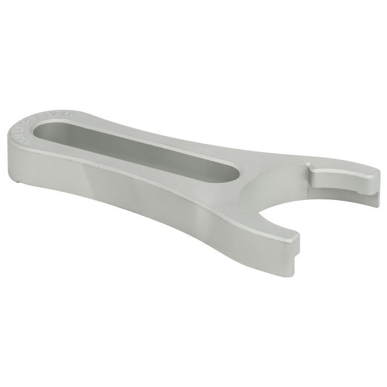
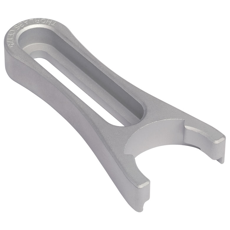 CF175 |
Large Clamping Fork The CF175 Clamping Fork was designed with positional flexibility in mind. This clamping fork is directly compatible with our Pedestal Style Post Holders and RSP-Series Ø1" Pedestal Pillar Posts. The solid steel construction, complete with carefully placed relief cuts and landing pads, provides exceptional clamping stability. The counterbored slot is 1.75" (44.4 mm) in length, is designed to accept a 1/4"-20 (M6) cap screw and washer, and allows the clamp to swivel about the pedestal base in order to align with the most convenient mounting holes. |
 POLARIS-CA1 |
Polaris™ Non-Bridging Clamping Arm The Polaris Clamping Arm is the ideal solution for stably mounting any Ø1" post. Each clamping arm, which is constructed from heat-treated, stress-relieved 303 stainless steel, provides extremely high holding forces with minimal torquing of the mounting screws. The side-located clamping mechanism is actuated using a 1/4"-20 cap screw. Because the side-located clamp and mounting slot are tightened separately, the user can set the position of the fork and adjust the rotational alignment independently. The clamping arm has a compact 3.33" x 1.60" (84.5 mm x 40.6 mm) footprint for tight laser cavity setups, with a thickness of 0.60" (15.2 mm) for increased stability. A 1.30" (33.0 mm) long clearance slot allows for a variety of mounting solutions using a 1/4"-20 or M6 cap screw and washer. This clamping arm is also avaiable with a metric cap screw (POLARIS-CA1/M). |
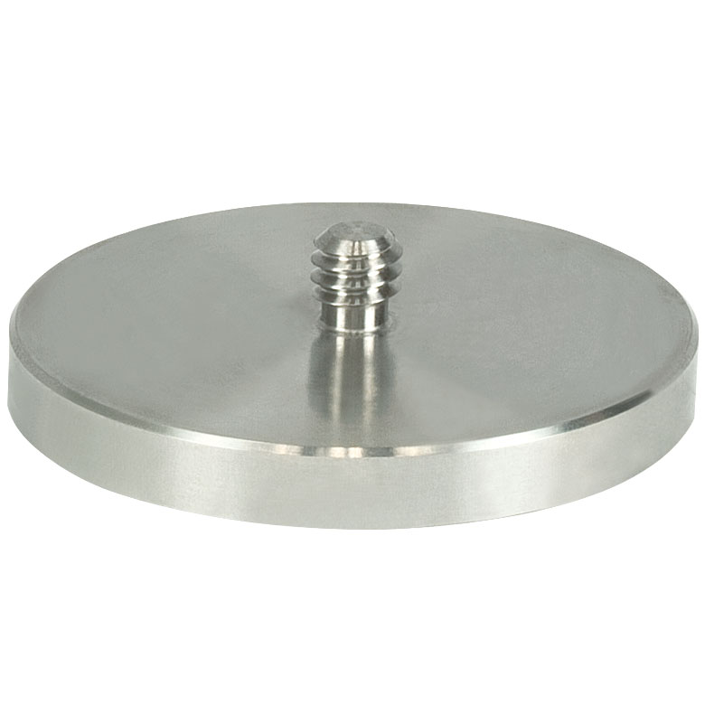 PB4 |
Base Adapter for Ø1" Post Holders and Ø1.5" Posts The PB4 pedestal base adapter features a 1/4"-20 (M6)-threaded stud which fits into the bottom of our Ø1.5" posts to convert them into pedestal-style mounts. Made from solid 303 stainless steel with a 1.85" (47.0 mm) outer diameter, this adapter allows these posts to be used with our PF85B, PF125B, or PF175 clamping forks. |
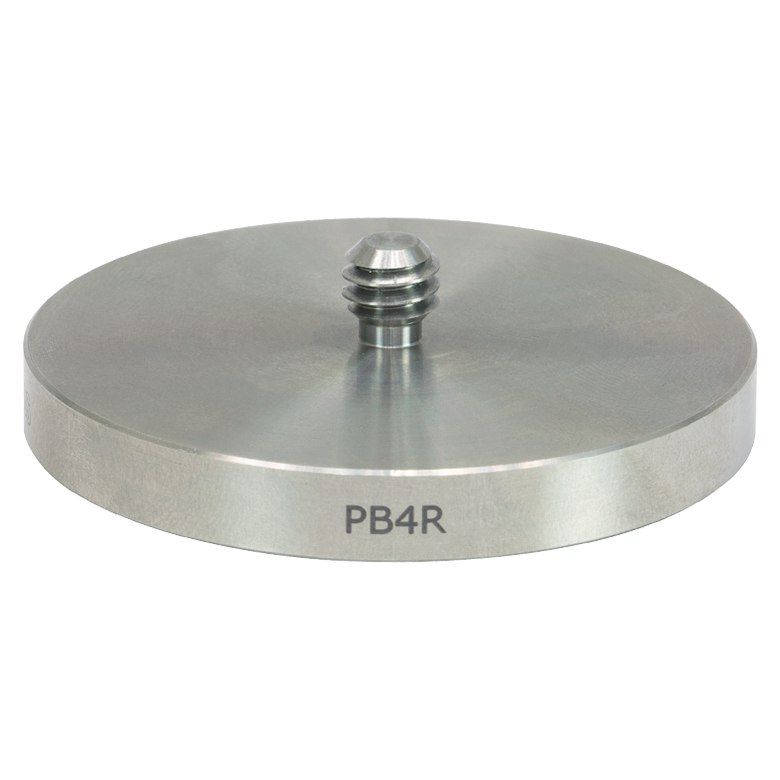 PB4R |
Magnetic Base Adapter for Ø1" Post Holders and Ø1.5" Posts The PB4R pedestal base adapter features a 1/4"-20 (M6)-threaded stud which fits into the bottom of our Ø1.5" posts to convert them into pedestal-style mounts. Made from solid 303 stainless steel with a 1.85" (47.0 mm) outer diameter, this adapter allows these posts to be used with our PF85B, PF125B, or PF175 clamping fork. There are four high strength magnets in the base that are sufficiently strong to securely hold the base in place on an optical table. |
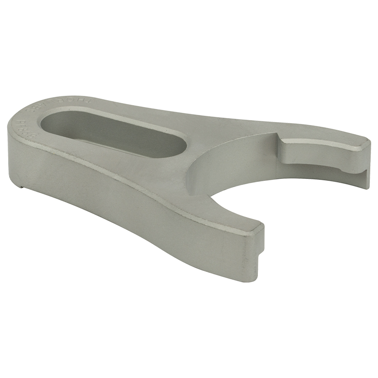 PF85B |
Compact P-Series Clamping Fork The PF85B is specifically designed to secure our Ø1" Post Holders or our PB4 pedestal base adapters. It has a 0.85" (21.6 mm) long counterbored slot that is designed to accept a 1/4"-20 (M6) cap screw and washer. The clamp can swivel about the pedestal base in order to align with the most convenient mounting holes. |
 PF125B |
Small P-Series Clamping Fork The PF125B is specifically designed to secure our Ø1" Post Holders or our PB4 pedestal base adapters. It has a 1.25" (31.8 mm) long counterbored slot that is designed to accept a 1/4"-20 (M6) cap screw and washer. The clamp can swivel about the pedestal base in order to align with the most convenient mounting holes. |
 PF175B |
Large P-Series Clamping Fork The PF175B is specifically designed to secure our Ø1" Post Holders or our PB4 pedestal base adapters. It has a 2.12" (53.8 mm) long counterbored slot that is designed to accept a 1/4"-20 (M6) cap screw and washer. The clamp can swivel about the pedestal base in order to align with the most convenient mounting holes. |
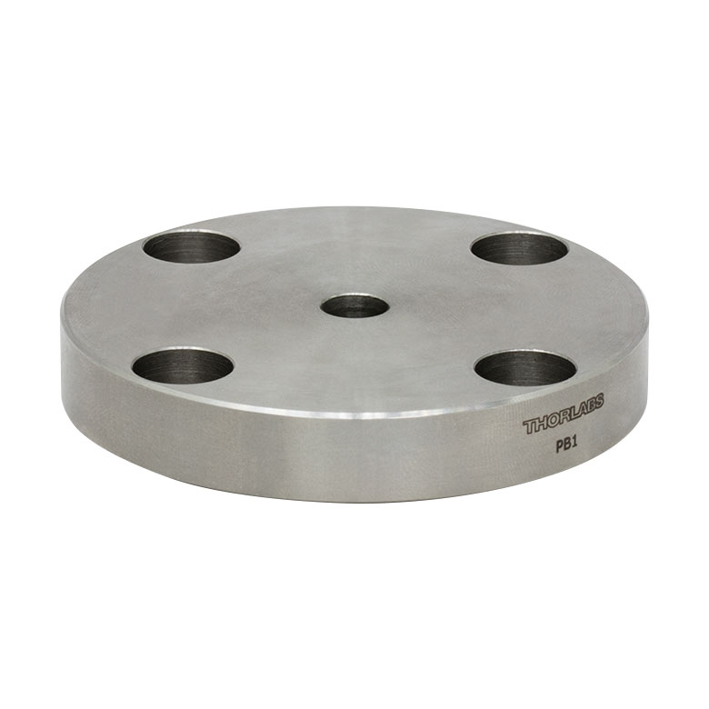 PB1 |
Mounting Post Base for Ø1.5" Posts This standard Ø2.48" post base bolts directly onto P-Series posts and adds 0.40" to the height of the post. To mount directly onto an optical bench, four 1/4 (M6) counterbored holes on 2" (50 mm) centers are provided. |
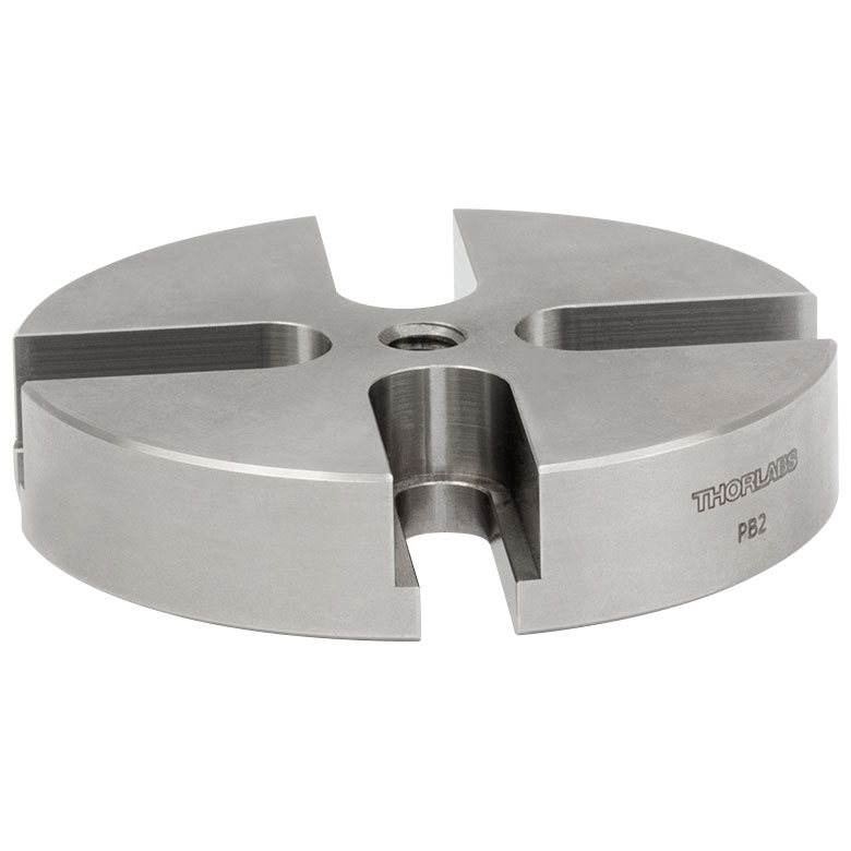 PB2 |
Slotted Mounting Post Base for Ø1.5" Posts This universal Ø2.40" post base allows random placement of a P-Series post on an optical bench. The PB2 attaches to the P-Series posts using the 1/4"-20 (M6) center-tapped hole and adds 0.50" to the height of the post. |
 KB1X1 |
1" x 1" Kinematic Base This kinematic base consists of two plates: a top mounting plate and a bottom base plate. The two plates measure 1" (25 mm) to a side and are magnetically coupled using two pairs of high strength magnets. The top plate can be removed and replaced, automatically repositioning to an exact location with the repeatability of one microradian. The bottom plate can be fastened using a center-located #8 (M4) counterbore. Both the top (Item# KBT1X1) and bottom (Item# KBB1X1) plates can be purchased separately. |
 KB3X3 |
3" x 3" Kinematic Base This kinematic base consists of two plates: a top mounting plate and a bottom base plate. The two plates measure 3" (75 mm) to a side and are magnetically coupled using two pairs of high strength magnets. The bottom plate can be fastened to an optical bench using two 1/4"-20 (M6) clearance slots. These mounting slots can be accessed with the top plate in place. Both the top (Item# KBT3X3) and bottom (Item# KBB3X3) plates can be purchased separately. |
 KBM1 |
Lockable Kinematic Breaboard (3.94" x 3.94") This kinematic base consists of two plates: a top mounting plate and a bottom base plate. The two plates measure 3.94" (100 mm) to a side and are magnetically coupled using two pairs of high strength magnets. With a ball and V-groove design, the top plate can be removed and replaced with a lateral repeatability of 30 µm. The high repeatability of the unit allows minimal readjustment of the setup for applications where frequent removal and insertion of components is needed. The top plate has an array of 39 1/4"-20 (M6) tapped holes [0.46" (11.8 mm) deep] spaced 0.5" (12.5 mm) apart and provides the same mounting functionality as an optical breadboard. The bottom plate has two 2.00" (50.0 mm) long counterbored slots for 1/4"-20 (M6) cap screws for mounting to an optical table. |
 RB2 |
Adjustable Height Post Base The RB2 has a 0.90" (23 mm) deep base, which allows for maximum height adjustment of the RS Series of pillar posts. The locking screw is located on the top surface of the base, allowing for convenient vertical access. |
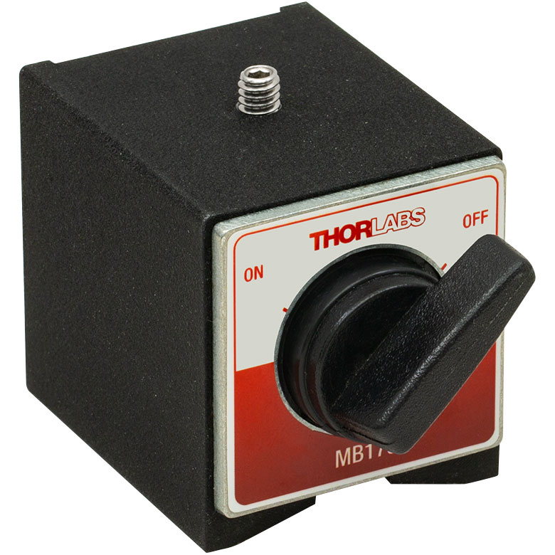 MB175 |
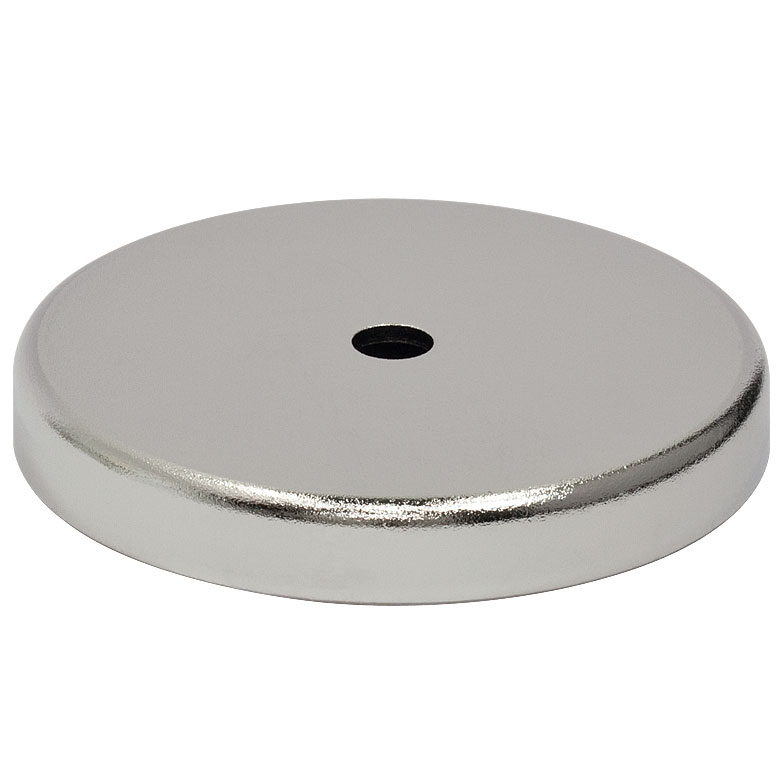
Magnetic Base For use with our standard Ø1/2" stainless steel post or our Ø1" post holders, this heavy-duty magnetic base has a switchable magnet for quick positioning of optical components. It provides 175 pounds of holding force. The two bottom mounting surfaces have been precision ground for optical bench applications. |
 IB3 |
Instrument Base The IB3 precision-machined aluminum instrument base provides flat, stable mounting and is useful for maneuvering items such as a post-mounted power meter head into and out of the beam path. |
 PMB3 |
Permanent Magnetic Base The PMB3 combines the convenience of our IB3 Base (above) with the benefit of a powerful magnet. The magnet is sufficiently strong to hold the base in place securely without needing to clamp it to an optical table. These bases are ideal for semi-permanent placement of an instrument or optical head. |
 SB1 |
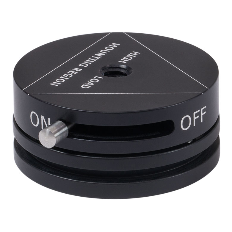
Switchable Kinematic Base This compact kinematic base is designed to allow easy removal and exact repositioning of the top plate. An On/Off switch controls the magnetic force that firmly holds the two plates together. Additional top (Item# SB1T) and bottom (Item# SB1B) plates can be purchased separately. |
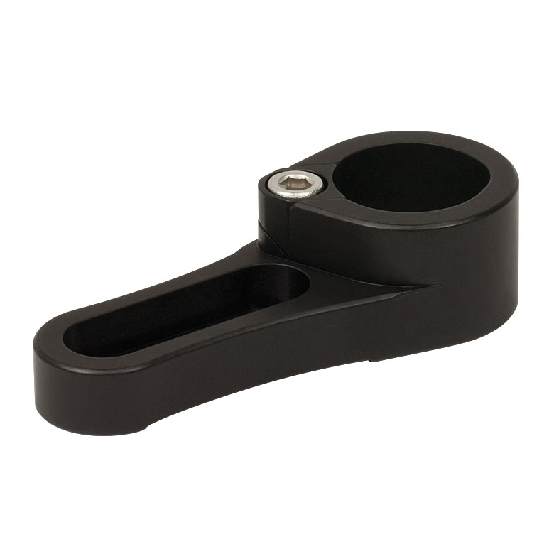
 NX1NF |
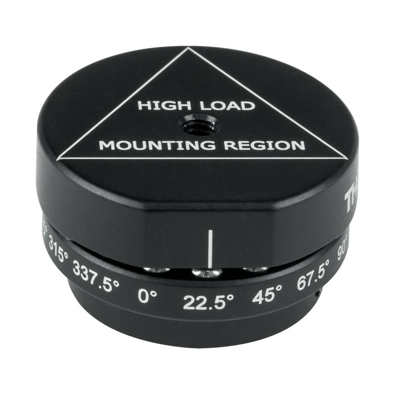
Indexing Mounting Base This base is ideal for redirecting a laser to multiple targets on your optical table. Applications include precise switching of shared laser systems, directing optical signals to multiple test instruments, and easy exchange of optical components (with extra top mounts). For best performance, ensure that the NX1NF is securely attached to its support structure. A series of three #8-32 (M4-0.7) tapped mounting holes are provided for mounting the bottom plate to a post or breadboard and the top plate has a single 8-32 tap for mounting optical components. |
 NX1F ESK01 |
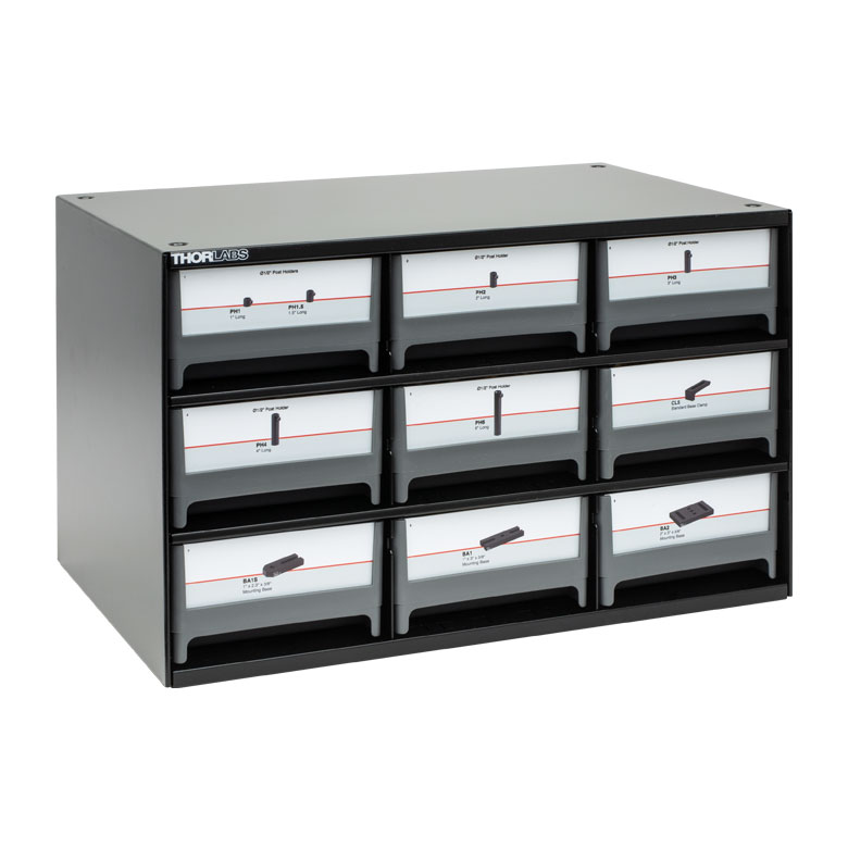
Bases and Post Holders Essentials Kit For those who are just starting out and need a little bit of everything, the ESK01 Bases and Post Holders Essentials Kit contains 130 of the most commonly used post holders, bases, and table clamps, all conveniently housed in a completely labeled cabinet. The large variety of sizes provides the maximum amount of flexibility when breadboarding an optical system. This kit is best used in conjunction with ESK03 Post and Accessories Essentials Kit. |

Insights into Best Lab Practices
Scroll down to read about a few things we consider when setting up lab equipment.
- Washers: Using Them with Optomech
- Bases: For Stability Orient the Side with the Undercut Down
Click here for more insights into lab practices and equipment.
Washers: Using Them with Optomech
Click to Enlarge
Figure 174B Install washers before inserting bolts into slots to protect the slot from damage. The rounded, smooth side of the washer should be placed against the slot, and the rough, flat side should be in contact with the bolt head. The smooth surface is designed to translate easily across the anodized surface, without harming it. The BA2 base is illustrated.
Click to Enlarge
Figure 174A The diameter of the washer is 35% larger than that of the bolt head. This results in over a six fold increase in overlap area with the slot of a BA2 base. By distributing the force of the bolt over a larger area, the washer help prevent gouging of the slot.
The head of a standard cap screw is not much larger than the major diameter of the thread (Figure 174A). For example, a 1/4"-20 screw has a head diameter between 0.365" and 0.375" and the clearance hole diameter for the threads is 0.264".
When the screw is tightened directly through the clearance hole to secure the device, the force is applied to the edge of the through hole, often cutting into the material (Figure 174A).
Once the material is permanently deformed, the screw head will want to fall back into the gouged groove, thereby moving the device back to that location when attempting to make fine adjustments.
A device with a circular through hole is not meant to translate around the screw thread so the deformation is not expected to be a problem.
However, a slot should provide the ability to secure the device anywhere along the length for the lifetime of the part. Using a washer distributes the force away from the slot edge to decrease the chance of deforming the slot and extending the lifetime of the part. Figure 174A illustrates the difference a washer can make. The contact area between the slot of a BA2 base and a 0.27" diameter cap screw is 0.010 in2. When a 0.5" diameter washer is used the contact area is 0.064 in2, which is over six times larger.
When using a Thorlabs washer, there are two distinct sides (Figure 174B). One side is flat and rough and the other is curved and polished. The curved and polished side should be placed against the device, which has an anodized surface.
As the screw tightens, the screw head can force the washer to spin against the anodized coating.
If the flat side is pressed down against the anodization, the friction created by the rough flat side can scratch the anodized aluminum. However, if the curved side is facing down, the smooth surface has less friction leading to less scratches and extending the visual appearance of the device.
Date of Last Edit: Dec. 4, 2019
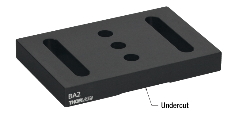
Bases: For Stability Orient the Side with the Undercut Down
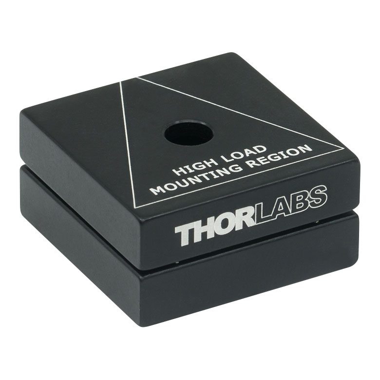
An undercut is machined into the bottom surface of bases like the BA2 (Figures 174C and 174D). The undercut creates feet, which are called pads. For maximum stability, the base should be oriented with its pads in contact with the table or breadboard.
The top surface of the base does not have an undercut and is the intended mounting surface for components.
Mounting the base upside down could result in the base rocking on the table or breadboard, or the base may exhibit other mechanical instability.
The Pads are Flatter than the Top Surface
The undercut is key to the flatness of the pads. The pads are machined flat after the undercut is made.
Friction heats the pads during the processing step that provides them with a maximally flat profile. By reducing the surface area of the pads, the undercut reduces the amount of heat generated during this step.
It is beneficial to minimize the heat generated during machining. Metal expands when heated, and the uneven heating that occurs during machining can distort the dimensions of the part. If the dimensions of the part are distorted during machining, the part can be left with high spots and other undesirable features after it cools. This can cause instability and misalignment when using the part.
Precision Instruments and Devices have Pads
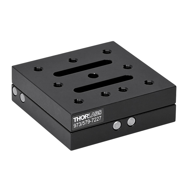
Another example of a component with pads is the LX10 linear stage shown in Figure 174E.
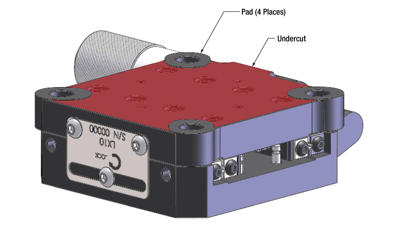
Click to Enlarge
Figure 174E Pads machined into Thorlabs' devices improve their stability when bolted in place. The pads are highly flat and project above the undercut region, which is highlighted red. The undercut limits the contact area with the table or breadboard.
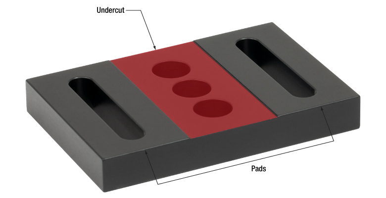
Click to Enlarge
Figure 174D This view of the bottom shows the undercut highlighted in red. By removing this material, the pads can be made maximally flat.
Click to Enlarge
Figure 174C For optimal stability, the base should be mounted with the undercut facing the optical table or breadboard.
Date of Last Edit: Dec. 9, 2019
| Posted Comments: | |
| No Comments Posted |