 Products Home / Optomechanical Components / Optical Post Assemblies / Mini-Series Optical Post Assemblies / Mini-Series Kinematic Base
Mini-Series Kinematic Base
- Kinematic Bases with Magnetic Retention
- Precision Ball and V-Groove Design for High Repeatability
- Top and Bottom Plates Available Individually or as a Complete Unit
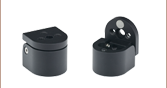
MKB19
Magnetic Base, 0.75" x 0.75"
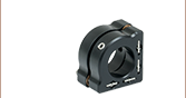
MKBT19
Top Plate of the MKB19 Base
MKBB19
Bottom Plate of the MKB19 Base
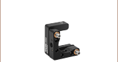
Application Idea
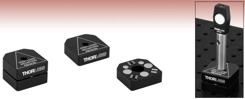
This application shows a BB03-E02 Mirror mounted in a MFM7 Mount on a 1" Mini-Series Post. The assembly is secured on a MKB19 Magnetic Base on a MBY6 Breadboard.


Please Wait
Click to Enlarge
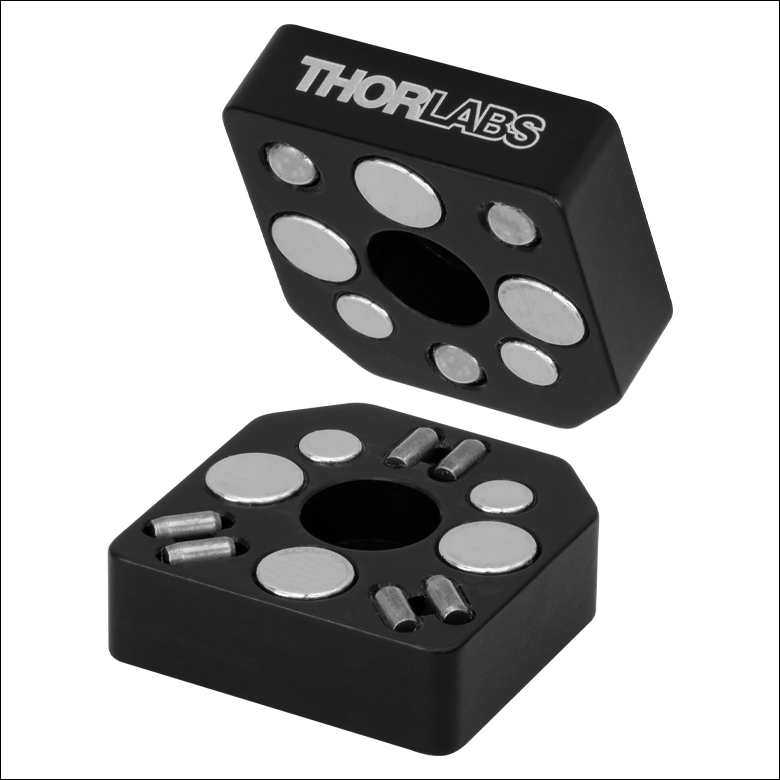
Figure 1.1 MKB19
Kinematic Base with its Five Pairs of Magnets and #4 (M3) Counterbores
Features
- 0.75" x 0.75" x 0.50" (19.1 mm x 19.1 mm x 12.7 mm) Kinematic Base
- Ball and V-Groove Design Allows High-Precision Positioning
- Top Plate Included in Complete Base (Item # MKBT19) Features an #4 (M3) Counterbore
- Bottom Plate Included in Complete Base (Item # MKBB19) has a #4 (M3) Counterbore
Thorlabs' Mini-Series Kinematic Base is an excellent method for mounting mini-series optomechanical components that need to be inserted and removed from the optical path with a high degree of repeatability. With a ball and V-groove design, the top plate can be inserted and removed with high repeatability. The top mounting plate and bottom base plate of the MKB19 kinematic base are magnetically coupled using five pairs of high-strength magnets which provide a holding force of 1.9 lbs. Additionally, both plates have a center-located #4 (M3) counterbored hole which allows either plate to be mounted to mini-series optomechanical components like optical posts. The top plate and bottom plate are available individually (as Item #s MKBT19 and MKBB19, respectively) for applications where multiple interchangeable parts may be desired. The MKBT19 top plate is engraved to specify the high load mounting region. This illustrates the area where the center of gravity should be located for maximum stability.
Three MKB19 bases were tested for angular repeatability of position. In each case, the top plate mirror assembly was removed and replaced 50 times. During this testing, we obtained a mean angular deviation of 4.16 µrad and a maximum of 11.9 µrad (see the Repeatability tab for more information).
Mini-Series Angular Repeatability Testing
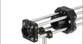
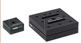
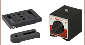
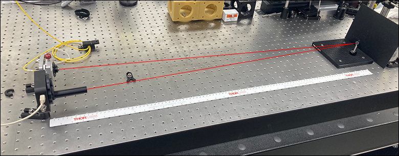
The procedure shown below illustrates the method used for determining the angular repeatability of the Mini-Series Kinematic Base. First, the bottom plate of the MKB19 kinematic base was fastened to the optical table. A Ø1/2" mirror (Item # PF05-03-P01) in a mirror mount (Item # MFM05) was attached to a 1" post (Item # MS1R), which was itself attached to the top plate of the MKB19. To ensure that only the movements of the MKB19 base were observed, the mirror, mirror mount, post and top plate were fixed together with epoxy. The top plate was then placed on top of the bottom plate. A fiber-coupler laser source (Item #s P1-630A-FC-2 and S1FC635) was collimated (Item # F110FC-633) and directed at the fixed mirror on top of the MKB19 base. The reflected beam was captured on a previous-generation BC106N-VIS beam profiler mounted 1 m away from the mirror.

Click to Enlarge
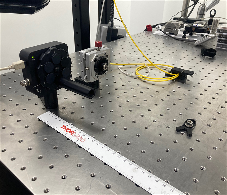
Figure 2.3 A PF05-03-P01 mirror is mounted in a MFM05 mirror mount on top of the MKB19
mini-series base.
Click to Enlarge
Figure 2.2 The S1FC635 source emits a 635 nm beam that is then collimated via a F110FC-633 collimation package. The reflected beam is captured on a BC106N-VIS beam profiler.
Click to Enlarge
Figure 2.1 Experimental Apparatus for Repeatability
Testing with 1 m Beam Path from the PF05-03-P01 Mirror to
the BC106N-VIS Beam Profiler
Three MKB19 bases were tested for angular repeatability of position. In each case, the top plate mirror assembly was removed and replaced 50 times. The position of the reflected beam was captured on the beam profiler for each placement of the top plate. The change in position of the beam on the beam profiler was used to extrapolate the angular deviation of the mirror on the kinematic base.
The results of the measurements are presented in Table 2.4 as the absolute difference in µrad between the original position of the beam on the sensor and the position after removing and replacing the top plate of the kinematic base. The combined value takes into account both X- and Y-position measurements and represents the net distance of the deviation from the origin.
| Table 2.4 MKB19 - Summary of Results | ||||
|---|---|---|---|---|
| Dimension | Mean | Maximum | Standard Deviation | Plot |
| |ΔX| | 3.73 µrad | 11.9 µrad | 4.64 µrad |  |
| |ΔY| | 1.39 µrad | 5.80 µrad | 1.92 µrad |  |
| Combined | 4.16 µrad | 11.9 µrad | 2.82 µrad |  |
| Posted Comments: | |
| No Comments Posted |